Note: Descriptions are shown in the official language in which they were submitted.
CA 02714172 2010-07-06
WO 2009/090264
PCT/EP2009/050564
1
RECYCLING CARBON FIBRE
This invention relates to the recycling of carbon fibres used in composite
materials. Carbon fibres are commonly used to make composite materials
comprising woven, chopped or milled carbon fibres in a resin matrix.
Such composites may be very light, strong and durable.
Carbon fibres comprise folded sheets of carbon layers. The carbon fibres
are typically unreactive and are fire and corrosion resistant. Each fibre
may be around 7 microns in diameter. Carbon fibre composites formed of
a resin and impregnated with continuous, chopped or milled carbon fibres
may have high tensile strengths and relatively low densities and hence
many applications are being developed for these materials.
Production of virgin carbon fibre is in the region of 30 000 tonnes per
annum and the demand for carbon fibre is significantly greater than
production, such that carbon fibres are not freely available.
Whilst demand for carbon fibres is high, it has been found that there is
significant wastage of material in production processes and it is estimated
that as much as 40% of virgin carbon fibre and resin is wasted in
manufacture of carbon fibre products. This material has traditionally been
sent to landfill.
Composite materials reaching the end of their life have also been sent to
landfill. These materials are, as described above, durable and generally
chemically inert. Consequently carbon fibre composite materials placed in
landfill can be expected to remain unchanged for a very long period of
time. With the present pressure on landfill space this is undesirable.
Furthermore, regulations restricting the use of landfill for composite
materials are being considered and implemented.
CA 02714172 2010-07-06
WO 2009/090264
PCT/EP2009/050564
2
In addition, the demand for carbon fibre is such that a means and method
of recycling carbon fibre and carbon fibre composites is desirable.
Some small scale attempts at recycling carbon fibres have been made but
they have been found to be complex and unsuited to larger scale
production. A number of existing methods employ inert atmospheres such
as nitrogen atmospheres and furthermore require extensive pre-treatment
including milling and/or chemical treatment of any material to be
recycled. It is known to carry out treatment of composite materials in
inert atmospheres. These known methods require the use of sealed units
so that the atmosphere can be purged and an inert gas introduced. Cost
and complexity is introduced in such sealed furnace methods.
Consequently the cost of recycling has been found to be high, the methods
are complex and have resulted in an end product of limited usefulness to
industry due to milling of the carbon fibre composite prior to recycling.
The resulting carbon fibre material has additionally been found to have a
proportion of char on or around the fibres and thus the end product is not
a clean product.
A simple cost effective method of recycling carbon fibre composite
materials has been sought for many years.
According to a first aspect of the invention there is provided a method of
recycling composite material comprising carbon fibres and a resin, the
method comprising:
providing a furnace comprising at least a heating portion;
providing a transporter for transporting the composite material through
the furnace;
loading the composite material on the transporter;
CA 02714172 2010-07-06
WO 2009/090264
PCT/EP2009/050564
3
removing resin in the heating portion of the furnace by means of chemical
decomposition at a first temperature, with the resultant generation of
fumes;
wherein the generated fumes are removed from the heating portion in a
controlled manner, such that the composition in the atmosphere in the
heating portion is controlled.
Specifically, according to a first aspect of the invention there is provided
a method of recycling composite material comprising carbon fibres and a
resin, the method comprising:
providing a furnace comprising at least a heating portion;
providing a transporter for transporting the composite material through
the furnace;
loading the composite material on the transporter and transporting the
composite material through the furnace;
detecting a percentage of oxygen in an atmosphere in the heating portion
when the composite material has entered this portion; and
removing resin from the composite material as it travels through the
heating portion of the furnace on the transporter, by means of chemical
decomposition at a first temperature, with the resultant generation of
fumes;
wherein the generated fumes are removed from the heating portion in a
controlled manner, such that the percentage of oxygen in the atmosphere
in the heating portion is controlled.
Preferably, the heating portion of the furnace has an atmosphere that
comprises air and the generated fume. The generated fumes (or fume) are
removed from the atmosphere in the heating portion in a controlled
manner such that the percentage of oxygen within the atmosphere of the
heating portion is sufficiently high so as to support decomposition and
CA 02714172 2010-07-06
WO 2009/090264
PCT/EP2009/050564
4
combustion of the resin but low enough to minimise or avoid combustion
of the carbon fibre.
Preferably chemical decomposition in the heating portion occurs at least
partially by means of a flame front on the surface of the composite
material. The flame front may be present across the width of the
composite material as it passes through the furnace on the transporter.
The furnace may have one or more temperature zones. It will be
understood that the temperature of the each zone may be varied. One or
more heating elements may be provided in the or each zone. One or more
heating elements in a primary heating zone may raise the composite
material to a first temperature at which decomposition and combustion of
the resin material can occur. Further heating elements may optionally be
present in subsequent heating zones to heat the composite material to a
desired temperature or to maintain the composite material at a desired
temperature.
The heating elements may be selected from electrical and gas heating
elements, but any elements for the provision of heat may be considered.
As the composite material reaches the first temperature decomposition
and combustion occurs. Fume is generated that rises into the atmosphere
of the furnace. The fume generated may reduce the percentage of oxygen
present in the atmosphere.
Preferably the fume reacts with oxygen present in the atmosphere to
combust further. This reaction is strongly exothermic. This exothermic
reaction may be used, alone or in combination with one or more heating
elements, to heat the composite material to a desired temperature or to
maintain the composite material at a desired temperature.
CA 02714172 2014-09-16
20157-286
=
It is further desirable to be able to measure the ratio of oxygen to fume in
the atmosphere and to maintain this ratio in a range supporting
decomposition of the resin and combustion of at least some of the
5 generated fume. It is desirable to maintain the ratio of oxygen to fume
so
as to ensure that there is sufficient oxygen to allow combustion of the
products of decomposition of the fume and to allow combustion of char
from the carbon fibre. It is particularly desirable to monitor and control
the o- xygen/fume ratio in the first and second heating zones.
A flame front may be generated on the surface of the composite material
after the composite material reaches the first temperature.
Advantageously the size of the flame front can be controlled by
controlling the percentage of oxygen in the atmosphere. In particular, the
dimension of the flame front in the direction of travel of the composite
material or width of the flame front may be controlled to be 20cm or less,
and more preferably to be 10cm or less, such as from 1 to 9cm, e.g. from
2 to 8cm, for example from 3 to 7cm, by controlling the percentage of
oxygen in the atmosphere.
It is a known issue with earlier methods that the presence of any oxygen
within a furnace can lead to combustion and potentially to the risk of an
explosion. Accordingly there has, to date, been a mindset to ensure that
the atmosphere is purged and that an inert atmosphere is used, such that
combustion of the resin does not occur in the furnace.
In contrast, some embodiments of the present invention detect and control the
oxygen in the atmosphere in the heating portion of the furnace. As discussed
in
more detail below, a combination of the generated fumes and air may suitably
be
used in the atmosphere in the heating portion of the furnace to ensure
CA 02714172 2010-07-06
WO 2009/090264
PCT/EP2009/050564
6
that sufficient oxygen is present, e.g. from 1 % (v/v) and up to 16%
(v/v), such as from 1% (v/v) and up to 10% (v/v).
It is preferred that the transporter transports the composite material
through the furnace in a substantially linear fashion. As discussed below
in more detail, it is advantageous to move the composite material in a
linear fashion rather than for the material to be passed around bends, or
tumbled or rotated or crushed.
According to a second aspect of the invention there is provided a furnace
for recycling composite carbon fibre material comprising carbon fibre and
a resin component, the furnace comprising a heating portion for heating
the material to a first temperature so as to remove resin by means of
chemical decomposition with the resultant generation of fumes, and a
transporter for transporting the composite material through the heating
portion, wherein the heating portion comprises an oxygen detection means
and a controller for controlling a percentage of oxygen in the atmosphere
in the heating portion by controlling the removal of generated fumes from
the heating portion.
Preferably the controller controls a rate of extraction of fume in response
to the percentage of oxygen in the atmosphere of the heating portion of
the furnace.
Preferably the furnace further comprises a loading portion. An entrance is
provided between the loading portion and the heating portion. The
entrance is preferably of restricted dimensions relative to dimensions of
the heating portion. The entrance may be at least partially sealable so
providing a variable opening. It may be desirable to be able to vary the
open dimensions of the entrance to control ingress of air to the heating
portion.
CA 02714172 2010-07-06
WO 2009/090264
PCT/EP2009/050564
7
Preferably the furnace further comprises a cooling portion. The cooling
portion may also have restricted dimensions relative to the heating
portion. Air preferably may ingress the heating portion from the cooling
portion.
In a preferred embodiment it is not necessary to provide fans, blowers,
pumps or other positive air directing apparatus to move air into the
heating portion. Preferably removal of the fume creates a natural draw. In
a particularly preferred embodiment fume is removed from the heating
portion to an abatement unit and draw from the abatement unit is
sufficient to draw air into the heating portion.
Suitably the removal of the fume is via vents or other apertures. Natural
convection assists movement of the fume to and through the vents. The
size of the vents may be controlled to control the removal of the fumes
from the furnace atmosphere. The length of time that the vents are open
may be controlled to control the removal of the fumes from the furnace
atmosphere. More detail regarding the vents is provided below.
In one embodiment, the heating portion of the furnace has an atmosphere
that consists essentially of, or consists entirely of, air and the generated
fumes. However, in an alternative embodiment, additional gases may be
present in the atmosphere. For example, inert gases such as nitrogen or
argon may be present in the atmosphere. Preferably such additional gases
are present at a level of 10% (v/v) or less, such as 5% (v/v) or less, e.g.
2% (v/v) or less. In one embodiment, gases other than air and generated
fumes are present at a level of from 0 to 10% (v/v), such as from 0 to 5%
(v/v), e.g. from 0 to 2% (v/v).
CA 02714172 2014-09-16
20157-286
8
The heating portion or first portion of the furnace may comprise a stepped
heating tunnel. This portion may be arranged in alternative constructions.
The form of this portion may not be a stepped form but alternative
arrangements in which the atmosphere can be adequately controlled over
the transporter may be utilised. In a preferred embodiment this portion
has a constant height.
The first temperature, at which the resin is removed by means of
chemical decomposition, may suitably be from 200 C to 600 C and
preferably from 300 C to 500 C, such as from 400 C to 500 C. A most
preferied range is from 425 C to 475 C or the temperature may be
maintained at 500 C.
At this temperature resin components of the composite material break
down and are burnt off the carbon fibres in a gaseous fume. The gaseous
fume product of this decomposition contains relatively little oxygen.
Typical levels of oxygen in the fumes are from 1% to 5% v/v.
In one embodiment the first or heating portion of the furnace is arranged
such that the fume is initially retained in this first portion, reducing the
proportion of oxygen present in the atmosphere of this first heating
portion and preventing or reducing the possibility of oxidation of the
carbon fibres and supporting decomposition of the resin component rather
than combustion thereof.
It is ultimately desirable to flush fume from the first heating portion but it
is also desirable to maintain enough fume within the first heating portion to
minimise oxidation of the carbon fibre. Accordingly, the controlled removal
of the fume is important to some embodiments of the invention.
CA 02714172 2010-07-06
WO 2009/090264
PCT/EP2009/050564
9
Most preferably, fume removal/extraction is controlled by the use of a
pressure of from -5 to +5 mbar, preferably from -2 to + 2mbar and more
preferably from -2 to -1 mbar. In a preferred embodiment the pressure is
-lmbar.
In one embodiment, breakdown of the resin components is by means of
pyrolysis of these components. In true pyrolysis no oxygen is present. In
particular, in true pyrolysis the chemical decomposition is substantially
by heat. Accordingly, substantially no reactions occur by the presence of
other components; e.g. a catalyst or oxygen.
Accordingly, in one embodiment, the decomposition in the first heating
portion of the furnace is carried out in the presence of substantially no
oxygen.
However, in a preferred embodiment the decomposition is in the presence
of low amounts of oxygen in the atmosphere of the heating portion.
In such embodiments, less than stoichiometric amounts of oxygen are
present, so as to achieve chemical decomposition. In other words, the
amount of oxygen present in the atmosphere of the first heating portion of
the furnace is less than 100% of the amount required for combustion. For
example, the amount of oxygen present in the atmosphere of the first
heating portion of the furnace may be 90% or less of the amount required
for combustion, such as 80% or less, 70% or less, or 60% or less.
In one embodiment, the oxygen is present in an amount of 50% of
stoichiometric or less, such as 40% of stoichiometric or less, e.g. 25% of
stoichiometric or less, such as 10% of stoichiometric or less.
CA 02714172 2014-09-16
20157-286
Preferably the decomposition of the resin in the first heating portion of
the furnace is carried out in the presence of oxygen in an amount of from
0.5 to 90% of stoichiometric, such as from 1 to 80% of stoichiometric,
for example from 1.5 to 50% of stoichiometric, such as from 2 to 40% of
5 stoichiometric, e.g. from 5 to 25% of stoichiometric.
In manufacture of carbon fibre, as in recycling, it is also desired to
prevent oxidation of carbon fibres and this has conventionally been
achieved by the use of an inert atmosphere over the carbon fibres.
10 Typically the inert atmosphere may be nitrogen although other inert
gases
may be used. The use of nitrogen adds complexity and cost to the
process. Some small scale laboratory attempts to recycle carbon fibre
have been made and these have all used nitrogen as an inert atmosphere to
=
prevent oxidation of the carbon fibre and to enable decomposition of the
resin component to occur.
By contrast, some embodiments of the instant invention utilise an open
furnace and control a flow of fume out of the furnace and hence the
percentage of oxygen in the atmosphere to reduce oxidation of the carbon.
This is simpler and easier to control.
In some embodiments of the instant invention the proportion of oxygen in the
atmosphere in the first portion of the furnace preferably is controlled to
less than
16% (v/v), e.g. from 1 % (v/v) and up to 16% (v/v). For example, it may be
controlled to less than 10% (v/v), e.g. from 1% (v/v) and up to 10%
(v/v). In one embodiment the proportion of oxygen in the atmosphere in
the first portion of the furnace is controlled to less than 5% (v/v), e.g.
from 1% (v/v) and up to 5% (v/v). In a most preferred embodiment the
percentage of oxygen is less than 5% (v/v) but greater than 1% (v/v).
CA 02714172 2014-09-16
20157-286
11
In one embodiment the proportion of oxygen in the atmosphere in the first
portion of the furnace may be controlled so as to be from 2 and up to
16% (v/v), e.g. from 2% to 10% (v/v), such as from 2 to 5% (v/v).
In one embodiment the proportion of oxygen in the atmosphere in the first
portion of the furnace may be controlled so as to be from 3 and up to
16% (v/v), e.g. from 3% to 10% (v/v), such as from 3 to 5% (v/v).
The exactproportion of oxygen selected will depend on local conditions
, 10 and the material being processed, as would be appreciated by the skilled
man.
In one embodiment, the proportion of oxygen in the atmosphere in the
first portion of the furnace is controlled to be substantially constant
throughout the furnace atmosphere, as the composite material passes
through the furnace. For example, the proportion of oxygen may be
controlled so that it varies by 3% (v/v) or less as the composite material
passes through the furnace, such as by 2% (v/v) or less, preferably by 1%
(v/v) or less, e.g. by 0.5% (v/v) or less.
It will be understood that when the furnace is first started up
decomposition of the resin component may not occur as there will not be
enough fume to control the atmosphere and provide a suitably oxygen
poor environment. However, it will be understood that in a preferred
embodiment the resin decomposes very rapidly and produces large
quantities of decomposed gases or fume which provide a reducing
atmosphere. This may be achieved within a few seconds of a first load of
carbon fibre material entering the first heating portion.
Recycled carbon fibre reclaimed using the method of some embodiments of the
invention has been found to have desirable properties. For example the
recycled carbon
CA 02714172 2010-07-06
WO 2009/090264
PCT/EP2009/050564
12
fibre has been found to have improved adhesion properties compared to
virgin carbon fibre. It has also been found that the electrical properties
are changed in the recycling process and the conductivity may be
significantly enhanced.
Preferably the fume removed from the first heating portion is directed to
external burners located adjacent to the first portion. The external burners
may operate at a much higher temperature than the first portion.
Typically a temperature of 1000 to 1500 C may be used, such as 1100 to
1300 C, for example in the region of 1200 C. The fume may therefore be
further burnt by the external burners.
Preferably waste gases released after the fume has been burnt by the
external burners are clear. Further treatment of waste gases may be
incorporated in order to reduce any ecological impact of the method of
recycling carbon fibres. The fume may also be condensed in order to
obtain a low grade fuel oil. Alternatively the fume may be cracked back
to the original polymers present in the fume. These polymers may be used
in other applications such as in adhesives. Condensation or cracking of
the fume may be carried out by conventional means and methods.
In a preferred embodiment the fume is treated in an abatement unit and
waste gases released into the atmosphere by means of chimneys. These
may be part of the abatement unit or may be separate from the abatement
unit. It is also desirable to integrate the abatement unit with the furnace to
facilitate energy transfer between the furnace and the abatement unit and
so reduce an overall power required to be supplied to the furnace.
Preferably the transporter comprises a linear transporter. In particular,
the transporter is suitably substantially linear along its length that passes
CA 02714172 2014-09-16
20157-286
13
through the furnace. In a preferred embodiment, the transporter is
substantially linear along its entire length.
A linear transporter is particularly well adapted to transport the composite
material such that the material is not rotated or crushed in transit through
the furnace. It may be desirable to ensure that the composite material is
not damaged or crushed in transit through the furnace. It is known that an
important quality of carbon fibre is known as "cosmetic quality" and the
use of a linear transporter provides a product with improved aesthetics.
Additionally, if the carbon fibre is damaged then the resulting surface
defects can be detrimental to the tensile strength of the carbon fibre. An
advantage of using a linear transporter is that the composite material may
be placed on the transporter and then moved through the furnace by the
transporter with linear movement. The composite material is not rotated
or crushed in movement through the furnace nor is it tumbled.
Accordingly, the recycled composite material contains clean and
undamaged carbon fibres after passing through the furnace.
A further advantage of some embodiments of this invention relates to the
recycling
of composite materials that are formed of laminar sheets. These may be sheets
of
carbon fibres only, or may also contain sheets of additional material such
as sheets of reinforcing glass fibres or metal fibre. Due to the fact that
the entire piece of composite material can be transported through the
furnace without being pre-chopped into small pieces, and can travel
without turbulence or tumbling through the furnace, the composite
material cleanly delaminates into sheet layers in the heating portion of the
furnace. This means that the or each sheet of additional material may be
removed by lifting, sliding or pulling the sheet out from the delaminated
composite material. Accordingly, metal and other materials may be easily
extracted from the composite material after the material exits from the
furnace.
CA 02714172 2010-07-06
WO 2009/090264
PCT/EP2009/050564
14
In a preferred embodiment the composite material is loaded onto a
transporter comprising a continuous feed mechanism to be transported
through the heating tunnel. Preferably the continuous feed is a continuous
belt and the belt may be made of steel or other heat resistant, durable
material.
The belt travels through the first portion. A period of time, or dwell time,
spent in the first portion may be varied by controlling a rate of movement
of the belt. A control mechanism may be provided to control the rate of
movement of the belt. A predetermined rate of movement may be
selected. The rate of movement may be selected according to the
temperature of the first portion and/or the material to be recycled.
Preferably the rate of travel of the belt is controlled by means of the
controller. It may be desirable to be able to vary the speed of movement
of the belt during the recycling process. Such a variation may be in
response to output signals from the oxygen meters and/or from
temperature sensors. Examples of speeds that may be used for the belt
are 2m/min or higher, e.g. from 2 to 8m/min, such as 3m/min or higher,
e.g. from 3 to 6m/min. A speed of about 4 m/min may be used in one
embodiment.
The belt may be arranged to transport small quantities of material. It may
also be suitable for transporting larger items such as golf club shafts or
rolls of woven carbon fibre. Other larger items may include such items as
bicycles, racing car panels including Fl car panels, and even sections of
an aircraft wing.
It is preferred that composite materials to be recycled are less than 2 m
wide and less than 0.25 m high. A more preferred range is that the
materials are less than 1.5m wide and less than 0.2m high. However,
CA 02714172 2014-09-16
20157-286
these preferred maximum sizes result from dimensions of a throat
entering the preferred heating tunnel and alternative first heating portions
of greater size and able to deal with larger articles of material to be
recycled can be readily envisaged. The skilled man will appreciate that
5 the height and width of an article will depend upon its orientation and
that
an article that in one orientation does not fit these dimensions may be able
to be rotated to another orientation so as to fit these dimensions. These
preferred sizes result from the dimensions of the preferred heating tunnel
and ihe skilled man will understand that the dimensions may be varied. It
10 is envisaged that it an alternative heating tunnel could be fabricated with
alternative dimensions in which the height is closer to the width.
However, it has been found that control of the dimensions of the throat
are important. In a preferred embodiment it has been found that the
narrower the throat the easier it is to control a heating profile within the
15 heating portion. Alternatively the throat or opening may be adjustable to
allow a larger article to enter the heating portion and the throat may then
be partially or wholly closed.
A thickness of composite materials to be recycled may be varied. The
thickness of the composite material may affect the ideal dwell time spent
in the furnace. In general the thicker an item is the greater the dwell
time.
It will be understood that there is no limit on the length of an article to be
recycled since the process is continuous. However, it is preferable to cut
the articles into manageable lengths in order to facilitate handling of the
material to be recycled. A typical length may be in the region of 2m.
It is a particular advantage of the method of some embodiments that little or
no pre-
treatment is required. The material to be recycled does not have to be
chemically
treated, or reduced to small sizes by shredding, chopping or milling. This
CA 02714172 2010-07-06
WO 2009/090264
PCT/EP2009/050564
16
is in part because the dimensions of the throat allow larger items to pass
into the furnace.
In one embodiment, the composite materials to be recycled are only
chopped or otherwise pre-treated to reduce their size if they are lm wide
or more and/or 0.1m high or more. In a preferred embodiment, the
composite materials to be recycled are only chopped or otherwise pre-
treated to reduce their size if they are 1.5m wide or more and/or 0.2m
high or more. In one embodiment, the composite materials to be recycled
are only chopped or otherwise pre-treated to reduce their size if they are
2 m wide or more and/or 0.25 m high or more.
Preferably the method is operated continuously and material can be
continuously loaded onto the belt and passed into the first heating portion.
An advantage of this is that it is not necessary to store material
preparatory to processing a batch of material. Continuous operation of the
first heating portion is also advantageous. In particular, continuous
operation of the first heating portion allows the composite material to be
fed into the furnace at a desired rate, dependent on the materials
available. Maintenance of a continuous temperature is more energy
efficient. Furthermore cycling of heat in the furnace is both inefficient
and may be detrimental to the fabric of the furnace leading to a reduced
life cycle. It will be understood that the batch processing of material is
possible although not preferred. It has been found to be commercially
undesirable at the present moment.
A second heating portion of the furnace may be provided which may
preferably operate at a higher temperature than the first heating portion of
the furnace.
CA 02714172 2014-09-16
20157-286
17
In a preferred embodiment of the method, after resin has been removed in
the first heating portion of the furnace the remaining material is heated in
a second heating portion of the furnace which operates at a higher
temperature than the first portion of the furnace.
Preferably the second heating portion of the furnace heats the material
from 500 C to 900 C and more preferably from 550 C to 800 C. Most
preferably the temperature in the second portion is from 500 C to 700 C,
preferably from 550 C to 600 C or more preferably from 600 C to 700 C.
' 10 In one example of the method the temperature of the= second heating
portion is from 600 C to 650 C, such as about 620 C.
It is desirable that the second portion of the furnace operates at a higher
temperature than the first portion of the furnace. It is also preferred that
the temperature of the second portion is not too high as will be further
discussed below.
A minimal amount of further fume may be generated in the second
portion. Any further fume may be channelled to the external burners or
abatement unit and be burnt off or otherwise treated.
As the second heating portion preferably operates at a higher temperature
than the first portion it has been found that the second portion burns off
any char formed on fibre in the material.
Char arises from retarded decomposition of resins in the composite
material. Decomposition is retarded due to an insufficient supply of
oxygen. Use of an inert atmosphere excludes oxygen and therefore char is
a significant problem for existing methods which use an inert atmosphere.
In the instant method of some embodiments, however, oxygen is not excluded and
so decomposition of the resin component occurs followed by combustion of
CA 02714172 2010-07-06
WO 2009/090264
PCT/EP2009/050564
18
the char with the oxygen present to form carbon dioxide and carbon
monoxide so reducing the quantity of char remaining on the carbon fibres.
A higher quality product is thus obtained.
The presence of char on or amongst carbon fibres may be undesirable
since it is both an impurity and may affect the physical characteristics of
the carbon fibres. Char may be seen on the surface of carbon fibres when
viewed using a scanning electron microscope (SEM).
It has however been discovered that the presence of char may be desirable
for certain applications of the recycled carbon fibre material, where the
recycled material is to be used in an application where activated carbon is
involved, for example water purification or catalytic beds.
Accordingly, it is desirable to control the removal of char from the
carbon fibres so that a clean product is produced if this is desired, but
equally such that a product comprising char is produced if desired.
According to a third aspect of the invention there is provided a method of
recycling composite material comprising carbon fibres and a resin, the
method comprising:
providing a furnace comprising at least a first heating portion and a
second heating portion;
providing a transporter for transporting the composite material
through the first heating portion;
loading the composite material on the transporter and transporting
the composite material through the furnace;
detecting a percentage of oxygen in an atmosphere in the first
heating portion when the composite material has entered this portion; and
removing resin in the first heating portion as it travels through this
portion of the furnace on the transporter, by means of chemical
CA 02714172 2010-07-06
WO 2009/090264
PCT/EP2009/050564
19
decomposition at a first temperature, with the resultant generation of
fumes;
removing the fumes from the first heating portion in a controlled manner,
such that the percentage of oxygen in the atmosphere in the first heating
portion is controlled
transporting the material to be recycled through the second heating
portion on the transporter, after being transported through the first
heating portion;
wherein the second heating portion is operated at a second temperature
and the second temperature is selected to control removal of char from
carbon fibres.
The second portion of the furnace operates primarily to remove char
deposited on the carbon fibres in the first portion of the furnace. The
amount of char deposited in the first portion is less that the amount of
char deposited in processes carried out under inert atmospheres but it may
still be desirable to remove as much of the char as possible. It has been
found that the most preferred temperature range of from 550 C to 600 C
is high enough to remove any char deposited on the carbon fibres without
baking the char onto the carbon fibres. However a temperature in the
range of from 600 C to 650 C may be more desirable in some
embodiments. If the temperature is too high the carbon fibres can oxidise
in the presence of heat and oxygen and this is not desired.
It is important to control the dwell time of the carbon fibre material in the
second portion of the furnace since if the dwell time is too long the fibres
reach a higher temperature and oxidise whilst if the dwell time is too
short char is left on the fibres. Preferably the dwell time is in the region
of 5 minutes. The thickness of the material may affect the desired dwell
time in the second portion and a thicker item may require a longer dwell
time. In general it has been found that a suitable dwell time is from lmin
CA 02714172 2010-07-06
WO 2009/090264
PCT/EP2009/050564
to 10min, such as from 2min to 8min, preferably from 3min to 7min, with
a most preferred dwell time being from 4min to 6min. If the dwell time is
too great then the carbon fibres will oxidise.
5 It will be appreciated that if some or all of the char is to be retained
on
the fibres the temperature of the second heating portion may be reduced
or the dwell time may be shortened. It is desirable that the controller can
control the variable of dwell time and temperature in order to control an
amount of char on the carbon fibres after recycling of the composite
10 material has been completed. Alternatively or in addition the oxygen
content in the atmosphere may be controlled such that incomplete
combustion of the resin or resin decomposition products occurs and a
greater proportion of char is deposited on the carbon fibres.
15 Preferably the atmosphere in the second heating portion is substantially
clear and the ratio of oxygen in the atmosphere is substantially the same
as that of atmosphere. It may not be necessary to control the atmosphere
in the second heating portion of the furnace. The carbon fibre may be
seen to burn with a small blue flame near the surface of the carbon fibres
20 as the char is burnt off the fibres.
The process of removal of char may be termed "polishing" or upgrading
and results in fibres having a smoother surface with less adhered matter.
Preferably the method includes a step, after the heating step or steps,
wherein the recycled material is cooled, for example by the use of water.
This step may be carried out in a third cooling portion of the furnace. In
a preferred embodiment the third cooling portion is water cooled. The
material may be cooled over a period of around 15 minutes before being
collected in receptacles. Typically the water cooled section is carried out
CA 02714172 2010-07-06
WO 2009/090264
PCT/EP2009/050564
21
using a jacketed cooling section. The cooling process is completely
conventional.
Preferably receptacles are arranged to receive a continuous output of
recycled material from the third cooling portion.
Preferably the receptacles are used to move the recycled material to a mill
where the material may be chopped or milled in a conventional manner.
A first and/or a second buffer heating zone may be provided. The first
buffer zone may be provided before the first heating portion. The first
buffer zone may operate at a temperature of around 200 to 400 C. In one
embodiment it may be from 200 to 300 C. In another embodiment it may
be around 400 C. The exact temperature at which the first buffer zone
operates may be varied but is preferably below the temperature of the
first heating zone. The temperature is preferably low enough that gassing
off of the resin component does not occur in the buffer zone but the
material is pre- warmed before entering the first heating portion and the
heat in the first heating portion is retained.
In a preferred embodiment the second buffer zone is also maintained at a
temperature of around 200 to 400 C. In one embodiment it may be from
200 to 300 C. In another embodiment it may be around 400 C. In a
preferred embodiment the second buffer zone is located between the
second heating portion and the third portion of the furnace in which
cooling of the material occurs. Again, the buffer zone ids operated so as
to retain heat within the first and second heating zones and to increase the
overall efficiency of the furnace.
In a preferred embodiment the belt operates continuously through the
furnace and moves at a substantially constant speed. It can be foreseen,
CA 02714172 2010-07-06
WO 2009/090264
PCT/EP2009/050564
22
however, that more than one belt could be used and material may be
transferred from one belt to another. If separate belts are used then each
belt may run at a different speed in each of the portions so that a dwell
time in each portion may be individually varied and controlled.
Recycled material may be milled to from 50 to 500 microns and
preferably from 100 to 400 microns and most preferably from 200 to 300
microns or may be chopped to lengths from 1 to 250mm or preferably
from 2 to 200mm and most preferably from 3 to 150 mm. Alternative
lengths may be selected above or below this range. Alternative lengths
may be selected depending on the use to which the carbon fibres are to be
put. The precise lengths selected may vary depending on the chopping
equipment.
Alternatively, recycled material may be reused without chopping or
milling. The separation of laminated composite material that delaminates
in the heating portion has already been referred to above. At present it is
envisaged that separation of delaminated material will be carried out
manually but it will be appreciated that it may be automated.
Reuse without chopping or milling is particularly suited to recycling
material such as woven pre-preg rolls. These materials may require
recycling because the resin is no longer "in-date" but by using the
described method the rolls may be returned for re-use with a fresh resin
without compromising the woven structure of the carbon fibre material.
According to a fourth aspect of the invention there is provided a method
of recycling composite carbon fibre material comprising carbon fibre and
a resin component, the method comprising heating the composite material
in an open furnace such that that the resin component undergoes thermal
decomposition with resultant generation of fumes, whilst providing an
CA 02714172 2010-07-06
WO 2009/090264
PCT/EP2009/050564
23
atmosphere in the furnace wherein a percentage of oxygen in the
atmosphere is controlled through control of the removal of the generated
fumes such that thermal decomposition is substantially complete but
oxidation of the carbon fibres is reduced or prevented.
Preferably a controller is provided that controls removal of fume from the
furnace the controller being connected to a sensor adapted to sense the
level of oxygen in the atmosphere.
Preferably the sensor comprises means of monitoring the proportion of
oxygen in the atmosphere within a pre-determined range. The sensors
may be arranged to sample and measure the percentage of oxygen in the
atmosphere at predetermined intervals. For example the percentage of
oxygen may be sampled and measured every 30 seconds or every minute.
Alternatively the sensors may sample the percentage of oxygen in the
atmosphere continuously.
It may be desirable to set each sensor independently. Thus one or more
sensor may sample the atmosphere continuously while one or more sensor
may be set to sample the atmosphere at regular intervals, e.g. every 10
seconds or every 30 seconds. Equally, a number of sensors may be set to
sample the atmosphere at regular intervals, with each sensor being
independently set in terms of the interval, e.g. one sensor may be set to
sample the atmosphere every 10 seconds whilst another is set to sample
every 30 seconds or every minute.
The period of sampling may vary with the location of the sensor. It may
be desirable to sample the atmosphere in the first heating portion
continuously while sensors in the second heating zone sample
periodically, for example every 5, 10, 20 or 30 seconds. Sensors in the
CA 02714172 2010-07-06
WO 2009/090264
PCT/EP2009/050564
24
buffer zones may sample periodically but at a longer period between
samples, for example every 20, 30 or 60 seconds.
Preferably the controller controls a rate of extraction of the fumes in
response to the percentage of oxygen in the atmosphere of the heating
portion.
Preferably the proportion of oxygen in the atmosphere is maintained
within a pre-determined range by increasing or decreasing an exit flow of
the generated fume out of the first heating portion as required.
One or more vents may be provided. The or each vent may be
electrically controlled to open to a preselected degree. The degree of
opening may be between 0% and 100% in response to an output from the
controller. Preferably more than one vent is provided in the first heating
section. Advantageously one or more vents may be provided in each of
the heating zones. It is preferred that each vent has a manual control
mechanism. The vents may be opened and closed in response to output
signals from the controller. The controller may select a degree of opening
and a period for opening for the or each vent. The period of opening may
be varied in response to atmospheric oxygen content measurement signals
from the or each oxygen meter. In a furnace having more than one vent,
each vent may operate independently of the other vents in response to
signals from the controller.
A temperature sensor may also be provided to monitor the temperature
reached in the heating tunnel. The temperature may be varied in
proportion to a rate of travel of the transporter. Preferably a dwell time
of composite material in the heating tunnel is from 3 to 15 minutes and is
preferably from 5 to 12 minutes. Particularly preferred dwell times are 6
minutes and 12 minutes.
CA 02714172 2014-09-16
20157-286
In one embodiment, the dwell time is 12 minutes or less, such as 10
minutes or less, e.g. from 1 to 10 minutes, such as 5 to 10 minutes.
5 The dwell time may be reduced if the temperature is increased.
Alternatively if the temperature is lower the dwell time may be increased
to ensure that a resin component of the composite material is burnt off.
The dwell time is significantly shorter than the dwell time of known
processes.
In a true pyrolytic system oxidation of the carbon cannot occur but in the
instant invention a proportion of oxygen is present in the atmosphere of
the first portion of the furnace and therefore some oxidation of the carbon
fibres will occur. Thus in controlling the decomposition of the resin
component both the temperature and the dwell time at the temperature
must be considered. As the temperature increase the dwell time can be
reduced in order to reduce the unwanted oxidation of carbon fibres.
In some embodiments of the present invention, due to the fact that the fumes
are
combusted, creating heat due to the exothermic reaction, the dwell time can be
reduced to times significantly less than would have been predicted, e.g.
15 minutes or less, such as 12 minutes or less. By having a faster rate of
travel/lower dwell time, the risk of exothermic runaway/explosion is
reduced as well as the oxidation of the carbon fibres being substantially
avoided.
High speeds/low dwell times are in particular made possible by the use of
a linear transporter. If high speeds were used with a non linear
transporter the risk of damage to the fibres would be increased
significantly.
CA 02714172 2010-07-06
WO 2009/090264
PCT/EP2009/050564
26
Although in a preferred embodiment the flow of gases is caused only by
creating a natural draw, in an alternative embodiment a fluid mover for
controlling the flow of gases through the tunnel may be provided as at
least part of the controller for controlling the atmosphere in the first
heating portion. This may comprise one or more fans or pumps. A motor
driven gate valve may be provided together with means of drawing the
fume from the first heating portion. The flow rate of gases passing
through the gate valve may be controlled as previously described.
As described above an oxygen meter may also be provided to measure the
percentage of oxygen in the atmosphere. Preferably the oxygen meter is
located adjacent to the entry to the second zone, being the first heating
zone. This is a point at which combustion is occurring and fume is
evolved. The rate of fume withdrawal may be varied depending on the
resin volume fraction of the composite being processed. The resin volume
fraction is part of the MSDS which will be supplied with the material.
The extraction will be monitored by the oxygen meter and the extract fan
is controlled depending on oxygen levels.
In another embodiment an oxygen meter may be provided to measure the
percentage of oxygen in the atmosphere which is located towards the
middle of the second zone.
It may be that more than one oxygen meter is provided to measure the
percentage of oxygen in the atmosphere, for example there may be two,
three, four or more meters.
In one embodiment, there are four meters, one in each zone.
It is desirable that certain parameters such as temperature of the furnace
and dwell time of the material in each portion of the furnace be pre
CA 02714172 2010-07-06
WO 2009/090264
PCT/EP2009/050564
27
selected before the composite material is loaded onto the transporter. This
can be done if the MSDS is supplied with the material. It will be
understood that this information may not always be available in which
case a "best guess" of the appropriate parameters can be made.
Measurement of oxygen content and temperature is carried out
periodically and the percentage of oxygen in the atmosphere is controlled
to maintain the oxygen content at or below 16% (v/v) by opening and
closing of the vents.
It is desirable that a pressure differential be maintained between a first
end of the first heating portion and a second end of the first heating
portion adjacent to a second portion of the furnace. The pressure
differential may be in the region of -lmbar. However, this may be
adjusted to suit local conditions. The
controller for controlling the
atmosphere in the first heating portion may control this pressure
differential.
It is desirable that the first heating portion be arranged such that fume
from the resin component is held in the first heating portion over the
carbon composite material.
In one preferred embodiment the first portion is provided with a sloping
roof. The roof slopes from the second portion downwards towards an
"off-take" located above the throat of the first heating portion. This
arrangement allows fumes from the first heating portion to be held
substantially within the first portion. Air moves from the third and second
portions towards the first heating portion directing fume that travels
forward into the second portion to return to the first heating portion.
Accordingly the second heating portion has a low level of fume and the
third portion has a substantially clean atmosphere.
CA 02714172 2010-07-06
WO 2009/090264
PCT/EP2009/050564
28
First, second, third and fourth portions of the furnace may refer to
designated zones of a furnace rather than separate areas of the furnace.
Alternatively the furnace may be arranged such that the first and second
heating portions are contiguous and buffer zones are maintained before
and after the heating portions.
Extraction of the fume is therefore carefully controlled. Since the fume
comprises gaseous material burnt off from the resin component, the
atmosphere containing the fume is relatively low in oxygen. Reaction of
carbon fibre with oxygen is therefore retarded. However it is not
desirable to reduce the oxygen content to substantially zero as then
decomposition and subsequent combustion of the resin content will not be
able to be completed and deposition of char will be increased.
Preferably the furnace includes a second heating portion which can be
heated to a second temperature that is greater than the temperature of the
first portion. The dwell time of the material in the second portion of the
furnace is in the region of from 3 to 5 minutes and in this portion
decomposition of any remaining resin component occurs and char
deposited on the carbon fibres is burnt off leaving the carbon fibres
relatively clean and free of char and sizing material.
According to a fifth aspect of the invention there is provided a method of
recycling composite carbon fibre material comprising carbon fibre and a
resin component, the method comprising heating the composite material
such that that the resin component undergoes thermal decomposition with
resultant generation of fumes, whilst providing an atmosphere wherein the
oxygen content is controlled through control of the removal of the
generated fumes such that thermal decomposition is substantially complete
but oxidation of the carbon fibres is reduced or prevented.
CA 02714172 2014-09-16
20157-286
29
Preferably the fume is held over the composite material for a period of
time reducing an amount of oxygen available to the carbon fibre from the
atmosphere.
According to a sixth aspect of the invention there is provided a method of
reducing a power required in a furnace to thermally decompose resin in a
composite material comprising carbon fibres and resin wherein in the
method composite material is heated in the furnace to a first temperature
at which fumes are generated and a percentage of oxygen in an
atmosphere in the furnace is controlled such that combustion of the fumes
occurs generating heat within the furnace.
It will be appreciated that as combustion of the fume is an exothermic
reaction it generates a considerable amount of energy in the form of heat.
This has been a safety issue in previous methods but in controlling the
amount of oxygen available in the atmosphere it is possible to control the
combustion reaction and so control the heat generated. Also, in some
embodiments of the present invention the system is not a sealed system,
which reduces the danger, whereas in prior art systems a sealed furnace
with an inert atmosphere was used.
In a preferred furnace heat is supplied by heating elements such as
electrical elements. Other heat sources can be used as the heating
elements. The amount of heat supplied by the electrical elements can be
reduced in response to the heat generated from the combustion reaction.
Preferably the controller is adapted to control the heat output of the
electrical elements and to do so in response to temperature sensor signals.
CA 02714172 2014-09-16
20157-286
According to a seventh aspect of the invention there is provided recycled
carbon fibre
resulting from a method according to a first, third, fourth, fifth or sixth
aspects of the
invention.
Preferably the recycled carbon fibre comprises articles formed of carbon
fibre.
5 In an alternative embodiment the recycled carbon fibre comprises chopped
carbon fibre
strands. The chopped carbon fibre strands may have an un-sized finish and a
proportion of
char of less than 1%.
Preferably the recycled carbon fibre has improved wet-out and interfacial
adhesion
characteristics in forming composite materials. The characteristics may be
improved over
10 those of virgin carbon fibre. Additionally composite materials
incorporating recycled carbon
fibre may be found to have improved Young's modulus and tensile strength.
According to another aspect of the present invention, there is provided a
method of recycling
composite material comprising carbon fibres and a resin, the method
comprising: providing a
furnace comprising at least a heating portion; providing a transporter for
transporting the
15 composite material through the furnace; loading the composite material
on the transporter and
transporting the composite material through the furnace; and removing resin
from the
composite material, as it travels through the heating portion of the furnace
on the transporter,
by means of chemical decomposition at a first temperature, with resultant
generation of
fumes; wherein the method further comprises detecting a percentage of oxygen
in an
20 atmosphere in the heating portion when the composite material has
entered the heating
portion; with the generated fumes being removed from the heating portion in a
controlled
manner, such that the percentage of oxygen in the atmosphere in the heating
portion is
controlled.
According to another aspect of the present invention, there is provided a
furnace for recycling
25 composite carbon fibre material comprising carbon fibre and a resin
component, the furnace
comprising: a heating portion for heating the composite carbon fibre material
to a first
temperature so as to remove resin by means of chemical decomposition with the
resultant
CA 02714172 2014-09-16
=
=
20157-286
30a
generation of fumes, and a transporter for transporting the composite carbon
fibre material
through the heating portion, wherein the heating portion comprises an oxygen
detection
means; wherein the furnace also comprises a controller that is arranged for
controlling a
percentage of oxygen in an atmosphere in the heating portion by controlling
removal of the
generated fumes from the heating portion; wherein the controller is adapted to
control a rate of
extraction of the fumes from the heating portion in response to the percentage
of oxygen in
the atmosphere of the heating portion.
The invention will now be further described by way of example only with
reference to the
accompanying drawings in which:
Figure 1 is a schematic illustration of a typical layout of a furnace
according to the invention;
Figure 2 shows a typical first portion of a furnace in accordance with the
invention;
Figure 3 is a schematic illustration of a connection between the first portion
of the furnace
and an abatement unit; and
Figure 4 is a cross section of an alternative furnace.
CA 02714172 2010-07-06
WO 2009/090264
PCT/EP2009/050564
31
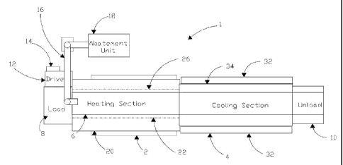
In Figure 1 a typical layout of a furnace 1 in accordance with the
invention is illustrated. As can be seen the furnace 1 comprises two
primary sections, a heating portion 2 and a cooling portion 4. A steel belt
6 is provided and arranged to pass thorough the heating portion 2 and the
cooling portion 4. The belt is continuous and extends between a loading
area 8 and an unloading area 10. A conventional drive means 12 is
provided adjacent the loading area 8 and is arranged to drive the belt such
that material loaded on the belt 6 passes through the heating portion 2
and the cooling portion 4. The drive means 12 has a control mechanism
14 that controls the rate of drive of the belt 6. The control mechanism 14
may be continuously variable or may drive the belt 6 at one of a number
of predetermined speeds. The speed of the belt may be varied in
accordance with a number of factors. The belt speed is varied depending
on material thickness and complexity, the thicker the material the slower
the belt.
The heating portion 2 is provided with at least one exhaust channel 16
connecting the heating portion to an abatement unit 18. The abatement
unit comprises burners arranged to combust fumes passing through the
exhaust channel and into the abatement unit. The abatement unit 18 is a
unit, such as that produced by Compact Power Limited, arranged to burn
off fumes and will not be further described as the form and arrangement
will be well known to a man skilled in the art. The abatement unit 18 is
arranged to burn off the fumes at around 1200 C. Other temperatures may
be used depending on the composition the fumes. Alternative units may be
substituted to process the fumes in alternative ways. Such alternative units
are well understood to the man skilled in the art.
The heating portion 2 comprises a first heating portion including a heating
tunnel 20 and a second heating portion 22. The heating tunnel 20 is
illustrated in Figure 2 and comprises a throat 24 and a passage 26 having
CA 02714172 2010-07-06
WO 2009/090264
PCT/EP2009/050564
32
the belt 6 running along a base of the passage. The passage extends
between the throat and an entry 27 and has a sloping roof increasing in
height from the throat 24 to the entry 27 to the second heating portion 22.
The throat 24 is 0.25m high and is 2m wide. The height of the passage in
this is the same through the passage and at the entry 27 to the second
heating portion. The second heating portion has a chamber 28 having a
base 30 and a roof 31 that is substantially the same height from the base
30 throughout the chamber of the second heating passage. The belt 6 is
provided and also runs along the base 30 of the chamber 28.
The chamber 28 is connected to the cooling portion 4 and the belt runs
through the chamber 28 into the cooling portion 4. The cooling portion 4
is water cooled by means of conventional water jackets 32 provided on an
exterior 34 of the cooling section 4. As the location and operation of the
cooling jackets is conventional these will not be further described since
they will be well known to a man skilled in the art. Alternative means of
cooling the cooling portion may be substituted.
The belt 6 passes from the cooling portion into the unloading section 10.
Material 36 (schematically indicated in Figure 2) to be recycled is
prepared if necessary before loading onto the belt 6 in the loading area 8.
The material 36 is subjected to minimal preparation before being loaded
onto the belt. It may be cut into sections such that each section is less
than 0.25m high and 2m wide. The length of each section is not critical
but is conveniently less than 2m for ease of handling. These dimensions
are a result of the dimensions of the throat of the furnace. It will be
understood that the furnace may have a throat 24 having different
dimensions in which case the maximum dimensions of the material to be
recycled will change accordingly. A particular advantage of the invention
CA 02714172 2010-07-06
WO 2009/090264
PCT/EP2009/050564
33
is that material to be recycled needs little if any preparation before being
loaded onto the belt 6.
The material to be recycled comprises carbon fibres in a resin composite.
The resin composite may vary with the particular product being recycled.
It is preferable to identify the resin component and the likely
decomposition products before the material is loaded onto the belt 6 to be
recycled. The temperature of the heating tunnel and/or the second heating
portion may be altered as a consequence of the particular resin
component. Alternatively, or as well, the drive speed of the belt may be
varied.
Once the material has been loaded onto the moving belt 6 the material
passes into the throat 24 of the first heating portion and into the passage
26. In the passage 26 the temperature is in the region of 450 C to 500 C.
The temperature may be changed depending on the material to be
recycled. The drive speed may also be varied so that a dwell time of the
material in the heating tunnel is controlled to a desired time depending on
the material and the temperature of the heating tunnel. A thickness of the
material to be recycled may be measured and the dwell time may be
increased if the thickness is greater than say lOmm.
As the material passes through the throat of the tunnel and into the
heating tunnel the material rapidly rises in temperature and resin in the
material begins to decompose emitting fumes from the material. These
fumes rise from the carbon fibre material and are contained within the
heating tunnel. The rate of "gassing off" is rapid at the temperature in the
heating tunnel and the atmosphere is almost instantaneously filled with
fumes. These fumes comprise of organic compounds and it is believed
that there is little or no free oxygen in the decomposition. Consequently
the fumes in the tunnel contains substantially no oxygen over the material
CA 02714172 2010-07-06
WO 2009/090264
PCT/EP2009/050564
34
once gassing off has started. The heating tunnel may have a sloping roof
increasing in height from the throat to the entry to the second heating
portion or the height may be constant. Means of controlling the
atmosphere are provided in the heating tunnel. These will now be further
described.
A first fan of may be conventional nature provided adjacent the entry to
the second portion. In the preferred embodiment only one fan is used in
the abatement unit, and is the only fan used for atmosphere control.
An entry 38 is provided in a side wall of the first portion of the furnace
and connects the passage 26 to the exhaust channel 16 leading to the
abatement unit 18. In the example shown the entry 38 is in a side wall.
The entry may also be provided in the same wall as the throat or may
comprise a part of the throat opening.
Pitot tubes 39 are provided which measure the differential pressure and
provided a visual readout. If the pressure goes above -lmbar the furnace
atmosphere will contain a greater degree of oxygen, ideal pressure should
be -lmbar resulting in a slight movement of the atmosphere towards the
abatement unit.
An oxygen meter 40 is provided on an opposing wall to the entry 38. The
oxygen meter monitors the oxygen content in the first portion of the
furnace adjacent the throat 24. The monitor operates continuously but
may be arranged to sample the atmosphere on a regular basis. The period
between samples may range from 1 sec to 5 minutes. A conventional
oxygen monitor is used.
The only fan in the preferred embodiment is provided in the abatement
unit and operates to draw fumes from the first portion of the furnace into
the abatement unit.
CA 02714172 2010-07-06
WO 2009/090264
PCT/EP2009/050564
Means of monitoring the pressure in the first portion are provided
adjacent the second heating portion 28 and adjacent the entry to the
exhaust channel. The pressures are monitored and transmitted to a control
5 unit, not shown, which controls operation of the first and second fans in
order to maintain a pressure differential of around -lmbar. An output
from the oxygen monitor is also inputted to the control unit. If the oxygen
content of the atmosphere deviates from a desired level of between 1%
and 5% (v/v) the flow rate of the fan may be varied to return the oxygen
10 content to the desired level by decreasing the flow of fume into the
exhaust channel in order to decrease the oxygen content in the atmosphere
or by increasing the flow rate in order to increase the oxygen content in
the atmosphere.
15 At least one temperature monitor is also provided to monitor the
temperature in each of the heating portions and also in the cooling
portion. Preferably thermocouples are fixed throughout the length of the
heating zone above and below the belt. Outputs from the or each
temperature monitor may also be input into the control means. The
20 control means may be adjacent to the furnace or may be remote
therefrom. Outputs from the monitors may be transmitted to a remote
location and control instructions may be transmitted from the remote
location to the furnace.
25 Temperatures of each portion are maintained in the ranges discussed
previously. Ideally the first portion has a temperature of 425 C to 475 C.
The second portion 28 is maintained between 550 C and 600 C. If the
temperature is too high the carbon fibres may oxidise in too short a time.
30 The dwell time is also controlled and may be varied depending on the
temperatures of the heating portions. As the temperature is increased the
CA 02714172 2010-07-06
WO 2009/090264
PCT/EP2009/050564
36
dwell time may be decreased in order to avoid undesirable oxidation of
the fibres.
An extract fan is provided in the second heating portion 28 and is
connected to another exhaust pipe (not shown) communicating between
the second heating channel and the abatement unit. A small amount of
further fume may be generated in this second heating portion and is also
burnt off in the abatement unit.
The cooling portion 4 is approximately 8m long and provides a region in
which the carbon fibre may be slowly cooled to ambient temperature to
make the material handleable at the end of the process. The length of the
cooling portion may be varied depending on the speed of the belt.
The cooling portion is conventional and the form may be altered or
adapted in ways obvious to a man skilled in the art.
Once the carbon fibre material has cooled it enters the unloading area 10
and is unloaded from the belt. The material is collected in hoppers and
transported to a finishing area. The material may be finished by milling
the fibre to between 200 and 300 microns or the fibres may be chopped to
lengths between 3 and 150mm.
Some material may be recycled without chopping or milling. A particular
example is woven pre-preg rolls in which the resin has become out of
date. The rolls may be passed through the furnace and then be re-
impregnated with resin without compromising the woven structure of the
cloth.
An alternative furnace will now be described with reference to Figure 4.
The furnace 100 comprises a single chamber 102. A gate or throat 104 is
CA 02714172 2010-07-06
WO 2009/090264
PCT/EP2009/050564
37
provided at a first end of the chamber 102. A belt 106 passes from a
charging table 108 through the throat 104 and into the chamber 102.
Material to be recycled is place on the belt 106 at the charging table 108.
As before the material to be recycled is generally untreated before being
placed on the belt. In some cases it may be necessary to cut the material
to reduce overall dimensions so as to pass through the throat. In this
furnace the gate dimensions can be enlarged or reduced. The gate can be
enlarged in order to allow larger items of material to be recycled to pass
through the gate. It is also advantageous to be able to reduce the
dimensions of the gate in order to control a flow of air entering the
chamber 102 by means of the gate. Typically the throat is approximately
six inches in height and 2 m across. It is possible to reduce the height of
the throat by lowering an internal gate in front of the throat or by using
variable doors.
After passing through the chamber 102 the belt enters a cooling portion
110. The overall length dimensions of the chamber 102 and cooling
portion 110 are similar to those of the furnace previously described.
The chamber 102 is open and air can enter the chamber by means of the
gate 104 and the cooling portion 110. The belt moves at several meters
per minute and it is envisaged that speeds up to 8m per minute could be
used. A typical belt speed is from 1 to 4 metres per minute.
In this furnace the chamber 102 can be considered to comprise of four
zones A to D. Zones A and D are buffer zones and are maintained at a
temperature which is below that of Zones B and C which comprise first
and second heating portions. Typically the temperature at the entrance of
Zone B, the first heating portion of the chamber, is maintained at from
425 to 450 C. The exact temperature of Zone B may be varied depending
on the thickness of the material to be recycled and the composition of the
CA 02714172 2010-07-06
WO 2009/090264
PCT/EP2009/050564
38
resin in the composite material to be recycled. Zone B may have a higher
temperature as it approaches Zone C, for example Zone B may be ramped
from a temperature at its entrance of from 425 to 450 C to a temperature
at its exit of from 500 to 650 C. Zone C comprises a second heating
portion and is generally maintained at a higher temperature than that of
the entrance to Zone B. It has been found that a temperature of about
600 C to 650 C is usually suitable. Polishing or removal of char generally
occurs in Zone C. The exact temperature of Zone C may be varied to
control the quantity of char remaining on the carbon fibre. Typically
Zone C is maintained at a temperature of between 500 C and 700 C. The
temperature of zone C is conveniently set to 620 C. The buffer zones A
and D are maintained at a temperature from 200 C to 400 C. As
described above, it may be desirable to maintain at least some char on the
recycled carbon fibre depending on the proposed use of the recycled
carbon fibre.
Heating elements (not shown) are provided throughout the chamber 102 in
order to provide heat input into the chamber as required. In
this
embodiment the heating elements are electrical elements but it will be
understood that alternative sources of heat can be used in the chamber.
An example of an alternative source of heat is a gas burner.
A number of temperature sensors are provided in the chamber. The
temperature sensors are located in each zone. Two temperature sensors
are provided in each zone in this furnace. In this furnace the temperature
sensors are located adjacent to heating elements provided in the furnace.
The or each temperature sensor is arranged to output data indicative of
the temperature to a controller (not shown).
A number of exhaust vents 112 are provided in the chamber. In this
furnace an exhaust vent is provided in each zone. More than one exhaust
CA 02714172 2010-07-06
WO 2009/090264
PCT/EP2009/050564
39
vent may be provided in each zone or it may not be necessary to provide
an exhaust vent in each of the zones. Each of the exhaust vents is
connected to an abatement unit. In this furnace the abatement unit 116
comprises burners 114 which combust the waste gases from the chamber.
Further burners are provided but are not indicated in Figure 4. The
abatement unit is conventional in the burning of gases to reduce the
environmental effect of gases emitted from the furnace. In this furnace
the abatement unit burners burn the gas at between 800 C and 1200 C.
The waste gases are transferred to a chimney (not shown) to cool and
release gases to the atmosphere. Release of gases to the atmosphere from
the chimney creates a natural draw which moves gases through the
abatement unit and when the exhaust vents 112 are open also draws fume
from the chamber 102 into the abatement unit 116.
The exhaust vents are provided with control mechanisms that control
opening and closing of the vents. The vents may be opened to a degree
that may vary between 0 and 100 . The control mechanism may be set
to open the or each vent for a period that varies between 0 and 30
seconds. The vents may be arranged to be open for a longer period of
time if the conditions in the chamber require it in order to maintain the
correct balance of fume and air. When the or each exhaust vent is open,
the draw from the chimney draws fume from the chamber into the
abatement unit. Thus fume is removed and air from outside the chamber
is drawn into the chamber by means of the gate and the cooling portion.
As air is drawn into the chamber the percentage of oxygen in the
atmosphere is increased and further combustion of the resin and
decomposition products is encouraged.
An oxygen sensor is provided in each zone. In this furnace the oxygen
sensors are provided in a central portion of each zone but in other designs
the sensors may be located at a beginning of each zone. The oxygen
CA 02714172 2010-07-06
WO 2009/090264
PCT/EP2009/050564
sensors can be arranged to sample the atmosphere continuously or
periodically and this may be set by the controller. It is desired to maintain
the percentage of oxygen in the atmosphere in less than stoichiometric
amounts of oxygen, so as to achieve chemical decomposition. In other
5 words, the amount of oxygen present in the atmosphere of the first
heating portion of the furnace is less than 100% of the amount required
for combustion.
The proportion of oxygen in the atmosphere in the first heating portion of
10 the furnace is preferably controlled to less than 16% (v/v), e.g. from
0.5
% (v/v) and up to 16% (v/v). It is generally preferred to maintain the
percentage of oxygen at less than 5% (v/v) but greater than 1% (v/v). The
exact percentage of oxygen in the atmosphere may vary with the
composite material to be recycled.
If the oxygen content of the atmosphere deviates from a desired level of
between 1% and 5% (v/v) the exhaust vents may open for a period of
time to return the oxygen content to the desired level. The vents may be
closed to decrease the flow of fume into the abatement unit in order to
decrease the oxygen content in the atmosphere or may be opened to
increase the flow rate to the abatement unit so increasing the oxygen
content in the atmosphere.
When the exhaust vents are closed, fume is not removed from the
chamber and air is not drawn into the chamber from outside the furnace.
Fume builds up in the chamber and reduces the percentage of oxygen in
the atmosphere of the chamber. Decomposition of the resin continues but
there is reduced combustion of the decomposition products and reduced
combustion of the carbon fibre in the material.
CA 02714172 2010-07-06
WO 2009/090264
PCT/EP2009/050564
41
Opening and closing of the vents is performed to ensure that the
percentage of oxygen in the atmosphere is maintained in the desired range
to enable decomposition and combustion of the fume to occur but to
reduce oxidation of the carbon fibre. The natural draw of the chimneys
removes the fume without the use of fans or other fluid transmission
apparatus to move air into the chamber. Sufficient draw on the chamber
must be provided to prevent fume from being released from the chamber
by the gate or the cooling portion.
Pitot tubes are provided, as before, which measure the differential
pressure and provided a visual readout. If the pressure goes above -lmbar
the furnace atmosphere will contain a greater degree of oxygen, ideal
pressure should be -lmbar resulting in a slight movement of the
atmosphere towards the abatement unit.
In this embodiment the abatement unit is located on and around the
chamber 102, rather than being provided as a separate unit. Accordingly
there is an advantageous exchange of heat between the chamber and the
abatement unit which reduces the energy required to process the
composite material. The abatement unit typically uses gas burners to
raise the temperature of the fume and combust the gases therein. The gas
burners are provided with a supply of air and fans supply the burners with
the air in a conventional manner.
Material on the belt 106 passes through the gate and into zone A. The
temperature of the material is rapidly raised to the temperature of zone A
which is generally between 200 and 300 C and the material passes into
zone B, the first heating zone. The
temperature of zone B is
approximately 425-450 C. As the material reaches this temperature,
decomposition of the resin begins to occur and combustion of the
decomposition products with the oxygen in the atmosphere also occurs. It
CA 02714172 2010-07-06
WO 2009/090264
PCT/EP2009/050564
42
has been found that a visible flame front 118 occurs in the carbon fibre
material. The flame front 118 is generally linear and extends across the
belt. The width of the flame front, i.e. the extent to which the flame
front extends in the direction of travel of the belt, may be between 5cm
and 20cm depending on appropriate adjustment of belt speed, temperature
and percentage of oxygen in the atmosphere. An exact width of the flame
front varies with the temperature and speed of movement of the belt.
These variables can be adjusted to control the forward width of the flame
front to a desired width. It will be understood that if the flame front is
too wide, that is the size of the flame front is too great in the direction of
travel of the belt, then unwanted combustion of the carbon fibres can
occur. On the other hand, if the flame front is not wide enough it is
found that not all the resin is decomposed and further treatment of the
composite material is required.
It is believed that the presence of a flame front is unique to the instant
invention since in other recycling methods the atmosphere is substantially
inert so that no combustion can occur and indeed the risk of an explosion
has taught that oxygen should be removed from the atmosphere. Other
known methods raise the temperature very slowly and it is thought that
decomposition occurs without active combustion and the presence of a
flame. It has been found that as the composite material passes linearly
through the flame front all the material is consistently raised to a similar
temperature and the resulting carbon fibre has consistent physical
properties. Other methods have been found to have produced material
that may have variable properties which is not as desirable.
Once the fume is generated the atmosphere is controlled as described
above. The material on the belt passes through the first heating portion
comprising zone B and enters the second heating portion of zone C. The
second heating portion is not physically separated from zone B but is
CA 02714172 2010-07-06
WO 2009/090264
PCT/EP2009/050564
43
maintained at a higher temperature, typically 600 to 650 C. Relatively
fewer fumes are generated in this portion and the percentage of oxygen in
the atmosphere is higher than that in the first heating zone. Further
combustion occurs in this zone and the char remaining on the carbon fibre
is burnt off. A bluish flame can be seen on the carbon fibre material as
the char is burnt off and a clean carbon fibre is produced.
The temperatures of the first and second heating portions are higher than
the corresponding temperatures of the first embodiment described. The
speed of the belt is greater and so the dwell time in the first and second
heating portions is reduced. In general a dwell time of about 4 to 6
minutes in the first heating zone and about a further 4 to 6 minutes in the
second heating zone has been found to produce desired results, although
even lower dwell times than this may be suitable.
The material passes from the second heating portion, zone C, to zone D
which is a buffer zone and cooling of the material commences. Zone D is
maintained at a temperature between 200 and 400 C. The atmosphere in
zone D is relatively clear of fume. The belt transports the material from
zone D into the cooling portion 110 which is cooled in a conventional
manner. The belt 106 arrives at 120 at a discharge table 122. The belt
passes below a suction unit 124 which operates to remove any fly from
the recycled material. The fly is formed by carbonised char and carbon
fibres and is removed and filtered to prevent contamination of the
surrounding area. It has been found that there is relatively little fly
produced compared to existing methods, as the material is largely uncut
before entering the furnace and is transported on the belt without being
cut, abraded or tumbled. The resulting carbon fibre in the recycled
material is consequently of higher cosmetic quality than that resulting
from methods in which the carbon fibre material is cut or milled before
CA 02714172 2010-07-06
WO 2009/090264
PCT/EP2009/050564
44
treatment or is rotated, crushed or tumbled or impacted in passing around
bends in the recycling process thus damaging the fibre.
As has been referred to above, the composite carbon fibre material can be
delivered from the end of the belt into receptacles. Alternatively if
laminar material has passed through the furnace it can be removed from
the belt and manually delaminated.