Note: Descriptions are shown in the official language in which they were submitted.
CA 02714206 2010-08-05
W02009/097969
PCT/EP2009/000403
METHOD AND APPARATUS FOR RECEIVING FINE-GRAINED TO COARSE-
GRAINED SOLIDS FROM A VESSEL AND TRANSFERRING THEM TO A HIGHER-
PRESSURE SYSTEM
The invention relates to an apparatus and a method for receiving
fine-grained to coarse-grained solids from a vessel and
transferring them to a higher-pressure system by way of a
shutoff mechanism, whereby the vessel is equipped with devices
for supplying the solid and for supplying gases to raise the
pressure in the vessel, as well as with devices for pressure
equalization during filling and emptying, whereby the vessel
bottom is formed as a funnel for supplying the shutoff
mechanism.
Numerous practical cases exist in which it is necessary to
supply a system with fuels, for example from the surroundings,
which fuels will be processed at a pressure much higher than the
ambient pressure in the further course of the process.
Such a situation occurs, for example, during thermal conversion
of solid fuels, such as different coals and also peat,
hydrogenation residues, residual substances, wastes, biomasses,
fly ash or the like, where these terms are also to be understood
CA 02714206 2010-08-05
W02009/097969
PCT/EP2009/000403
- 2 -
as all mixtures of such substances. Examples of conversion
processes of this type include high-pressure incineration, high-
pressure gasification, fluidized-bed processes and carrier-gas
processes.
In such processes, for example in high-pressure gasification of
coal dust, pressures up to 45 bar are not unusual, and so the
substances to be converted would have to be brought up to this
pressure before gasification, whereby higher pressures also lead
to greater system capacities.
Greater system capacities mean larger amounts of fuels to be
transported, whereby vice versa, larger amounts of ash or slag
have to be managed at the same time. In this connection, it must
be kept in mind that geometric limits are imposed on such
sluices or sluice vessels by the behavior to be expected of the
bulk material or by discharge mechanisms, connecting lines,
fittings or the available localities. In this connection, an
increase can be achieved, for example, in that the number of
vessels and/or the throughput during the sluicing operation is
increased.
Several solutions addressing this problem already exist; for
CA 02714206 2010-08-05
W02009/097969
PCT/EP2009/000403
- 3 -
example, WO 2004/085578 Al discloses a sluice vessel provided
internally in the conical vessel part with gas-supplying
elements, by way of which the vessel is brought up to the target
pressure. DE 41 08 048 discloses similar elements in the conical
part of the pressure dome, for the purpose of achieving
fluidization of the solid bulk material in order to improve
pneumatic conveyance out of the pressure dome. In WO 98/11378 it
is proposed that gas be supplied by installing porous elements
in the outlet cone of the silo in order to permit a more uniform
flow of material. A similar feature is described in US
4,941,779.
Apparatuses inside vessels for the purpose of simplifying the
discharge of powdered material are also known, for example, from
DE 11 30 368 A, DE 195 21 766 A, GB 940 506 A or US 2,245,664 A,
whereby the auxiliary means are used exclusively to supply
fluidizing air.
It is also known that discharges of bulk goods from vessels can
be achieved by way of worm conveyors or similar elements.
The object of the invention is to provide an apparatus for
discharging solids, which apparatus can be pressurized with
27046-50 CA 02714206 2014-08-07
- 4 -
selective priming of the vessel, while avoiding compression of
the bulk material and safely assuring transportation of the
solids even in the case of difficult bulk material, along with
= great flexibility in the use of different bulk materials during
operation and the highest possible mass flow toward the
receiving vessel.
With an apparatus of the type mentioned above, this object is
achieved, according to the invention, in that at least one
vertically aligned central tubular member (central tube) open at
= the top and bottom as well as gas-supply devices for admitting
gas to the vessel bottom and/or the central tube in order to
generate a flow of solids in the central tube is provided inside
the vessel above the shutoff mechanism in the direction of
gravity and spaced apart from it.
It has been shown that the provision of a central tube in
combination with gas-supply devices leads to very good
conditions for transfer of the solid from the sluice vessel into
a downstream pressure vessel. Among other advantages, this leads
to the achievement of very short cycle times.
Further embodiments of the invention are specified,
27046-50 CA 02714206 2014-08-07
- 5 -
whereby it may be provided that the central
tube is of double-wall construction and has gas applied to it by
at least one gas-supply line, whereby the tube wall is provided
with gas-outlet apertures.
The possibility of supplying gas both by way of the walls of the
central tube and by way of the vessel walls, especially the
vessel bottom, leads to several advantages, both in the phase of
filling of the vessel with material to be transferred and in the
discharge phase, when the material is being transferred under
higher pressure.
An important embodiment of the invention consists in that the
central tube is equipped with inlet apertures, distributed over
its length, for the solid, thereby making it possible for the
solid to flow into the interior of the tube. In the process,
because the central tube is equipped with outwardly directed
and/or inwardly directed gas-outlet apertures, as is also
provided by the invention, targeted flow behavior of the solid
in the interior of the vessel can be achieved, in accordance
with the wishes of the operator.
A further practical embodiment of the invention consists in that
CA 02714206 2010-08-05
WO 2009/097969
PCT/EP2009/000403
- 6 -
annular chambers are formed by partition walls in the double-
walled central tube, whereby each annular chamber is equipped
with at least one gas-supply line, the solid-inlet apertures
into the interior of the central tube are provided between the
annular chambers, and the diameter of the annular chambers may
be the same or different. By the fact that the individual
annular chambers are provided with individual gas supplies, it
is possible, for example, to improve the incoming flow of solid
from outside to inside through the corresponding inlet aperture
for solids, by way of the end faces of an annular chamber
disposed at a higher level.
In this way, it is also possible to provide annular chambers of
progressively smaller diameter in the manner of a cascade in the
direction of gravity from top to bottom, or to construct an
alternation of annular chambers with small and large diameter,
or to form the annular chambers themselves as funnels, for
example with the smaller diameter disposed lower in the
direction of gravity.
The invention also provides a multiple distribution of gas-
outlet apertures, for example in the vessel walls, the central-
tube walls, the connecting nozzles assigned to the sluice and
ak 02714206 2014-08-07
27046-50
- 7 -
other similar locations, whereby in particular, it may also be
provided that the outlet apertures are equipped with
appropriate elements for guiding the gas flow, in order to form
predefined flows, such as tangential flows.
It may also be provided that a protective/deflecting hood is
disposed above the tube in order to deflect the upwardly
directed flow of solids during priming of the vessel and to
prevent the tube from filling with solid during the filling
operation.
According to one aspect of the present invention, there is
provided apparatus for receiving fine-grained to coarse-grained
solids from a vessel and transferring them to a higher-
pressure system by way of a shutoff mechanism, whereby the
vessel is equipped with devices for supplying the solid and for
supplying gases to raise the pressure in the vessel as well as
with devices for pressure equalization during filling and
emptying, whereby the vessel bottom is formed as a funnel for
supplying the shutoff mechanism, wherein at least one
vertically aligned central tubular member (central tube) open
at the top and bottom as well as gas-supply devices for
admitting gas to the vessel bottom and/or the central tube in
order to generate a flow of solids in the central tube are
provided inside the vessel above the shutoff mechanism in the
direction of gravity (g), and spaced apart from it.
According to another aspect of the present invention, there is
provided method for receiving fine-grained to coarse-grained
solids from a vessel and transferring them to a higher-pressure
system, whereby the vessel is equipped with devices for
supplying the solid and for supplying gases to raise the
CA 02714206 2014-08-07
27046-50
- 7a -
pressure in the vessel as well as with devices for pressure
equalization during filling and emptying, wherein at least one
vertically aligned central tubular member (central tube) is
provided inside the vessel above the shutoff mechanism in the
direction of gravity, at a distance from it, whereby the
filling of the receiving vessel, which initially is under
ambient pressure, with solid takes place in the annular space
formed between the inside wall of the vessel and the outside
wall of the central tube and a gas is injected in the region of
the shutoff mechanism during the filling operation, whereby
pressure equalization is achieved by way of a gas
supply/removal controller, and subsequently, the vessel is
brought up to the higher system pressure prevailing on the
other side of the shutoff mechanism by supply of gas, whereby
the gas is injected in such a way that an upwardly directed
flow of solid is formed in the central tube.
27046-50 CA 02714206 2014-08-07
- 8 -
Examples of the invention will be explained below, on the basis
of the drawing. This shows, in
Fig. 1 a schematic diagram of a sluice vessel according to the
invention,
Fig. 2 in a similar representation, a schematic section through
a sluice vessel according to the invention, with central
tube,
Fig. 3 a slightly enlarged detail drawing of part of the
central tube, and
Fig. 4 an enlarged schematic detail section of the gas supply
in the nozzle connected to the shutoff mechanism.
CA 02714206 2010-08-05
=
WO 2009/097969 PCT/EP2009/000403
- 9 -
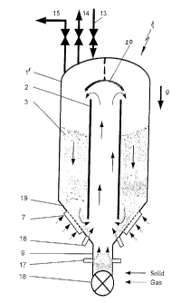
The apparatus denoted as a whole by 1 is illustrated
substantially schematically in Fig. 1. This apparatus 1 consists
substantially of a sluice vessel l', in the interior of which a
tube - referred to hereinafter as central tube 2 - is provided.
This vessel l' is provided with a bed 3 of solids, whereby the
arrows in Fig. 1 illustrate a flow pattern that develops during
priming, or in other words pressurization, of the vessel by
means of compressed air.
In Figs. 1 and 2, the flows of solid are indicated with solid
arrows, while the dotted arrows represent the gas flow. Another
downwardly pointing arrow indicating the direction of gravity
"g" is shown on the right side of the figures.
In the example of Fig. 1, gas-supply units 7 are provided in the
vessel bottom, which is denoted by 19, and gas supplies 16 are
provided in the transition region to the outlet nozzle 9, which
region leads to a shutoff mechanism 18, whereby additional gas
supplies 17 are provided at the outlet nozzle 9 for the purpose
of generating gas flows, which are capable, during filling of
the vessel, for example, of generating a flow of solids that is
CA 02714206 2010-08-05
W02009/097969
PCT/EP2009/000403
- 10 -
offset from the center of the central tube 2 and is directed
upward in the central tube 2, as indicated by arrows in Fig. 1.
In order to prevent penetration of solid from above into the
central tube during the filling operation, a deflecting or
protective hood can be provided above the central tube, as is
schematically illustrated and denoted by 20 in Fig. 1. The gas
supply in the tube nozzle 9 is illustrated in more detail in
Fig. 4.
Reference numerals 14 and 15 denote equalizing-gas lines, by way
of which, for example, the air present in the vessel can escape
during filling, thus allowing the pressure in the vessel to
remain constant during this operation.
In the illustrative example of Fig. 2, the central tube 2 is
shown in simplified form as a double-walled tube having a tube
composed of segments, wherein the individual tube segments,
denoted by 8, are spaced apart from one another, in each
instance, in such a way that inlet apertures 5 are formed for
the solid or for an appropriately guided carrier gas during
emptying of the vessel. This emptying situation is depicted in
Fig. 2, whereby the stream of solids is again indicated by solid
small arrows while the gas flow is represented by dotted arrows.
27046-50 CA 02714206 2010-08-05
WO 2009/097969
PCT/EP2009/000403
- 11 -
The tube segments 8 together with their inner tube jacket 11
have gas-outlet apertures, which are denoted by 12, on their
outer tube jacket 10.
In the example of Fig. 2, gas-supply units 7 are provided not only
in the funnel region of the vessel 1', but also in the
cylindrical peripheral region. These gas-supply units are
denoted by 6 in Fig. 2.
By way of supply lines 4, gas can be admitted to the annular
spaces of central tube 2 between outer tube jacket 10 and inner
tube jacket 11, whereby a common gas supply can be provided
(Fig. 2) or also, individual gas supplies can be provided for
each tube segment, as indicated in Fig. 3.
The principle of operation of the apparatus according to the
invention and of the method of procedure according to the
invention is the following:
By way of the solid supply 13, the vessel 1' is first filled
with solid in such a way that the central tube, which is
disposed above the shutoff mechanism 18, in relation to the
funnel-shaped bottom of the vessel, is not filled, whereby a
CA 02714206 2010-08-05
. .
WO 2009/097969
PCT/EP2009/000403
- 12 -
certain proportion of solids piles up above the shutoff
mechanism. This situation is illustrated in Fig. 1.
If the vessel is now primed, gas is simultaneously supplied
under individual control by way of the segments 8 of the central
tube 2 and by way of the gas-supply units 6 and 7 disposed on
the vessel wall and/or on the vessel bottom, as well as by way
of the gas supplies 16 and 17, in such a way that the ascending
flow of solids illustrated in Fig. 1 is developed in the
interior of the central tube, whereby care is also taken to
ensure that the region immediately upstream from the shutoff
mechanism 18 is fluidized or stirred up by way of the gas-supply
lines 17. For this purpose, the advantageous mode of operation
is such that the main gas supply takes place by way of this gas
supply 17 in the outlet. This results in forced circulation of
solids inside the vessel, thus preventing compacting of the
material that would occur in bulk material at rest.
In Fig. 4 it is indicated that the gas supply 17 can be
configured in such a way that a swirling flow into the
connecting tube nozzle 9 is generated by way of swirl-producing
elements denoted therein by 20 in the gas outlet, which is
denoted by 17', thus ensuring appropriate fluidization of the
CA 02714206 2010-08-05
. .
WO 2009/097969
PCT/EP2009/000403
- 13 -
solid. As indicated in Fig. 4, this gas supply 17/17' can be
configured, for example, as a circumferential annular gap, or
can be provided with further outlet apertures over the
circumference. A special advantage of this configuration
consists in that recirculated dust-laden gas can be used here to
generate flow.
If the vessel is now emptied, gas can be supplied in such a way
that the wall friction in and around the emptying tube and at
the vessel walls is decreased, with the result that the solid
present locally there is loosened. In this way, the supplied gas
accelerates the transfer of the solid into a downstream system
part. Because of the gas supply, the volume cleared by the
exchange of solids is refilled in the vessel. In the process,
excess gas can be supplied, and this is of importance for
avoiding a negative pressure gradient at the outlet aperture 9.
This negative pressure gradient would develop, for example, if
the solid were to run out faster than the cleared volume is
refilled with gas, with the result that gas could flow upward in
the outlet aperture and in a direction opposite to arrow "g",
i.e. against the descending movement of solids, and this would
lead to a distinct hindrance to the discharge of solids.
CA 02714206 2010-08-05
WO 2009/097969
PCT/EP2009/000403
- 14 -
According to the invention, the discharge rate is increased by
virtue of the gas excess.
Since the individual segments can be equipped with separate gas
connections, the possibility also exists of admitting gas
individually to the individual segments 8 and thus controlling
the flow of solids in targeted manner. The segment-wise addition
of gas therefore permits a best possible distribution of gas in
the solid bulk material, thereby making it possible to achieve
improved fluidization of even difficult products during the
discharge operation.
Naturally, the described exemplary embodiment of the invention
can be further modified in numerous respects without departing
from the basic idea. Thus the invention is not restricted to
providing only a central tubular member, but instead the cross-
sectional shape of this member may also differ from the tubular
shape, and also more than one such member may be provided
parallel next to one another, along with further similar
options.
CA 02714206 2010-08-05
WO 2009/097969
PCT/EP2009/000403
- 15 -
List of reference numerals:
1 Sluice vessel
2 Central tube
3 Solid bulk material
4 Gas supply lines
Lateral inlet apertures for solids
6 Gas-supply unit
7 Gas-supply unit
8 Segments/annular chambers
9 Tube nozzles
Outer tube jacket
11 Inner tube jacket
12 Gas outlet
13 Supply of solids
14 Equalizing line
Equalizing line
16 Gas supply
17 Gas supply
18 Shutoff mechanism
19 Vessel bottom
Swirl-producing element