Language selection

Search

Patent 2714257 Summary

Third-party information liability

Some of the information on this Web page has been provided by external sources. The Government of Canada is not responsible for the accuracy, reliability or currency of the information supplied by external sources. Users wishing to rely upon this information should consult directly with the source of the information. Content provided by external sources is not subject to official languages, privacy and accessibility requirements.

Claims and Abstract availability

Any discrepancies in the text and image of the Claims and Abstract are due to differing posting times. Text of the Claims and Abstract are posted:

  • At the time the application is open to public inspection;
  • At the time of issue of the patent (grant).
(12) Patent: (11) CA 2714257
(54) English Title: SYSTEM FOR RELEASE OR MOVEMENT OF A FLUID-DISPENSING HEAD
(54) French Title: SYSTEME DE DEVERROUILLAGE ET DE DEPLACEMENT D'UNE TETE DISTRIBUTRICE DE FLUIDES
Status: Granted
Bibliographic Data
(51) International Patent Classification (IPC):
  • B67D 7/42 (2010.01)
  • B67D 7/74 (2010.01)
(72) Inventors :
  • DROCCO, MARIO (Italy)
  • DROCCO, LUCA (Italy)
(73) Owners :
  • DROCCO, MARIO (Italy)
  • DROCCO, LUCA (Italy)
(71) Applicants :
  • DROCCO, MARIO (Italy)
  • DROCCO, LUCA (Italy)
(74) Agent: RIDOUT & MAYBEE LLP
(74) Associate agent:
(45) Issued: 2017-11-28
(22) Filed Date: 2010-09-02
(41) Open to Public Inspection: 2011-03-04
Examination requested: 2015-08-31
Availability of licence: N/A
(25) Language of filing: English

Patent Cooperation Treaty (PCT): No

(30) Application Priority Data:
Application No. Country/Territory Date
TO2009U000124 Italy 2009-09-04

Abstracts

English Abstract

A system (1) for release or movement of a fluid-dispensing head (2) positioned within a dispenser (6) of fluids; the system (1) houses the fluid-dispensing head (2), which has a plurality of nozzles (3) for the supply of fluids; the system (1) comprises means (7, 10, 20) for release and movement of the fluid-dispensing head (2) configured for enabling movement of the delivery head (2) between a first position of use, in which the nozzles (3) deliver the plurality of fluids into a container (4), and a cleaning position or second position of use (set facing the operator) or third position of use (facing upwards), distinct from the first position of use, in which they are accessible for being cleaned.


French Abstract

Un système (1) de déverrouillage et de déplacement dune tête distributrice de fluides (2) placé à lintérieur dune distributrice (6) de fluides; le système (1) loge la tête distributrice de fluides (2), laquelle possède une pluralité de buses (3) pour lalimentation des fluides; le système (1) comprend des moyens (7, 10, 20) de déverrouillage et de déplacement de la tête distributrice de fluides (2) conçus pour permettre un mouvement de la tête distributrice (2) entre une première position dutilisation, dans laquelle les buses (3) distribuent la pluralité de fluides dans un contenant (4), et une position de nettoyage ou une deuxième position dutilisation (ensemble faisant face à lopérateur) ou une troisième position dutilisation (face vers le haut), distincte de la première position dutilisation, dans laquelle elles sont accessibles pour être nettoyées.

Claims

Note: Claims are shown in the official language in which they were submitted.

CLAIMS
1. A system (1) positioned within an opening/access (6a) of
a paint supply device (6); said system (1) housing a fluid-
dispensing head (2), which has a plurality of nozzles (3) for
the supply of a plurality of fluids of different colours in
controlled quantities into a container (4) set underneath
said fluid-dispensing head (2) on a resting surface (5) of
the paint supply device (6) inside said opening/access (6a);
wherein said system (1) comprises releasing/clamping means
(7, 10, 20) of said fluid-dispensing head (2) configured for
enabling movement of said supply head (2) between a first
clamped position of use, wherein said nozzles (3) supply the
plurality of fluids into a container (4) and a second
extracted position, distinct from said first position of use,
wherein said nozzles (3) are accessible for being cleaned;
wherein said releasing/clamping means (7, 10, 20)
comprises: an L-shaped bracket (7), fixed to said paint
supply device (6), having a first surface (7a) set
substantially vertically and a second surface (7b) set
horizontally, parallel to the ground; a plate (10) housed
on said second surface (7b) of said L-shaped bracket (7)
and having a recess/slot opened on the side facing the
opening/access (6a) of the paint supply device (6) in which
the fluid dispensing head (2) is removably mounted in such
a way as to direct the nozzles (3) downwards towards the
container (4) and also as to enable the manual extraction
of the fluid dispensing head (2); and further comprising
clamping means (20) for clamping said fluid dispensing head
(2) in said recess/slot of said plate (10).
2. The
system (1) according to claim 1, wherein said
clamping means (20) comprise a lever for releasing/clamping

7


said fluid-dispensing head (2).
3. The system (1) according to claim 1 or 2, further
comprising means for blocking delivery of said plurality of
fluids by said nozzles (3) when said fluid-dispensing head is
in said second extracted position.
4. The system (1) according to claim 1, wherein said
clamping means (20) are carried out through a press-block
coupling, i.e., through insertion with contrast into the
recess/slot of the plate (10) itself.
5. The system (1) according to claim 1, wherein said
clamping means comprises an element (20a) for pressing the
fluid-dispensing head (2) into the recess/slot, and a pin
(20b) on which said element (20a) is pivoted at one end
thereof.

8

Description

Note: Descriptions are shown in the official language in which they were submitted.


CA 02714257 2017-01-10
System for release or movement of a fluid-dispensing head
The present invention relates to the field of devices for
dispensing fluids and in particular regards a system for
release or movement of a fluid-dispensing head.
It is known that fluid-dispensing heads are typically mounted
within a closed fluid-supply device. With said dispensing
heads there is hence a simultaneous or sequential
introduction or supply of a given amount of one or more
fluids in a container set underneath them, possibly on a
resting surface.
The fluid-dispensing head typically comprises a plurality of
supply terminals (or nozzles) distinct from one another, each
of which supplies a given fluid, which could, for example, be
a colouring agent, a paint, a solvent, an additive, an
essence or an aroma.
At the end of the supply cycle, in the case where the supply
device is to be left inactive for a given period of time, it
is expedient for the fluid-dispensing head to be cleaned from
fluid residue, which, by hardening in contact with the
external environment over time, may cause clogging of the
outlet holes of the nozzles.
Normally, the fluid-dispensing head is fixed, and the fluid-
outlet holes are set facing downwards.
The cleaning operation is commonly performed manually by an
operator, who is forced to bend down or crouch to bring a
special cleaning tool up to the nozzles.
Consequently, the action of cleaning requires a plurality of
movements by the user, who must clean the fluid-dispensing
head working from beneath upwards. The inconvenience of the
operation of cleaning of a fluid-dispensing head is
encountered in any case even in supply devices of an open
type, in which the structure is not completely enclosed in a
1

CA 02714257 2017-01-10
casing.
US Patent No. 5,690,252 discloses a dispensing system which
utilizes a nozzle assembly including a nozzle block defining
a series of recesses for receiving dispense nozzles. A
resilient clamp is inserted between the nozzles and
compressed so as to expand, clamping the nozzles in position.
US Patent No. 2,835,410 discloses a beverage dispensing
apparatus having a nozzle unit for directing various liquid
ingredients into a cup or other container.
The purpose of the present invention is to provide a system
for release or movement of a fluid-dispensing head that will
be free from the drawbacks described above.
According to the present invention, a system for release or
movement of a fluid-dispensing head is provided as described
herein.
The invention will now be described with reference to the
annexed drawings, which illustrate a non-limiting example of
embodiment thereof and in which:
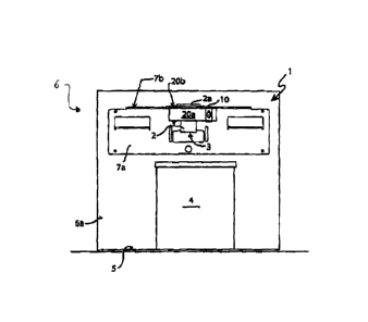
- Figure 1 illustrates a front view of a system for release
or movement of a fluid-dispensing head forming the subject of
the present invention;
- Figure 2 and Figure 3 illustrate, respectively, a first
perspective view and a second perspective view of the system
of Figure 1;
- Figure 4 illustrates a side view of the system of Figure 1.
With reference to Figure 1, designated as a whole by 1 is a
system for release or movement of a fluid-dispensing head.
System for release or movement of a fluid-dispensing head 1
comprises a fluid-dispensing head 2, which is equipped with a
plurality of terminals or nozzles 3 adapted to supply a
plurality of fluids of different colours in controlled
quantities (in terms, for example, of volume or of delivery
time) into a container 4 set underneath said head, on a
2

CA 02714257 2017-01-10
resting surface of a dispenser 6 of fluids.
Said dispenser 6 typically has a supporting structure 5, on
which a user positions the aforesaid container 4.
In detail, nozzles 3 of fluid-dispensing head 2 are arranged
on a common surface adjacent to one another and are each
connected to a respective duct for supply of the fluid to be
dispensed. Substantially, they moreover deliver the
respective fluid in a common direction.
Connected to fluid-dispensing head 2 are, on a top part 2a
thereof, is a plurality of ducts 2b for introduction of
fluids, which are connected to means of their own for supply
of the fluids themselves (not illustrated).
Dispenser 6 of fluids is designed in such a way as to get
fluid-dispensing head 2 to carry out a pre-determined
delivery cycle to obtain a mixture of fluids that, combined
together, will enable supply of a final fluid product, the
colour of which is the one desired by the customer.
System 1 for movement or release of fluid-dispensing head 2
envisages manual extraction thereof and comprises an L-shaped
bracket 7 (head support). In detail, L-shaped bracket 7 is
installed within said delivery device 6 in such a way that
first surface 7a will be substantially set vertically,
whilst, consequently, second surface 7b of L-shaped bracket 7
is set horizontally, parallel to the ground. Fluid-dispensing
head 2, which in this case has a cylindrical shape, is
mounted in a removable way on second surface 7b of L-shaped
bracket 7 through a plate 10 of a slotted type in such a way
as to direct the nozzles downwards, i.e., towards the
container underlying them.
Plate 10 is open on one side in such a way as to enable
extraction of head 2 by a user and, in particular, the
opening side of plate 10 is oriented towards the access of
delivery device 6 in such a way that a user is able to
3

CA 02714257 2017-01-10
extract fluid-dispensing head 2 easily for carrying out a
cleaning operation on its nozzles 3 to clear away fluid
residue. In detail, the slot of plate 10 has a diameter
corresponding to the body of fluid-dispensing head 2; top
part 2a of fluid-dispensing head 2, instead, has a
substantially larger diameter, hence such as to prevent
sliding downwards of the fluid-dispensing head itself. In
detail, clamping of fluid-dispensing head 2 on L-shaped
bracket 7 can be carried out either through a press-block
coupling, i.e., through insertion with contrast into the slot
of the plate itself, or with the aid of means 20 for clamping
fluid-dispensing head 2 in the slot of plate 10.
In detail, said clamping means 20 preferably comprise an
element 20a for pressing fluid-dispensing head 2 into the
slot, and a pin 20b, to which the aforesaid element 20a is
pivoted on an end thereof. Pin 20b has an axis parallel to
the direction along which fluid-dispensing head 2 develops.
Consequently, system 1 for release or movement of fluid-
dispensing head 2 enables the latter to be kept:
- in a first position of use, in which it is constrained to
aforesaid L-shaped bracket 7 and in which it is configured
for delivering fluids into container 4; and
- a second position of use, in which it can be oriented
manually or with some kind of mechanism in the direction of
the operator in such a way as to enable him to clean nozzles
3 at the front.
Alternatively, system 1 for release or movement of a fluid-
dispensing head further comprises a servo mechanism for
rotation of the aforesaid fluid-dispensing head 2 from the
first position of use towards a second position of use, in
which nozzles 3 of fluid-dispensing head 2 are set facing the
operator.
System 1 for release or movement of the fluid-dispensing
4

CA 02714257 2017-01-10
head, in this case, can moreover be configured in such a way
as to enable said fluid-dispensing head 2 to access a third
position of use, as an alternative to or in combination with
the second position of use, in which nozzles 3 -remaining
substantially facing opening 6a of delivery device 6 - are
oriented substantially upwards.
Finally, system 1 for movement or release comprises means for
blocking delivery of fluids from fluid-dispensing head 2;
said means enable a greater safety during the operations of
cleaning of fluid-dispensing head 2, i.e., when it is in the
aforesaid second and/or third position of use. More
precisely, when fluid-dispensing head 2 is in the second or
third position of use, the fluid cannot be supplied by
nozzles 3; instead, only upon reaching the first position of
use can the nozzles resume supply of the fluid.
The means for blocking supply can be of a mechanical type
(for example, valve means, or again means acting on a system
for delivery of the fluid to the nozzles) or of an
electrical/electronic type (such as switches, position
sensors, or equivalent devices, which then act on the data-
processing unit of the supply device) and are typically
associated to element 20a. Alternatively, there may be other
mechanical blocking and safety devices connected to element
20a.
As yet a further alternative, in order to release the
blocking means, the same blocking means can be of a push-
button kind, positioned on the supply device itself. In this
case, when the push-button is depressed, the supply of fluids
from the fluid-dispensing head is blocked, and can be resumed
only upon release of the aforesaid push-button.
The advantages of the system for release or movement of a
fluid-dispensing head so far described are clear in the light
of the foregoing description. In particular, it enables in
5

CA 02714257 2017-01-10
the first place release or movement of fluid-dispensing head
2 either automatically or manually, providing a user with a
greater convenience of the cleaning operation, which no
longer requires any contortion on his part in order to get
underneath the aforesaid fluid-dispensing head 2.
In the second place, system 1 for release or movement of a
fluid-dispensing head moreover prevents, during execution of
the cleaning operation, any possible occurrence of movements
or supplies of fluid that could be dangerous for the operator
himself.
Finally, it is clear that a number of variations, additions,
and improvements, which will be obvious to a person skilled
in the art, may be made to the device described herein,
without thereby departing from the scope of protection of the
annexed claims.
In detail, it will be clear that even in the case where the
fluid-supply device is not partially enclosed in a casing the
effect of greater convenience of cleaning of fluid-dispensing
head 2 is not diminished. In fact, even in the case where all
the structure is completely accessible, in order to clean
fluid-dispensing head 2 it would be necessary to operate in
an uncomfortable position. Consequently, the identification
of a fluid-supply device of a closed type is not to be
understood as in any way limiting for assessing the
convenience of use provided by the system forming the subject
of the present invention.
6

Representative Drawing
A single figure which represents the drawing illustrating the invention.
Administrative Status

For a clearer understanding of the status of the application/patent presented on this page, the site Disclaimer , as well as the definitions for Patent , Administrative Status , Maintenance Fee  and Payment History  should be consulted.

Administrative Status

Title Date
Forecasted Issue Date 2017-11-28
(22) Filed 2010-09-02
(41) Open to Public Inspection 2011-03-04
Examination Requested 2015-08-31
(45) Issued 2017-11-28

Abandonment History

There is no abandonment history.

Maintenance Fee

Last Payment of $263.14 was received on 2023-07-12


 Upcoming maintenance fee amounts

Description Date Amount
Next Payment if standard fee 2024-09-03 $347.00
Next Payment if small entity fee 2024-09-03 $125.00

Note : If the full payment has not been received on or before the date indicated, a further fee may be required which may be one of the following

  • the reinstatement fee;
  • the late payment fee; or
  • additional fee to reverse deemed expiry.

Patent fees are adjusted on the 1st of January every year. The amounts above are the current amounts if received by December 31 of the current year.
Please refer to the CIPO Patent Fees web page to see all current fee amounts.

Payment History

Fee Type Anniversary Year Due Date Amount Paid Paid Date
Application Fee $400.00 2010-09-02
Maintenance Fee - Application - New Act 2 2012-09-04 $100.00 2010-09-02
Maintenance Fee - Application - New Act 3 2013-09-03 $100.00 2013-08-23
Maintenance Fee - Application - New Act 4 2014-09-02 $100.00 2014-08-26
Maintenance Fee - Application - New Act 5 2015-09-02 $200.00 2015-08-06
Request for Examination $800.00 2015-08-31
Maintenance Fee - Application - New Act 6 2016-09-02 $200.00 2016-08-08
Maintenance Fee - Application - New Act 7 2017-09-05 $200.00 2017-08-09
Final Fee $300.00 2017-10-13
Maintenance Fee - Patent - New Act 8 2018-09-04 $200.00 2018-08-08
Maintenance Fee - Patent - New Act 9 2019-09-03 $200.00 2019-08-07
Maintenance Fee - Patent - New Act 10 2020-09-02 $250.00 2020-08-12
Maintenance Fee - Patent - New Act 11 2021-09-02 $255.00 2021-08-11
Maintenance Fee - Patent - New Act 12 2022-09-02 $254.49 2022-07-13
Maintenance Fee - Patent - New Act 13 2023-09-05 $263.14 2023-07-12
Owners on Record

Note: Records showing the ownership history in alphabetical order.

Current Owners on Record
DROCCO, MARIO
DROCCO, LUCA
Past Owners on Record
None
Past Owners that do not appear in the "Owners on Record" listing will appear in other documentation within the application.
Documents

To view selected files, please enter reCAPTCHA code :


To view images, click a link in the Document Description column. To download the documents, select one or more checkboxes in the first column and then click the "Download Selected in PDF format (Zip Archive)" or the "Download Selected as Single PDF" button.

List of published and non-published patent-specific documents on the CPD .

If you have any difficulty accessing content, you can call the Client Service Centre at 1-866-997-1936 or send them an e-mail at CIPO Client Service Centre.


Document
Description 
Date
(yyyy-mm-dd) 
Number of pages   Size of Image (KB) 
Abstract 2010-09-02 1 23
Description 2010-09-02 6 276
Claims 2010-09-02 2 81
Drawings 2010-09-02 4 66
Cover Page 2011-02-10 1 35
Representative Drawing 2011-02-09 1 5
Description 2017-01-10 6 260
Claims 2017-01-10 2 62
Drawings 2017-01-10 4 42
Assignment 2010-09-02 5 155
Final Fee 2017-10-13 1 48
Representative Drawing 2017-10-31 1 4
Cover Page 2017-10-31 1 35
Request for Examination 2015-08-31 1 37
Examiner Requisition 2016-07-11 3 197
Amendment 2017-01-10 25 881