Note: Descriptions are shown in the official language in which they were submitted.
CA 02714361 2010-09-01
COMBINATION VERTICAL ROTARY VANE SUCTION PUMP AND
LIQUID SEPARATOR
BACKGROUND
Technical Field:
[0001] Compact combination suction devices and liquid separators are
disclosed. More
particularly, vertical rotary vane pumps are combined with a liquid/air
separator using a
single motor for providing both suction and liquid/air separation in a compact
design. The
disclosed combination vertical rotary vane pumps and liquid separators are
ideal for use in
dental offices, which typically have limited amounts of space available for
such equipment.
Description of the Related Art:
[0002] Suction tools and devices are commonly used in operating rooms, dental
offices,
and the like, to quickly clear excess liquids during medical procedures. For
instance, a
typical dental office may require a suction device to remove liquids and/or
debris from the
mouth of a patient while examining the patient's teeth or undergoing a
particular procedure in
the patient's mouth. Upstream of the suction device is a separator which is
used to separate
the liquid and solids removed from the patient's mouth before the air flow
enters the suction
device. Various centrifugal and tank base separators are known.
[0003] A typical suction device comprises a pump which compresses air
and.creates a
vacuum or suction. A vacuum may be formed using commonly known pump and/or
blower
systems, such as liquid ring pumps, rotary vane pumps, blower-based systems,
claw systems,
and the like. Although these pumps provide adequate suction and performance,
they still
have their setbacks.
-l-
CA 02714361 2010-09-01
[0004] A liquid ring pump comprises a vaned impeller which rotates within a
cylindrical
housing while a liquid, such as water, is continuously fed into the
cylindrical pump casing.
As the impeller rotates, centrifugal forces cause the liquid to form a
rotating cylindrical ring
against the inner wall of the cylindrical housing. This liquid ring forms a
series of sealed
chambers with the impeller vanes to compress air. Liquid ring pumps are one of
the more
commonly used vacuum pumps installed in dental offices. This is because liquid
ring pumps
are reliable and compact in size. However, liquid ring pumps need a constant
supply of water
to create the sealed compression chambers. This demand for a constant supply
of water
results in significant water utility fees to the end user, inability to comply
with local water
conservation measures and other environmental concerns.
[0005] One alternative to using water consuming liquid ring pumps is to use
rotary vane
pumps. Rotary vane pumps employ a vaned rotor that is disposed within a
cylindrical
housing. The rotor and the cylindrical housing are axially misaligned or
offset such that the
rotor is never centered within the housing. The vanes are configured to be
radially slidable
with respect to the rotor and centrifugal forces bias the vanes radially
outwardly to maintain
contact with the inner wall of the housing. The vanes and the inner wall of
the cylindrical
housing form at least two sealed chambers. Compression is formed when the
respective
volumes of the sealed chambers increase and/or decrease as the off-centered
rotor rotates.
Although rotary vane pumps perform well without requiring a constant supply of
water, they
are larger than liquid ring pumps. Rotary vane pumps also need oil for
lubrication, which
raises additional environmental concerns.
[0006] Regenerative blowers can also be used to create a vacuum or suction for
use with
dental applications. Regenerative blowers include a multi-bladed impeller
which rotates
continuously. A small amount of air slips past one blade and returns to the
base of a
-2-
CA 02714361 2010-09-01
succeeding blade for reacceleration or "regeneration." Regenerative blowers do
not require
water or lubrication. However, regenerative blowers are large and use
significantly more
electricity than liquid ring pumps.
[00071 Claw systems employ rotating claw-shaped lobes which mesh with one
another and
form sealed chambers when fitted within the vacuum housing. Rotating the claw-
shaped
lobes varies the volumes of the respective chambers within the housing to
create compression
or suction. Claw systems do not require water or oil lubrication to maintain
properly sealed
compression chambers. However, claw systems are large and expensive.
[00081 Therefore, there is a need for an improved suction system that provides
comparable
or better performance while overcoming all of the deficiencies associated with
the prior art.
Because modem dental offices are operating on thin margins, capital costs and
operating
costs are primary concerns. Further, as dental offices attempt to operate more
efficiently,
dental offices are becoming smaller, thereby creating a demand for smaller
suction and
separator systems. As a result, there is a need for a cost efficient and
compact suction device
combined with a separator which creates at least as much compression or vacuum
as liquid
ring pumps without requiring water or oil lubrication and which conserves
space.
[00091 While the following discussion will be directed toward suction and
separation
devices for use with dental applications, it will be noted that this
application and the devices
disclosed herein are applicable to various fields beyond that of suction and
separation devices
for use with dental applications, and more generally, can be applied to any
application
requiring solid and/or liquid suction.
-3-
CA 02714361 2010-09-01
SUMMARY OF THE DISCLOSURE
[0010] In satisfaction of the aforenoted needs, a compact suction and liquid
separation
device for use in dental and medical offices is disclosed.
[0011] One disclosed compact suction and liquid separation apparatus comprises
a pump, a
separator and a common motor, vertically stacked with respect to each other.
The pump
comprises a suction inlet and an exhaust outlet. The separator (i.e. an
air/liquid-solids
separator) comprises an inlet configured to receive air and liquids, an air
discharge
configured to route air from the separator to the suction inlet of the pump.
The separator also
comprises a liquids/solids discharge configured to drain liquids and solids
from the separator.
The motor is coupled to both the pump and separator.
[0012] In a refinement, the compact suction and separation apparatus comprises
a noise-
reducing enclosure.
[0013] In another refinement, the pump is disposed above the motor and the
separator is
disposed below the motor.
[0014] In another refinement, the pump comprises a vertically orientated
rotary vane pump.
[0015] In another related refinement, the rotor of the vane pump is
cantilevered or
supported on only one side, the bottom side, of the rotor. As a result, an
upper cap is
removably coupled to an upper surface of the pump rotor and vanes to allow
access to the
vanes for servicing without needing to remove a bearing.
[0016] In another refinement, the air discharge is coupled to the suction
inlet using tubing.
[0017] In another refinement, the rotary vane pump comprises a casing disposed
between
an upper cap and a head plate. The casing accommodates the pump rotor and a
plurality of
vanes'slidably coupled to the pump rotor. The pump rotor is coaxially coupled
to the drive
-4-
CA 02714361 2010-09-01
shaft whereby an upper portion of the drive shaft and rotor are disposed
within the pump
casing but are offset from an axial center of the pump casing. The rotary vane
pump is in a
vertical orientation, whereby the vanes that are slidably coupled to the pump
rotor extend
radially outwardly from the drive shaft and pump rotor when the pump rotor is
rotated within
the casing. The rotor is supported by a bearing disposed below the rotor. To
change the
vanes, only the upper cap needs to be removed.
[0018] In a related refinement, the separator comprises a spinning disk
separator that is
driven by the motor.
[00191 In a refinement, the liquid separator comprises a separator rotor
coupled to the
motor by a drive shaft extending vertically downward from the motor.
[00201 In another refinement, the motor is coupled to a drive shaft that
extends vertically
upward to the pump and vertically downward to the liquid separator.
[0021] A compact combination suction and separation apparatus for use with
dental
procedures is disclosed. The apparatus comprises a vertically oriented rotary
vane pump
comprising a pump casing disposed between a removable upper cap and a lower
head plate.
The head plate comprises a suction inlet and an exhaust outlet in
communication with the
pump casing. The pump further comprises a pump rotor slidably coupled to a
plurality of
vanes. The apparatus further includes a liquid separator comprising a housing
and a separator
rotor. The separator housing is coupled to an inlet for receiving air, liquids
and solids from a
dental suction too], an air discharge coupled to the suction inlet of the pump
and a
liquids/solids discharge. The apparatus further comprises a motor disposed
between the
pump and separator. The motor is coupled to a vertical drive shaft that
extends upward into
the pump casing and that is coupled to the pump rotor. The drive shaft also
extends
downward into the separator housing and is coupled to the separator rotor.
-5-
CA 02714361 2010-09-01
[0022] In a refinement, the pump casing has a vertical axis and the drive
shaft, pump rotor,
separator rotor and separator housing have a common vertical axis offset from
the vertical
axis of the pump casing.
[0023] As shown below, the vane pump, motor and separator are all in generally
axial
alignment with each other to conserve floor space.
[0024] In another refinement, a rotary vane pump can be combined with a
gravity-based
liquid separator. One disclosed liquid separator includes an inlet disposed
between upper and
lower chambers. A flapper valve or baffle separates the chambers. A solenoid
valve or other
suitable valve may be connected to the upper chamber and the lower chamber is
connected to
a bottom reservoir. The bottom reservoir includes an upper level switch and a
lower level
switch.
[0025] In operation, the rotary vane pump runs continuously and therefore the
upper
chamber is under vacuum. With the solenoid in a closed position, the upper
chamber is
isolated from the atmosphere the pressures in the upper and lower chambers is
equalized.
Air/fluids/solids will enter the upper chamber through the inlet and the
fluids/solids will drain
downward to the lower chamber under the force of gravity. Material will
eventually pass
downward to the bottom reservoir. When the upper level switch of the bottom
reservoir is
activated, the system needs to be drained and the solenoid is opened thereby
creating pressure
in the upper chamber and closing the flapper or baffle. With the lower chamber
and bottom
reservoir isolated from the vacuum of the rotary vane pump, material may exit
the system
through a check valve.
[0026] Other advantages and features will be apparent from the following
detailed
description when read in conjunction with the attached drawings.
BRIEF DESCRIPTION OF THE DRAWINGS
-6-
CA 02714361 2010-09-01
[0027] The disclosed suction devices are described more or less
diagrammatically in the
accompanying drawings wherein:
[0028] FIG. 1 is a diagram of a disclosed combination of suction and liquid
separation
apparatus;
[0029] FIG. 2 is a perspective view of a disclosed combination suction and
liquid
separation apparatus;
[0030] FIG. 3 is another perspective view of the apparatus shown in FIG. 2;
[0031] FIG. 4 is an exploded view of the apparatus shown in FIGS. 2-3;
[0032] FIG. 5 is a partial perspective and sectional view of the apparatus
illustrated in
FIGS. 2-4, particularly illustrating the rotary vane pump;
[0033] FIG. 6 is a top perspective view of the rotary vane pump of the
apparatus illustrated
in FIGS. 2-5, with the top cover or upper cap removed thereby exposing the
rotor and vanes;
[0034] FIG. 7 is a partial perspective and sectional view of the apparatus
illustrated in
FIGS. 2-6, particularly illustrating the separator;
[0035] FIG. 8 is a perspective view of the apparatus illustrated in FIGS. 2-7,
equipped with
tubing that connects the separator air discharge and the pump suction inlet;
[0036] FIG. 9 is a perspective view of the apparatus illustrated in FIG. 8 and
disposed
within an outer enclosure for noise reduction;
[0037] FIG. 10 is a perspective view of another combination vertical rotary
vane suction
pump and liquid separator, wherein the liquid separator is gravity-based as
opposed to
centrifugal-based;
[0038] FIG. 11 is another perspective view of the apparatus shown in FIG. 10;
and
-7-
CA 02714361 2010-09-01
[0039] FIG. 12 is a partial sectional view of the apparatus shown in FIGS. 10-
11.
[0040] It should be understood that the drawings are not necessarily to scale
and that the
embodiments are sometimes illustrated by graphic symbols, phantom lines,
diagrammatic
representations and fragmentary views. In certain instances, details which are
not necessary
for an understanding of this disclosure or which. render other details
difficult to perceive may
have been omitted. It should be understood, of course, that this disclosure is
not limited to
the particular embodiments and methods illustrated herein.
DETAILED DESCRIPTION OF THE PRESENTLY PREFERRED EMBODIMENTS
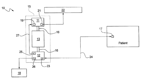
[0041] FIG. 1 illustrates a diagrammatic view of a disclosed combination
suction/liquid
separator 10 as configured for use with a typical dental application. As shown
in FIG. 1, the
combination suction/liquid separator 10 may include a pump 11, a liquid
separator 12 and a
motor 13 for operating the pump 11 and the separator 12. The suction/liquid
separator 10
may optionally include an enclosure 15 so as to reduce noise caused by
operating the device
10. The pump 11 may comprise any pump or blower configuration commonly known
in the
art to create a vacuum or suction, for example, a rotary vane pump. The liquid
separator 12
may be configured to be an automatic separator that uses gravity to passively
separate solids
and/or liquids from air or other gases. Alternatively, the liquid separator 12
may be
configured to include a mechanical or spinning disk separator to actively
separate solids
and/or liquids from air. The motor 13 may be, for example, an induction motor,
or any other
motor appropriate for driving vacuum pumps or blowers. Optionally, the liquid
separator 12
may be associated with a separate motor (not shown), but to conserve space and
save cost, the
motor 13 preferably drives the separator 12 and pump 11 with a common drive
shaft 16.
Suction within the liquid separator 12 may be used to receive any mixture of
solids, liquids
and air resulting from, for example, a dental suction tool 17. As the
solid/liquid/air mixture
-8-
CA 02714361 2010-09-01
reaches the liquid separator 12, solids and/or liquids are separated from the
air and
subsequently disposed of through the drain 18.
[00421 The pump 11 may include at least one suction inlet 19 and at least one
exhaust
outlet 21. If necessary, the exhaust 21 of the pump 11 may be routed to a vent
22, or the like,
leading outdoors. The liquid separator 12 may include at least one inlet 23
and at least two
outlets 25, 26. The inlet 23 of the liquid separator 12 may be configured to
intake any
combination of solids, liquids and air received through the suction tool 17,
or the like, being
used on a patient. The inlet 23 may be coupled to the suction tool 17 with an
extended tube
24, or the like. An air discharge 25 of the liquid separator 12 may be
configured to discharge
air and a liquids/solids discharge 26 may be configured to discharge solids
and/or liquids that
have been separated from the air.
(00431 Operation of the pump 11 may create a vacuum or suction at the suction
inlet 19,
which may in turn create suction at the air discharge 25 of the liquid
separator 12. The air
discharge 25 of the separator 12 may be coupled directly to the suction inlet
19 of the pump
11 using a conduit or tubing 27. The liquids/solids discharge 26 of the liquid
separator 12
may be routed directly into the waste drain 18, or the like, to dispose of any
collected solids
and/or liquids. The motor 13 comprises a drive shaft 16 coupled to the pump 11
and liquid
separator 12.
[00441 FIGS. 2-8 provide more detailed views of disclosed combination
suction/liquid
separator 10, pump 11, built-in liquid separator 12 and a motor 13. Referring
fast to FIGS.
2-3, the pump 11 may be disposed at an upper portion of the suction/liquid
separator 10. The
pump 11 may include a pump casing 28 and an upper cap 29 that is removably
coupled to the
pump casing 28 with a plurality of fasteners 31, or other types of fasteners.
The pump 11
may be a rotary vane pump vertically oriented within the pump casing 28. The
pump 11 may
-9-
CA 02714361 2010-09-01
additionally include one or more suction inlets 19 as well as one or more
exhaust outlets 21.
The vertical orientation of the rotary vane pump 11 is significant in that it
minimizes the
footprint occupied by the suction/liquid separator 10, and further, ensures
that the rotary vane
pump 11 is never in contact with any of the solids and/or liquids being
suctioned. Placing the
vane pump 11 and upper cap 29 at the top of the apparatus 10 also makes it
easier to access
the pump 1 1 for service and maintenance.
[0045] Still referring to FIGS. 2-3, the liquid separator 12 is disposed below
the motor 13
and opposite the motor 13 from the pump 11. The separator 12 may include a
spinning disk
or rotor mechanism, for separating solids and/or liquids from air.
Alternatively, the liquid
separator 12 may simply be configured as an automatic separator, such as a
tank-in-tank
separator, which employs gravity to passively separate solids and/or liquids
from air. The
liquid separator 12 as shown comprises an inlet 23 and two discharge outlets
25, 26
comprising an air discharge 25 coupled to the suction inlet 19 of the pump 11
and a
liquids/solids discharge 26 connected to a drain or waste reservoir 18.
Turning to FIG. 4, the
fasteners 31 connect the upper cap 29 to the pump casing 28. The pump casing
28 is
connected to a head plate 32 with the fasteners 33. The head plate 32
comprises the pump
inlets 19 and exhaust outlets 21. Typically, only one of the two inlets 19 and
only one of the
two exhausts 21 are used at a time. A rotor 34 with a plurality of sliding
vanes 35 is
sandwiched between the cap 29 and head plate 32 within the pump casing 28. A
bearing
plate 38 is disposed below the head plate 32 and accommodates a bearing 40 and
rotor shaft
36. The rotor shaft 36 is coupled to the motor drive shaft 16 with a tongue-in-
groove
connection, splined connection or other type of connection known to those
skilled in the art.
The rotor shaft 36 is frictionally coupled to the rotor 34 within the axial
opening 37 of the
rotor 34. The axial opening 37 may be round as indicated in FIGS. 4 and 6 or
maybe oval-
shaped.
-10-
CA 02714361 2010-09-01
[0046] Still referring to FIG. 4, the motor 13 comprises an outer housing 39
and a base
plate 41 that is connected to the bearing plate 38 with the elongated
fasteners or threaded rods
42. The lower end of the drive shaft 16 is coupled to the separator rotor 43
with a tongue-in
groove connection, splined connection or similar connection in the axial
opening 44 of the
separator rotor 43. The separator 12 comprises a housing 45 that is sandwiched
between the
separator base plate 46 and the motor base plate 41. 0-rings or seal elements
are shown at 47,
48. The entire apparatus 10 rests on a supporting base 51 that may be
supported above a
floor level by footings 52.
[0047] A key advantage to the design of the pump 11 is illustrated in FIG. 4.
Specifically,
the bearing 40 and bearing plate 38 that support the rotation of the rotor 34
are disposed
below the rotor 34 and beneath the head plate 32. This "cantilevered" design
enables access
to the vanes 35 by merely removing the upper plate 29.
[0048] FIGS. 5-6 illustrate the position of the rotor 34 in the pump casing 28
and between
the cap 29 and head plate 32. One of the vanes 35 is extended outward from the
rotor 34 to
engage an interior surface of the casing 28. FIG. 5 also illustrates
communication between
the suction inlets 19 and exhaust outlets 21 and the pump chamber 53 (FIG. 6)
which may be
defined by the cap 29, the casing 28 and the head plate 32. FIG. 6 illustrates
one disclosed
rotor 34, which, in this example, comprises four sliding vanes 35. The number
of vanes 35
may vary as will be apparent to those skilled in the art.
[0049] FIG. 7 illustrates the connection between the separator rotor 43 and
the motor drive
shaft 16. FIG. 8 illustrates the tubing 27 connecting the separator air
discharge 25 to the
pump suction inlet 19. FIG. 9 illustrates one example of a noise reducing
enclosure 15 for
the apparatus 10.
-11-
CA 02714361 2010-09-01
[0050] Once power is supplied to the combination suction/liquid separator 10,
the motor
13 rotates the drive shaft 16 and consequently the rotors 34, 43 of the pump
11 and separator
12 respectively. Any solids and/or liquids that have entered the liquid
separator 12 from the
suction tool 17 (FIGS. 1 and 8) are separated from the air by the spinning
rotor 43. The air is
routed to the suction inlet 19 of the pump 11 while solids and/or liquids are
dispensed to the
waste drain 18 (FIGS. 1 and 8) through the liquids/solids discharge 26. The
suction provided
by the pump 11 creates a vacuum in the separator 12 as well as at the dental
tool 17.
[0051] FIGS. 10-12 illustrated a modified apparatus IOa that includes a rotary
vane pump
11 and head plate 32 disposed between the pump I 1 and the motor housing 39.
The pump
outlet 21 is connected to an exhaust tubing 24 which, in turn, is connected to
a muffler 62.
The liquid separation mechanism 12a is substantially different than the
separator 12
illustrated in FIGS. 2-4 and 7.
[0052] The liquid separator 12a includes an inlet 23a disposed between upper
and lower
chambers 64, 65. A flapper valve or baffle 69 is disposed in the collar 66
that forms the inlet
23a or just below the collar 66 in the lower chamber 65 as illustrated in FIG.
12. A solenoid
valve 68 or other suitable valve is connected to the upper chamber 64 as best
seen in FIG. 12.
The lower chamber 65 is connected to a bottom reservoir 71 by the conduit 72.
The bottom
reservoir 71 includes an upper level switch 74 and a lower level switch 75.
[0053] In operation, the rotary vane pump 11 runs continuously and therefore
the upper
chamber 64 is under vacuum. With the solenoid 68 in a closed position, thereby
isolating the
upper chamber 64 from the atmosphere and equalizing the pressures in the upper
and lower
chambers 64, 65, air/fluids/solids will enter the upper chamber 64 through the
inlet 23a and
the fluids/solids will drain downward to the lower chamber 65 under the force
of gravity.
Material will pass downward through the conduit 72 into the bottom reservoir
71. When the
-12-
CA 02714361 2010-09-01
upper level switch 74 of the bottom reservoir 71 is activated, the system
needs to be drained
and the solenoid 68 is opened thereby creating pressure in the upper chamber
64 and closing
the flapper valve 69. With the lower chamber 65 and bottom reservoir 71
isolated from the
vacuum of the rotary vane pump 11, material may exit the system through the
check valve
18a under the force of gravity. As the level of liquid in the bottom reservoir
71 approaches
the lower level switch 75, the solenoid 68 is closed, the pressures in the
chamber 64, 65 are
equalized, and the flapper or baffle 69 is opened for normal draining between
the upper
chamber 64 and lower chamber 65.
[0054] While only certain embodiments have been set forth, alternatives and
modifications
will be apparent from the above description to those skilled in the art. These
and other
alternatives are considered equivalents and within the spirit and scope of
this disclosure and
the appended claims.
-13-