Note: Descriptions are shown in the official language in which they were submitted.
CA 02714372 2010-09-02
ELECTRICAL ACCESSORIES AND
ASSOCIATED METHODS OF USE AND MANUFACTURE
TECHNICAL FIELD
This invention generally relates to electrical accessories, and more
particularly, to electrical
accessories and associated methods of use and manufacture.
BACKGROUND
Electrical junction boxes are utilized to provide termination and connection
points for
electrical wiring. Generally, electrical wiring in residential and commercial
construction will
be installed in the walls or ceilings of the construction, and one or more
electrical junction
boxes can be provided at various points along the wiring to permit the
installation of
associated electrical switches and electrical outlets. In some instances, such
as for wall
mounted switches or electrical outlets, an installer may need a certain length
of exposed
electrical wiring to connect a switch or outlet to the electrical wiring. In
such instances, the
exposed electrical wiring should be contained within the junction box to
protect residents
and/or commercial workers from electrical hazards associated with exposed
electrical wiring.
In certain circumstances, the placement of junction boxes by an installer may
be difficult due
to unique or custom wall construction. For such instances, a need exists for
an electrical
junction box operable to use in multiple locations.
In other circumstances, multiple junction boxes may be used for a particular
construction site.
Transport of multiple junction boxes may be difficult due to the unique shapes
of such boxes.
For such instances, a need exists for an electrical junction box operable to
be transported in a
relatively compact manner.
In certain other circumstances, exposed wiring may be relatively lengthy and
an installer may
not have time to shorten the wiring length to fit within an associated
electrical junction box.
Sometimes after installing a switch or outlet, the installer will attempt to
fit the associated
electrical wiring into the associated junction box but the length of the
exposed wiring may
make it rather difficult to suitably fit the wiring in the box. In such
instances, a need exists
for an electrical junction box operable to accommodate relatively lengthy
exposed electrical
wiring.
1
05015052-70CA
CA 02714372 2010-09-02
In certain other instances, particularly when multiple connections are using
terminating
connections, wire nuts may become relatively difficult for an installer to fit
such terminations
within the associated electrical junction box. In such instances, a need
exists for an electrical
junction box operable to accommodate the additional terminations and
associated terminating
devices.
SUMMARY
Some or all of the above needs may be addressed by certain embodiments of the
invention.
Certain embodiments of the invention may include electrical accessories and
associated
methods of use and manufacture.
In one embodiment, an electrical accessory can be provided. The electrical
accessory can
include a frame including two side walls in parallel relation to each other,
and two end walls
in parallel relation to each other, and disposed between the two side walls.
The electrical
accessory can also include at least one positioning arm mounted to at least
one of the end
walls, wherein the at least one positioning arm comprises a support leg
mounted to the at
least one end wall, and a prong substantially perpendicular to the at least
one positioning arm,
wherein a side wall portion of an adjacent electrical accessory can be
positioned between the
prong and at least one side wall.
In one aspect of an embodiment, an electrical accessory can also include at
least one stop tab
mounted to at least one side wall or one end wall, the at least one stop tab
operable to contact
the adjacent electrical accessory when the adjacent electrical accessory is
positioned between
the prong and the at least one side wall.
In one aspect of an embodiment, an electrical accessory can also include at
least one notch in
at least one of the side walls to accommodate the adjacent electrical
accessory when the
adjacent electrical accessory is positioned between the prong and the at least
one side wall.
In one aspect of an embodiment, an electrical accessory can also include at
least one side wall
flap operable to fold adjacent to at least one side wall, and further operable
to mount the
frame to an adjacent wall or wall stud.
In one aspect of an embodiment, an electrical accessory can also include a
hinge operable to
permit folding of the at least one side wall flap adjacent to the at least one
side wall, and at
2
05015052-70CA
CA 02714372 2010-09-02
least one latch operable to maintain the at least one side wall flap in a
folded position
adjacent to the at least one side wall.
In one aspect of an embodiment, a support leg of an electrical accessory can
also include an
initial portion operable to mount to at least one of the end walls, an angled
portion which
extends outward from the initial portion and the frame, and an extension from
the angled
portion which overhangs an adjacent region for mounting the adjacent
electrical accessory
between the prong and at least one side wall.
In another embodiment, another electrical accessory can be provided. The
electrical
accessory can include a frame including two side walls in parallel relation to
each other, and
two end walls in parallel relation to each other, and disposed between the two
side walls,
wherein a frame face is defined by upper edges of the two side walls and the
two end walls.
The electrical accessory can also include a lower wall between the two side
walls and two
end walls, and at least one stud guide positioned at a junction between at
least one side wall
and at least one end wall, wherein the at least one stud guide is operable to
maintain a
predefined distance between the frame face and a face of an adjacent stud or
wall and the
frame during installation of the electrical accessory.
In one aspect of an embodiment, an electrical accessory can also include a
bridge along a
length of at least one side wall, wherein the bridge is operable to provide
added material
thickness to a portion of the at least one side wall.
In one aspect of an embodiment, an electrical accessory can also include a
bridge
approximately 0.040 inches tall.
In one aspect of an embodiment, an electrical accessory can also include at
least one nail
guide mounted to at least one end wall, the nail guide operable to facilitate
mounting the
frame to at least one wall stud or wall.
In one aspect of an embodiment, an electrical accessory can be configured
wherein the at
least one nail guide extends from the at least one end wall and past a portion
of an adjacent
side wall, wherein the at least one nail guide is operable to contact a wall
stud or wall during
installation of the electrical accessory, wherein the at least one nail guide
is further operable
to maintain the approximate shape of the electrical accessory during
installation.
3
05015052-70CA
CA 02714372 2010-09-02
In one aspect of an embodiment, an electrical accessory can be configured
wherein the at
least one nail guide comprises a plurality of guide portions including at
least an upper guide
portion and a lower guide portion.
In one aspect of an embodiment, an electrical accessory can also include at
least one radiused
corner between at least one end wall and the lower wall.
In another embodiment, a method for mounting a pair of electrical accessories
can be
provided. The method can include providing a frame including two side walls in
parallel
relation to each other, two end walls in parallel relation to each other, and
disposed between
the two side walls, at least one positioning arm mounted to at least one of
the end walls,
wherein the at least one positioning arm comprises a support leg mounted to
the at least one
end wall, and a prong substantially perpendicular to the at least one
positioning arm. The
method can also include mounting a side wall portion of an adjacent electrical
accessory
between the prong and at least one side wall.
In one aspect of an embodiment, the frame can also include at least one stop
tab mounted to
at least one side wall or one end wall; and the method can further include
manipulating the
adjacent electrical accessory relative to the frame, wherein the at least one
stop tab contacts
the adjacent electrical junction box when the adjacent electrical accessory is
positioned
between the prong and the at least one side wall.
In one aspect of an embodiment, the frame can also include at least one side
wall flap, and
the method can further include manipulating the side wall flap adjacent to at
least one side
wall prior to mounting the frame to an adjacent wall or wall stud.
In one aspect of an embodiment, the frame can also include a hinge operable to
permit
folding of the at least one side wall flap adjacent to the at least one side
wall.
In another embodiment of the invention, a method for mounting an electrical
accessory can
be provided. The method can include providing a frame which includes two side
walls in
parallel relation to each other, two end walls in parallel relation to each
other, and disposed
between the two side walls, a lower wall between the two side walls and two
end walls, and
at least one stud guide positioned at a junction between at least one side
wall and at least one
end wall, wherein the at least one stud guide is operable to maintain a
predefined distance
4
05015052-70CA
CA 02714372 2010-09-02
between an adjacent stud or wall and the frame during installation of the
electrical accessory.
The method can also include manipulating the frame wherein the at least one
stud guide is
against an adjacent stud or wall prior to mounting the frame to the adjacent
stud or wall.
In yet another embodiment of the invention, a method for mounting an
electrical accessory
can be provided. The method can include providing a frame which includes two
side walls in
parallel relation to each other, two end walls in parallel relation to each
other, and disposed
between the two side walls, and at least one positioning arm mounted to at
least one of the
end walls, wherein the at least one positioning arm comprises a support leg
mounted to the at
least one end wall, and a prong substantially perpendicular to the at least
one positioning arm,
wherein a side wall portion of an adjoining electrical accessory can be
positioned between the
prong and at least one side wall. The method can also include manipulating the
frame
wherein an adjoining electrical accessory is substantially adjacent to the
prong and at least
one side wall, wherein the adjoining electrical accessory is maintained in a
substantially
parallel relationship with the frame.
Additional electrical accessories, junction boxes, apparatus, systems, and
methods can be
realized through various embodiments of the invention. Other embodiments and
aspects of
the invention are described in detail herein and are considered a part of the
claimed invention.
Other embodiments and aspects can be understood with reference to the
description and to
the drawings.
BRIEF DESCRIPTION OF THE DRAWINGS
The foregoing, and other embodiments and aspects will be better understood
from the
following detailed description of the certain embodiments of the invention
with reference to
the drawings, in which:
FIG. 1 is a side perspective view of an example flexible electrical junction
box in accordance
with an embodiment of the invention.
FIG. 2 is a front view of the junction box shown in FIG. 3 in accordance with
an illustrative
embodiment of the invention.
FIG. 3 is a rear perspective view of example flexible electrical junction
boxes in accordance
with an embodiment of the invention.
5
05015052-70CA
CA 02714372 2010-09-02
FIG. 4 is a front perspective view of the junction boxes shown in FIG. 3 in
accordance with
an illustrative embodiment of the invention.
FIG. 5 is a perspective view of a pair of example flexible electrical junction
boxes in
accordance with an embodiment of the invention.
FIGs. 6A and 6B are perspective views of an example mountable junction box in
accordance
with embodiments of the invention.
FIG. 7A is a perspective view of an example mountable junction box in
accordance with an
embodiment of the invention.
FIG. 7B is a perspective view of another example mountable junction box in
accordance with
an embodiment of the invention.
FIGs. 8 - 10 are side perspective views of example mountable junction boxes in
accordance
with embodiments of the invention.
FIGs 11 - 16 are various views of example mountable junction boxes in
accordance with
embodiments of the invention.
FIG. 17 is a side perspective view of example stackable junction boxes in
accordance with an
embodiment of the invention.
FIG. 18 is a series of views of example stackable junction boxes in accordance
with an
embodiment of the invention.
FIGs. 19 - 21 are example methods in accordance with embodiments of the
invention.
FIG. 22 is a perspective view of another example mountable junction box or
electrical
accessory in accordance with an embodiment of the invention.
FIG. 23 is a front side perspective view of another example mountable
electrical accessory in
accordance with an embodiment of the invention.
FIG. 24 is a front overhead perspective view of another example mountable
electrical
accessory in accordance with embodiment of the invention.
6
05015052-70CA
CA 02714372 2010-09-02
FIG. 25 is an upper view of the example mountable electrical accessory in FIG.
24.
FIG. 26 is a side perspective view of the mountable electrical accessory shown
in FIG. 24
with a junction box mounted adjacent to the electrical accessory in accordance
with an
embodiment of the invention.
FIG. 27 is a lower front side perspective view of another example mountable
electrical
accessory in accordance with an embodiment of the invention.
FIG. 28 is a bottom side perspective view of another example mountable
electrical accessory
in accordance with an embodiment of the invention.
FIGs. 29A and 29B are side perspective views of an example hinge for a
mountable junction
box and/or electrical accessory in accordance with an embodiment of the
invention.
FIGs. 30 - 31 are overhead views of example concentric punchouts for a
mountable junction
box and/or electrical accessory in accordance with an embodiment of the
invention.
FIGs. 32 - 35 are views of another example mountable junction box and/or
electrical
accessory in accordance with an embodiment of the invention.
FIG. 36 is yet another example mountable junction box and/or electrical
accessory in
accordance with an embodiment of the invention.
FIG. 37 is an arrangement of views of yet another example mountable junction
box and/or
electrical accessory in accordance with an embodiment of the invention.
FIG. 38 is an arrangement of views of yet another example mountable junction
box and/or
electrical accessory in accordance with an embodiment of the invention.
FIG. 39 is an arrangement of views of yet another example mountable junction
box and/or
electrical accessory in accordance with an embodiment of the invention.
FIG. 40 is an arrangement of views of the example mounting bracket shown in
FIG. 38.
7
05015052-70CA
CA 02714372 2010-09-02
DETAILED DESCRIPTION OF EMBODIMENTS OF THE INVENTION
Example embodiments of the invention now will be described more fully
hereinafter with
reference to the accompanying drawings, in which embodiments of the invention
are shown.
This invention may, however, be embodied in many different forms and should
not be
construed as limited to the embodiments set forth herein; rather, these
embodiments are
provided so that this disclosure will be thorough and complete, and will fully
convey the
scope of the invention to those skilled in the art. Like numbers refer to like
elements
throughout.
The terms "electrical accessory", "electrical junction box", "junction box",
and their
pluralized forms are used interchangeably throughout this specification, and
are intended to
refer to a receptacle or device enclosure used for mounting or affixing
electrical wires to or
within a receptacle or device enclosure, which can in turn be mounted to a
wall or wall stud.
In accordance with example embodiments of the invention, electrical
accessories and
associated methods of use and manufacture are provided.
FIGs. 1 - 5 illustrate various views of example flexible electrical junction
boxes and
electrical accessories in accordance with an embodiment of the invention. As
shown in FIG.
1, an example flexible electrical junction box can be substantially flexed and
stretched by a
manual force, such as the force exerted by a person's hand. In the embodiment
shown in
FIG. 2, a flexible electrical junction box 100 can include a rectangular-
shaped housing that
includes a pair of side walls 102, 104, an upper wall 106, a lower wall 108,
and a rear wall
110. In certain embodiments, such as 100 in FIGs. 1 and 2, one or more cable
openings 112,
clamps 114, punch outs 116, and mounting holes 118 can be included. An opening
120 in the
front portion of the junction box 100 is sized to receive an electrical
component, such as a
switch or outlet, which can be mounted within the junction box 100 via one or
more screws
secured within the mounting holes 118. Other features such as nail guides 122
and mounting
brackets 124 can be included.
In the embodiment shown in FIGs. I and 2, some or all of the junction box 100
can be
formed from a relatively flexible material such as flexible PVC
(polyvinylchloride). In this
manner, selected portions of a junction box 100 can be expandable to
accommodate certain
lengths of exposed electrical wiring inserted within the junction box 100, or
to accommodate
8
05015052-70CA
CA 02714372 2010-09-02
certain positioning of the junction box 100 with respect to a building's
particular wall or floor
construction. Components of the junction box that are relatively flexible can
flex or
otherwise move in response to certain forces imparted by inserting exposed
electrical wiring
within the junction box 100 or imparted by an installer attempting to position
or otherwise
mount the junction box 100 with respect to a building's particular wall or
floor construction.
In one instance, certain portions of the junction box 100 can flex or
otherwise stretch to
create more interior volume within the junction box to accommodate certain
lengths of
exposed electrical wiring inserted within the junction box 100. In another
instance, certain
portions of the junction box 100 can flex or otherwise stretch to modify the
shape of the
junction box to accommodate certain positioning of the junction box 100 with
respect to a
building's particular wall or floor construction. In any instance, the
junction box 100 can
accommodate a variety of circumstances associated with using, installing, and
mounting the
junction box 100 in a building.
In one embodiment, a "unitary"-type junction box can be provided, wherein
substantially all
of the junction box 100 can be made from flexible PVC.
In one embodiment, a "hybrid"-type junction box can be provided, wherein
selected portions
of the junction box 100 can be made from flexible PVC, and other portions of
the junction
box 100 can be made from a relatively sturdy material such as molded
polyvinylchloride
(PVC), polypropylene, polystyrene, polyethylene, or ABS. In one aspect of the
embodiment,
a rear wall, such as 110, can be made from flexible PVC, while all other
portions of the
junction box 100 can be made from a relatively sturdy material such as molded
polyvinylchloride (PVC). In another aspect, a rear wall, such as 110, and
portions of the side
walls, upper wall, and lower wall, can be made from flexible PVC, while the
remaining
portions of the side walls, upper wall, and lower wall can be made from a
relatively sturdy
material such as molded polyvinylchloride (PVC).
In one aspect of an embodiment, selected portions of a junction box, such as
100, can include
expansion bellows or other similar devices to permit certain portions of the
junction box 100
to expand or otherwise permit the junction box 100 to accommodate certain
lengths of
exposed electrical wiring inserted within the junction box 100.
9
05015052-70CA
CA 02714372 2010-09-02
In one aspect of an embodiment, selected portions of a junction box, such as
100, can include
pop-out sections or other similar devices to permit certain portions of the
junction box 100 to
expand or otherwise permit the junction box 100 to accommodate certain lengths
of exposed
electrical wiring inserted within the junction box 100.
In one aspect of an embodiment, a junction box made from more than one
material, such as a
flexible PVC and a relatively sturdy PVC, or other materials that may be co-
extruded.
In one aspect of an embodiment, certain components of a junction box made from
more than
one material, such as a flexible PVC and a relatively sturdy PVC, which can be
joined
together using a series of notches and corresponding extensions, wherein some
or all of the
notches may fit snugly into corresponding extensions.
In one aspect of an embodiment, some or all of the junction box or certain
components of a
junction box can be colored using a marker color, such as a luminescent or
fluorescent
colorant, to facilitate visibility of certain portions of the junction box
In one aspect of an embodiment, certain portions of a junction box can be
reinforced with, for
example, one or more metallic or fiberglass strands or stiffeners, to maintain
a rectangular-
shape or other desired shape of the opening, such as 120, when the junction
box is installed.
In one aspect of an embodiment, one or more stiffeners, contoured shapes, or
patterns can be
formed in certain portions of a junction box to facilitate maintaining a
rectangular-shape or
other desired shape of the opening, such as 120, when the junction box is
installed.
In one aspect of an embodiment, one or more contoured shapes or patterns, such
as a spider-
shaped structure, can be formed in certain portions of a junction box to
facilitate molding and
melt flow of one or more associated materials used in the box when the
junction box is
manufactured.
In one aspect of an embodiment, one or more mounting holes, such as 116 in
FIG. 2, can be
reinforced with metallic or plastic screw mounts or similar devices to assist
threading of
associated screws within the mounting holes.
05015052-70CA
CA 02714372 2010-09-02
In one aspect of an embodiment, one or more stud markers can be positioned at
certain
portions of a junction box, such as on the side walls and adjacent to the
corners of the box, to
minimize deflection of the junction box when the box is mounted to a wall
stud.
In one aspect of an embodiment, one or more guides can be positioned at
certain portions of a
junction box to facilitate transferring forces applied by a mounting device to
the one or more
guides from other portions of the junction box.
As shown in FIGs. 3 - 5, various common junction box and electrical accessory
features such
as, but not limited to, nail guides, stud guides, punchouts, receptacle holes,
coverplate holes,
and other screw, fastener or boltholes can be molded or otherwise formed into
relatively
flexible junction boxes and electrical accessories according to embodiments of
the invention.
The junction boxes shown as 100 in FIGs. 1 - 2, and in FIGs. 3 - 5 are shown
by way of
example only, and other configurations, shapes, and designs can exist in
accordance with
other embodiments of the invention.
FIGs. 6A, 6B, 7A, 7B, 8 - 16, and 22 - 40 illustrate various views of
mountable electrical
junction boxes and electrical accessories in accordance with embodiments of
the invention.
In the embodiment shown in FIGs. 6A and 6B, an electrical junction box 200 can
include a
rectangular-shaped housing that includes a pair of side walls 202, 204, an
upper wall 206, a
lower wall 208, and a rear wall 210. In certain embodiments, such as 200 in
FIGs. 6A and
6B, one or more cable openings, clamps, punch outs 216, and mounting holes 218
can be
included. An opening 220 in the front portion of the junction box 200 is sized
to receive an
electrical component, such as a switch or outlet, which can be mounted within
the junction
box 200 via one or more screws secured within the mounting holes 218.
Furthermore, the
junction box 200 shown in FIGs. 6A and 6B can include a series of mounting
brackets 222,
224, 226 positioned on a single wall, or the same end wall, of the junction
box 200. In the
embodiment shown in FIGs. 6A and 6B, a pair of relatively flat, rectangular-
shaped mounting
brackets 222, 224 can extend from opposing portions of the lower wall 208,
with the
relatively shorter side of the brackets 222, 224 mounted to the lower wall
208, wherein the
brackets 222, 224 are substantially coplanar to each other as well as to the
lower wall 208
from which they extend. In addition, a relatively flat, rectangular-shaped
mounting bracket
226 can extend from an intermediate portion of the lower wall 208, with the
relatively longer
side of the bracket 226 mounted to the lower wall 208, wherein the bracket 226
is
11
05015052-70CA
CA 02714372 2010-09-02
substantially perpendicular to each of the other mounting brackets 222, 224
and to the lower
wall 208. In each of the respective mounting brackets 222, 224, 226, one or
more mounting
holes 228, 230, 232, with relatively slight countersinks, can be included to
receive
corresponding mounting devices, such as nails, screws, or other suitable
devices used to
mount a junction box to at least one wall stud. Some or all of the brackets
222, 224, 226 can
be formed from the same material as the electrical junction box 200, such as a
relatively
sturdy material, for instance, PVC (polyvinylchloride).
In this manner, a junction box such as 200 can accommodate a variety of
positioning options
for the junction box 200 with respect to a building's particular wall or floor
construction. An
installer attempting to position or otherwise mount the junction box 200 with
respect to a
building's particular wall or floor construction can quickly select an
appropriate bracket or
pair of brackets to mount the junction box 200 to an adjacent wall stud. In
one instance, the
pair of mounting brackets 222, 224 on opposing portions of the lower wall 208
can be used to
mount the junction box 200 to a vertically aligned wall stud. In another
instance, the
mounting bracket 226 extending substantially perpendicular to the lower wall
208 can be
used to mount the junction box 200 to a horizontally aligned wall stud. In any
instance, the
junction box 200 with the mounting brackets 222, 224, 226 can accommodate a
variety of
circumstances associated with using, installing, and mounting the junction box
200 in a
building.
In one embodiment, some or all of the mounting brackets associated with a
junction box,
such as brackets 222, 224, and 226 of junction box 200, can include one or
more perforations
or weakened regions between the respective bracket and the junction box 200.
In this
manner, some of the brackets, particularly unused brackets, can be removed
from the junction
box 200 prior to or after installation.
In one embodiment, the punch outs, such as 216, can be concentrically aligned
similar to the
punch out configuration shown in FIGs. 30 - 31 described below. In any
instance, a junction
box such as 200 can be configured with either concentrically aligned punch
outs and/or non-
concentrically aligned punch outs, which are illustrated by way of example as
216 in FIGs.
6A and 6B.
12
05015052-70CA
CA 02714372 2010-09-02
The junction box 200 shown in FIGs. 6A and 6B is shown by way of example only,
and other
configurations, shapes, and designs can exist in accordance with other
embodiments of the
invention.
FIGs. 7A, 7B, 8 - 16, and 22 - 40 illustrate various views of example
mountable junction
boxes and electrical accessories with various aspects in accordance with
embodiments of the
invention. FIG. 7A shows one embodiment of a mountable junction box 200A
operable to be
mounted to a lateral side of a wall stud or wall; FIG. 7B shows another
embodiment of a
mountable junction box 200J operable to be mounted to a lateral side of a wall
stud or wall;
FIGs. 8 - 10 illustrate an embodiment of a mountable junction box 200B
operable to be
mounted to a face portion of a wall stud or wall; and FIGs. 11 - 16 illustrate
embodiments of
mountable junction boxes 200C, 200D, 200E, 200F, 200G, 200H, 2001 operable to
be
mounted to a lateral side of a wall stud or wall. FIGs. 22 - 40 illustrate
embodiments of
mountable electrical accessories and/or junction boxes 700, 800, 900, 1000,
1104, 1204,
1300, 1400, 1500, 1600, 1700 operable to be mounted adjacent to another
electrical accessory
and/or within or to a lateral side of a wall stud or wall.
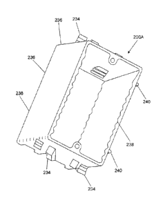
For example, in the embodiment shown in FIG. 7A, the mountable junction box
200A can
include one or more brackets or a set of nail guides 234 mounted to one or
more side walls or
end walls of the junction box 200A. In addition, the mountable junction box
200A can
include one or more stiffeners, contoured shapes, or patterns 236, 238 formed
in certain
portions of a junction box to facilitate maintaining a rectangular-shape or
other desired shape
of the opening, such as 120. Furthermore, one or more stud markers 240 or stud
guides can
be positioned at certain portions of a junction box, such as on the side walls
and adjacent to
the corners of the box, to minimize deflection of the junction box when the
box is mounted to
a wall stud and/or to orient the junction box with respect to a face of a wall
stud or wall. In
certain embodiments, the one or more stud guides can be operable to maintain a
predefined
distance between a frame face and a face of an adjacent stud or wall and the
frame during
installation of the electrical accessory
In the embodiment shown in FIG. 7B, the side walls 286 of the mountable
junction box 200J
are in parallel relation with each other, and likewise, the end walls are also
in parallel relation
with each other, wherein a frame face 287 is defined by upper edges of the two
side walls and
the two end walls. A lower wall or fifth wall of the junction box 200J is
disposed between
13
05015052-70CA
CA 02714372 2010-09-02
the two side walls and two end walls. The mountable junction box 200J can
include one or
more brackets or a set of nail guides 282 mounted to one or more side walls
286 or end walls
of the junction box 200J. As shown in FIG. 7B, the nail guides 282 can include
a plurality of
guide portions, such as one or more upper and lower guide portions 282A, 282B
mounted to
end walls of the junction box 200J. In the embodiment shown in FIG. 7B, the
guide portions,
such as 282A and 282B, adjacent to the corners of the junction box 200J can
extend slightly
beyond the side walls to provide additional mounting support to adjacent wall
studs when the
nail guides 282 are mounted to a wall stud and nails or fasteners are driven
through the nail
guides 282. That is, when the junction box 200J is positioned against an
adjacent wall stud
during installation of the junction box 200J, the nail guide 282, particularly
lower guide
portions 282A and upper guide portions 282B, are positioned immediately
adjacent to the
wall stud 200J. Lower guide portions 282A and upper guide portions 282B can be
configured to receive or otherwise contact a portion of a nail or other type
of fastener. For
example, each of the guide portions 282A and 282B can include a slot or groove
shaped to
receive an axial portion of nail. Furthermore, each of the guide portions
282A, 282B can be
positioned in opposing configurations to contact a different portion of the
nail and/or fastener.
For instance, a lower guide portion 282A can be positioned to receive or
contact a lower axial
portion of a nail, and an upper guide portion 282B can be positioned to
receive or contact an
upper axial portion of a nail. In this manner, the nail guides such as 282 can
absorb some or
all of the force applied to the nail guides 282 and junction box 200J during
installation when
nails or fasteners are driven through the nail guides 282 as the junction box
200J is mounted
to an adjacent wall stud. Avoiding some or all of such force can minimize or
prevent flexing
of the junction box 200J during installation. This may help the junction box
200J maintain its
general or approximate rectangular shape during installation. That is, the
nail guides 282 can
be operable to maintain the approximate shape of the junction box 200J during
installation.
In addition, the mountable junction box 200J can include one or more brackets
or stud guides
284 mounted to one or more side walls or end walls of the junction box 200J.
As shown in
FIG. 7B, the stud guides 284 can be shaped as relatively short protrusions
mounted to the side
walls and adjacent to the corners of the junction box 200J. For example, a
stud guide such as
284 can be positioned at a junction between at least one side wall such as 286
and at least one
end wall. In the embodiment shown in FIG. 7B, the stud guides 284 can extend
slightly
beyond the side walls 286, e.g., perpendicularly to the side walls 286, to
provide additional
14
05015052-70CA
CA 02714372 2010-09-02
positioning guidance to adjacent wall studs when the junction box 200J is
mounted to an
adjacent wall stud. That is, when the junction box 200J is positioned against
an adjacent wall
stud during installation of the junction box 200J, the stud guide 284, can be
positioned
immediately adjacent to a face of the wall stud 200J or wall. Thus, each stud
guide 284 can
maintain a predefined distance between a frame face, such as 287, and a face
of an adjacent
wall stud or wall and the junction box 200J during installation of the box
200J. In this
manner, the stud guides 284 can help a user position the junction box 200J
with respect to a
wall stud or wall and/or the stud guides 284 may absorb some or all of the
force applied to
the stud guide 284 and junction box 200J, particularly during installation
when nails or
fasteners are driven through the nail guides 282 as the junction box 200J is
mounted to an
adjacent wall stud. In certain instances, avoiding some or all of such force
can minimize or
prevent flexing of the junction box 200J during installation. This may also
help the junction
box 200J maintain its general or approximate rectangular shape during
installation.
Furthermore, the mountable junction box 200J can include an increased side
wall width or
bridge 286 to increase the strength and rigidity of the junction box 200J. The
increased side
wall width or bridge 286 can be along a length of at least one side wall, such
as the width of
an upper portion of the side wall, wherein the bridge 286 is operable to
provide added
material thickness to a portion of the at least one side wall. For example,
the bridge 286 or
width of an upper portion of the side wall, particularly between the stud
guides 284 adjacent
the corners of the junction box 200J, can be increased in material thickness.
The approximate
height of the increased thickness of the bridge 286 or upper portion of the
side wall can be
approximately 0.040 inches across the width of the side wall between the stud
guides 284.
This may help the junction box 200J maintain its general or approximate
rectangular shape
during installation.
Furthermore, in certain embodiments, one or more stud markers 240 or stud
guides can be
positioned at certain portions of a junction box, such as on the side walls
and adjacent to the
corners of the box, to minimize deflection of the junction box when the box is
mounted to a
wall stud. This may also help the junction box 200J maintain its general or
approximate
rectangular shape during installation.
Moreover, the mountable junction box 200J can include an increased internal
box volume
over conventional junction boxes. In the embodiment shown in FIG. 7B, the
mountable
05015052-70CA
CA 02714372 2010-09-02
junction box 200J can include at least one radiused corner between at least
one end wall and
the lower wall. For example, adjacent to the end walls, the lower end walls
can include
radiused corners 288, which in turn, can increase the overall internal box
volume 290
bounded by the end walls, side walls, front opening, and rear wall of the
junction box 200J.
In this manner, the internal box volume 290 can accommodate additional
electrical
components or otherwise facilitate easier consumer or user installation of
electrical
components within the box 200J. This may also help the junction box 200J
maintain its
general or approximate rectangular shape during installation.
In the embodiment shown in FIGs. 8 - 10, a mountable junction box 200B can
include one or
more brackets or a set of angled nail guides 242. As shown, the nail guides
242 can be
mounted to the side walls of the junction box 200B, and can receive nails or
other mounting
devices to mount the junction box 200B to a face of a wall stud, such as 244.
An optional
face plate 246, shown in FIGs. 9 and 10, can be mounted to the junction box
200B to cover
an associated opening of the junction box 200B.
In the embodiments shown in FIGs. 11 - 16, a mountable junction box, such as
200C, 200D,
200E, 200F, 200G, 200H, 2001, 200J, 200K, 200L, 200M, 200N, can include one or
more
brackets or a set of angled nail guides 248. As shown in FIG. 11, the
mountable junction box
200C can include a connecting device, such as a pin 250, to mount to and
connect two
junction boxes 200C, 200D together. Corresponding slots 252 in the side walls
of the
junction boxes 200C, 200D can facilitate insertion of the connecting device or
pin 250 into
the slot, wherein the junction boxes 200C, 200D can be mounted adjacent to
each other when
one junction box, such as 200C, is mounted to a wall stud, such as 254. Other
embodiments
can use any number of as well as different shapes, configurations, and
locations of connecting
devices, pins, and slots to mount two adjacent mountable junction boxes
together.
In another embodiment, such as in FIG. 12, a connecting device for a mountable
junction
box, such as 200E, can be a dovetail-shaped element, such as 256, which can be
mounted to
or otherwise formed in the side wall of the junction box 200E. A corresponding
dovetail-
shaped slot, such as 258, can be formed or otherwise machined in the side wall
of another
junction box, such as 200F, wherein the dovetail element 256 can be mounted
within the slot
258 to mount the junction boxes 200E, 200F adjacent to each other when one
junction box,
such as 200E, is mounted to a wall stud, such as 254. Other embodiments can
use any
16
05015052-70CA
CA 02714372 2010-09-02
number of as well as different shapes, configurations, and locations of
elements, dovetail-
shaped elements, slots, and dovetail-shaped slots to mount two adjacent
mountable junction
boxes together.
In another embodiment, such as in FIG. 13, a connecting device for a mountable
junction
box, such as 200G, can be a locking pin, such as 260, which can be mounted to
or otherwise
screwed into a corresponding hole, such as 262, in the side wall of the
junction box 200G. A
corresponding shaped nut or receiving hole, such as 264, can be formed in or
otherwise
mounted to the side wall of another junction box, such as 200H, wherein the
locking pin 260
can be mounted within the holes 262, 264 to mount the junction boxes 200G,
200H adjacent
to each other when one junction box, such as 200H, is mounted to a wall stud,
such as 254.
Other embodiments can use any number of as well as different shapes,
configurations, and
locations of locking pins, holes, and shaped nuts to mount two adjacent
mountable junction
boxes together.
In another embodiment, such as in FIG. 14, a connecting device for a mountable
junction
box, such as 2001, can be a snap button, such as 266, which can be mounted to
or otherwise
formed on the side wall of the junction box 2001. A corresponding shaped
receiving hole,
such as 268, can be formed in or otherwise machined in the side wall of
another junction box,
such as 200J, wherein the snap button 266 can be mounted within the hole 268
to mount the
junction boxes 2001, 200J adjacent to each other when one junction box, such
as 2001, is
mounted to a wall stud, such as 254. Other embodiments can use any number of
as well as
different shapes, configurations, and locations of snap buttons and holes to
mount two
adjacent mountable junction boxes together.
In another embodiment, such as in FIG. 15, a connecting device for a mountable
junction
box, such as 200K, can be a male-type protrusion or tongue, such as 270, which
can be
mounted to or otherwise formed in the side wall of and adjacent to the upper
wall and/or
lower wall of the junction box 200K. A corresponding female-type track or
groove, such as
272, can be formed in or otherwise mounted to the side wall of and adjacent to
the upper wall
and/or lower wall of another junction box, such as 200L, wherein the male-type
protrusion or
tongue 270 can be mounted within the female-type track or groove 272 to mount
the junction
boxes 200K, 200L adjacent to each other when one junction box, such as 200L,
is mounted to
a wall stud, such as 254. Other embodiments can use any number of as well as
different
17
05015052-70CA
CA 02714372 2010-09-02
shapes, configurations, and locations of male-type protrusions, tongues,
female-type tracks,
and grooves to mount two adjacent mountable junction boxes together.
In another embodiment, such as in FIG. 16, a connecting device can be a male-
type
protrusion or tongue, such as 274, which can be mounted to or otherwise formed
in the side
wall of and adjacent to the upper wall and/or lower wall of a junction box,
such as 200M. A
corresponding female-type track or groove, such as 276, can be formed in or
otherwise
mounted to the side wall of and adjacent to the upper wall and/or lower wall
of another
junction box, such as 200N, wherein the male-type protrusion or tongue 274 can
be mounted
within the female-type track or groove 276 to mount the junction boxes 200M,
200N adjacent
to each other when one junction box, such as 200N, is mounted to a wall stud,
such as 254.
An end cap 278 can be mounted to an open side of a junction box, such as 200M,
via a
tongue-and-groove type connector arrangement, wherein the end cap 278 includes
a female-
type track or groove 280 that can cooperate with and mount to a male-type
protrusion or
tongue, such as 274, associated with the junction box 200M. Other embodiments
can use any
number of as well as different shapes, configurations, and locations of male-
type protrusions,
tongues, female-type tracks, and grooves to mount two adjacent mountable
junction boxes
together.
Other embodiments and features of example mountable electrical junction boxes
and/or
accessories are described in FIGs. 22 - 40 below.
FIG. 17 is a perspective view of example stackable electrical junction boxes
in accordance
with an embodiment of the invention. A pair of identical electrical junction
boxes 300A,
300B are shown in FIG. 17 in a stackable, aligned orientation. In the
embodiment shown in
FIG. 17, the electrical junction box 300A can include a rectangular-shaped
housing that
includes a pair of side walls 302, 304, an upper wall 306, a lower wall 308,
and a rear wall
310. In certain embodiments, such as 300A in FIG. 17, one or more cable
openings, clamps,
punch outs, and mounting holes can be included. An opening 320 in the front
portion of the
junction box 300 is sized to receive an electrical component, such as a switch
or outlet, which
can be mounted within the junction box 300A via one or more screws secured
within the
mounting holes. Furthermore, the junction box 300 shown in FIG. 17 can include
a stacking
tab 322 mounted to an exterior surface of one side wall and a corresponding
stacking notch
324 in an opposing side wall. In the embodiment shown, the stacking tab 322
can be a
18
05015052-70CA
CA 02714372 2010-09-02
rectangular-shaped block, and the corresponding stacking notch 324 can be
rectangular-
shaped channel or groove. In other embodiments, a stacking tab and
corresponding stacking
notch can have other designs, shapes, and configurations, such as a tongue and
groove
configuration. In other embodiments, a series of tabs and notches can be used.
When at least two junction boxes, such as 300A and 300B, are rotated about 180
degrees
from each other, wherein the junction boxes are facing opposing directions,
the junction
boxes 300A, 300B can be stacked together as shown in FIG. 17. As shown, the
stacking tab
322 of one junction box 300A can fit within the corresponding stacking notch
324 of the
other junction box 300B. Other similarly shaped junction boxes similar to 300A
and 300B
can be stacked with the pair of stacked boxes 300A, 300B when the similarly
shaped junction
boxes are rotated about 180 degrees with respect to the adjacent stacked box
300A, 300B. In
certain embodiments, a pair of junction boxes can be rotated at various angles
between 0 and
180 degrees, such as 90 degrees with respect to each other, such that a
stacking tab, similar to
322, cooperates with a stacking notch, such as 324, to facilitate nesting and
stacking of one
junction box within another junction box. In any instance, when the junction
boxes 300A,
300B are similarly oriented, i.e., when the pair of junction boxes are not
rotated with respect
to each other, such as 0 degrees with respect to each other, the stacking tab
322 of at least one
junction box, such as 300A, interferes with a notchless wall of the other
junction box, such as
300B, thus preventing or otherwise inhibiting the stacking of the junction
boxes 300A, 300B
together. In this manner, in accordance with certain embodiments of the
invention, multiple
junction boxes can be transported and/or stored together while minimizing the
space required
by each respective unstacked junction box, and thereby can reduce the burden
of carrying
and/or storing multiple junction boxes together.
The junction boxes 300A, 300B shown in FIG. 17 is shown by way of example
only, and
other configurations, shapes, and designs can exist in accordance with other
embodiments of
the invention.
FIG. 18 is a series of views of example stackable electrical junction boxes in
accordance with
an embodiment of the invention. In the detail view shown in FIG. 18, a
stacking tab 326 of
one junction box 300C can fit within the corresponding stacking notch 328 of
the other
junction box 300D. In this manner, when the junction boxes 300C is rotated
about 180
degrees with respect to the adjacent junction box 300D, a portion of the
junction box 300C
19
05015052-70CA
CA 02714372 2010-09-02
can be nested within a portion of the junction box 300D, thus facilitating
stacking of the
junction boxes 300C, 300D. When the junction boxes 300C, 300D are similarly
oriented,
interference between the stacking tab 326 of at least one junction box, such
as 300C, and a
notchless wall of the other junction box, such as 300D, can prevent or
otherwise inhibit the
stacking of the similarly oriented junction boxes 3000, 300D together.
FIGs. 19 - 21 illustrate various example methods of manufacturing and/or using
the junction
boxes and/or accessories, such as 100, 200, 300 illustrated above. Each of the
flowcharts
400, 500, 600 shown in FIGs. 19, 20, and 21, respectively, are shown by way of
example
only, and can have fewer or greater numbers of elements than shown.
In FIG. 19, a example method for manufacturing an electrical junction box or
electrical
accessory is shown. The method 400 begins at block 402. In block 402, at least
one flexible
material operable to form an electrical junction box is provided.
Block 402 is followed by block 404, in which the at least one flexible
material is molded to
form an electrical junction box or electrical accessory comprising a pair of
side walls, an
upper wall, a lower wall, and a rear wall, wherein an opening is formed
between the pair of
side walls, an upper wall, and a lower wall.
Example electrical junction boxes or electrical accessories created by an
embodiment of the
method 400 shown in FIG. 19 are illustrated in FIGs. 1 - 5.
The method 400 ends at block 404.
In FIG. 20, another example method for manufacturing an electrical junction
box or electrical
accessory is shown. The method 500 begins at block 502. In block 502, at least
one
electrical junction box comprising a pair of side walls, an upper wall, a
lower wall, and a rear
wall is provided, wherein an opening is formed between the pair of side walls,
an upper wall,
and a lower wall.
Block 502 is followed by block 504, in which a mounting bracket is mounted on
an end wall
of the electrical junction box, wherein the mounting bracket is operable to
mount the box to a
front face of a wall stud.
05015052-70CA
CA 02714372 2010-09-02
Block 504 is followed by block 506, in which a second mounting bracket is
mounted to the
end wall of the electrical junction box, wherein the second mounting bracket
is operable to
mount the box to a lateral face of a wall stud.
Example electrical junction boxes created by an embodiment of the method 500
shown in
FIG. 20 are illustrated in FIGs. 6A, 6B, 7A, 7B, and 8 - 16.
The method 500 ends at block 506.
In FIG. 21, another example method for manufacturing an electrical junction
box or electrical
accessory is shown. The method 600 begins at block 602. In block 602, at least
one
electrical junction box comprising a pair of side walls, an upper wall, a
lower wall, and a rear
wall is provided, wherein an opening is formed between the pair of side walls,
an upper wall,
and a lower wall.
Block 602 is followed by block 604, in which a stacking tab on an exterior
portion of the
junction box is provided.
Block 604 is followed by block 606, in which a corresponding stacking notch on
the exterior
portion of the junction box is provided, wherein a second junction box with a
stacking tab can
mount partially within the junction box when the second junction box is
rotated more than
about 0 degrees with respect to the other junction box.
Example electrical junction boxes or electrical accessories created by an
embodiment of the
method 600 shown in FIG. 21 are illustrated in FIGs. 17 - 18.
The method 600 ends at block 606.
In the embodiment shown in FIG. 22, an embodiment of an electrical accessory
700 is
illustrated. The electrical accessory 700 shown can include at least one
locating and
positioning arm 702 mounted to a molded frame 704, which can be mounted to one
or more
corners of an existing or adjacent junction box or electrical accessory for
low voltage use.
This embodiment can incorporate a locating and positioning arm 702 extending
from the
upper and lower surfaces or end walls 706, 708 of the frame. When the locating
and
positioning arm 702 is fitted over the corners of an existing or adjacent
junction box or
21
05015052-70CA
CA 02714372 2010-09-02
electrical accessory, the existing or adjacent junction box or electrical
accessory can be held
relative to the molded frame 704.
As shown in FIG. 22, the upper end wall 706 and lower end wall 708 are
disposed in
substantially parallel relation to each other. A pair of side walls 710, 712
disposed in
substantially parallel relation to each other, are each further disposed
between the two end
walls. The locating and positioning arms 702 are shown mounted to at least one
of the end
walls, such as 706 and 708. Each of the locating and positioning arms 702
includes a support
leg 714 mounted to the corresponding end wall 706, 708, and a respective prong
716
substantially perpendicular to the corresponding locating and positioning arm
702. In this
manner, a side wall portion of an adjacent junction box or electrical
accessory can be
positioned between the prongs 716 and side wall 712 of the electrical
accessory 700. In
certain other embodiments, the locating and positioning arms and associated
prongs can be
smaller or larger, and may have different dimensions or shapes.
In one embodiment, a support leg of the locating and positioning arms can
include an initial
portion operable to mount to at least one of the end walls, an angled portion
which extends
outward from the initial portion and the frame, and an extension from the
angled portion
which overhangs an adjacent region for mounting the adjacent electrical
accessory between at
least one prong and at least one side wall.
In the embodiment shown in FIG. 22, at least one stop tab such as 718 can be
mounted to the
locating and positioning arms 702. As shown in FIG. 22, each stop tab can be a
slightly
curved or arcuate piece of material extending from each locating and
positioning arms 702.
The curvature of the stop tab can be operable to accommodate the corresponding
exterior
shape of an adjacent junction box or electrical accessory to be positioned
adjacent to the
electrical accessory 700 or frame 704. Each of the stop tabs 718 shown can be
operable to
contact an adjacent junction box or electrical accessory when the adjacent
junction box or
electrical accessory is positioned between the prongs 716 and the side wall
712 of the
electrical accessory 700. In certain other embodiments, the stop tabs can be
smaller or larger,
and may have different dimensions or shapes.
For instance, in at least one embodiment, at least one stop tab can be mounted
to at least one
side wall or one end wall of the frame or electrical accessory. For example,
instead of a stop
22
05015052-70CA
CA 02714372 2010-09-02
tab mounted to the locating and positioning arm such as 702, one or more stop
tabs can be
mounted to the side wall, such as 712, or one end wall of the frame, such as
704, or electrical
accessory, such as 700. In any instance, each stop tab is operable to contact
an adjacent
electrical accessory when the adjacent electrical accessory is positioned
between the prongs
716 and side wall 712 of the electrical accessory 700.
The junction box and/or electrical accessory 700 shown in FIG. 22 is shown by
way of
example only, and other configurations, shapes, and designs can exist in
accordance with
other embodiments of the invention.
In the embodiments shown in FIGs. 23 - 26, an example electrical accessory 800
is
illustrated. The electrical accessory 800 shown can include at least one
locating and
positioning arm 802 mounted to a molded frame 804, which can be mounted to one
or more
corners of an existing or adjacent junction box or electrical accessory for
low voltage use.
For instance, FIG. 26 is a side perspective view of the mountable electrical
accessory shown
in FIG. 24 with a junction box 805 mounted adjacent to the electrical
accessory 800 in
accordance with an embodiment of the invention. This embodiment, as shown in
FIGs. 23,
can incorporate a locating and positioning arm 802 extending from the upper
and lower
surfaces or end walls 806, 808 of the frame. When the locating and positioning
arm 802 is
fitted over the corners of an existing or adjacent junction box or electrical
accessory, the
existing or adjacent junction box or electrical accessory can be held relative
to the molded
frame 804. In certain other embodiments, the locating and positioning arms and
associated
prongs can be smaller or larger, and may have different dimensions or shapes.
As shown in FIGs. 23 - 25, the upper end wall 806 and lower end wall 808 are
disposed in
substantially parallel relation to each other. A pair of side walls 810, 812
disposed in
substantially parallel relation to each other, are each further disposed
between the two end
walls. The locating and positioning arms 802 are shown mounted to at least one
of the end
walls, such as 806 and 808. Each of the locating and positioning arms 802
includes a support
leg 814 mounted to the corresponding end wall 806, 808, and a respective prong
816
substantially perpendicular to the corresponding locating and positioning arm
802. In this
manner, a side wall portion of an adjacent junction box or electrical
accessory can be
positioned between the prongs 816 and side wall 812 of the electrical
accessory 800.
23
05015052-70CA
CA 02714372 2010-09-02
In one embodiment, a support leg of the locating and positioning arms can
include an initial
portion operable to mount to at least one of the end walls, an angled portion
which extends
outward from the initial portion and the frame, and an extension from the
angled portion
which overhangs an adjacent region for mounting the adjacent electrical
accessory between at
least one prong and at least one side wall.
In the embodiments shown in FIGs. 23 - 25, at least one stop tab such as 818
can be mounted
to the side wall and/or end wall of the electrical accessory 800 away from the
locating and
positioning arm 802. As shown in FIGs. 23 and 24, each stop tab can be a
relatively small
piece of material extending from the side wall and/or end wall. The stop tab
can be operable
to contact the exterior of an adjacent junction box or electrical accessory to
be positioned
adjacent to the electrical accessory 800 or frame 804, or in some instances,
can be shaped to
accommodate the corresponding exterior shape of an adjacent junction box or
electrical
accessory to be positioned adjacent to the electrical accessory 800 or frame
804. Each of the
stop tabs 818 shown can be operable to contact an adjacent junction box or
electrical
accessory when the adjacent junction box or electrical accessory is positioned
between the
prongs 816 and the side wall 812 of the electrical accessory 800. In certain
other
embodiments, the stop tabs can be smaller or larger, and may have different
dimensions or
shapes.
In at least one embodiment, such as in FIG. 23, at least one notch such as
820A, 820B in at
least one of the side walls can be operable to accommodate an adjacent
junction box or
electrical accessory when the adjacent junction box or electrical accessory is
positioned
between the prongs 816 and the side wall 812 of the electrical accessory 800.
For example,
the at least one notch 820A, 820B can be adjacent to the prongs 816 of the
electrical
accessory 800, wherein the at least one notch can accommodate the upper
portion of the side
wall of the adjacent junction box or electrical accessory. In certain other
embodiments, the
notch can be smaller or larger, and may have different dimensions or shapes.
The junction boxes and/or electrical accessories 800 shown in FIGs. 23 - 26
are shown by
way of example only, and other configurations, shapes, and designs can exist
in accordance
with other embodiments of the invention.
24
05015052-70CA
CA 02714372 2010-09-02
In the embodiment shown in FIG. 27, another embodiment of an electrical
accessory 900 is
illustrated. The electrical accessory 900 shown can include at least one
locating and
positioning arm 902 mounted to a molded frame 904, which can be mounted to one
or more
corners of an existing or adjacent junction box or electrical accessory for
low voltage use.
This embodiment can incorporate a locating and positioning arm 902 extending
from the
upper and lower surfaces or end walls 906, 908 of the frame. When the locating
and
positioning arm 902 is fitted over the corners of an existing or adjacent
junction box or
electrical accessory, the existing or adjacent junction box or electrical
accessory can be held
relative to the molded frame 904.
As shown in FIG. 27, the upper end wall 906 and lower end wall 908 are
disposed in
substantially parallel relation to each other. A pair of side walls 910, 912
disposed in
substantially parallel relation to each other, are each further disposed
between the two end
walls. The locating and positioning arms 902 are shown mounted to at least one
of the end
walls, such as 906 and 908. Each of the locating and positioning arms 902
includes a support
leg 914 mounted to the corresponding end wall 906, 908, and a respective prong
916
substantially perpendicular to the corresponding locating and positioning arm
902. In this
manner, a side wall portion of an adjacent junction box or electrical
accessory can be
positioned between the prongs 916 and side wall 912 of the electrical
accessory 900. In
certain other embodiments, the locating and positioning arms and associated
prongs can be
smaller or larger, and may have different dimensions or shapes.
In one embodiment, a support leg of the locating and positioning arms can
include an initial
portion operable to mount to at least one of the end walls, an angled portion
which extends
outward from the initial portion and the frame, and an extension from the
angled portion
which overhangs an adjacent region for mounting the adjacent electrical
accessory between at
least one prong and at least one side wall.
In the embodiment shown in FIG. 27, at least one stop tab such as 918 can be
mounted to the
side wall and/or end wall of the electrical accessory 900 away from but in
close proximity to
the locating and positioning arm 902. As shown in FIG. 27, the stop tab can be
a relatively
small piece of material extending from the side wall and/or end wall. The stop
tab can be
operable to contact the exterior of an adjacent junction box or electrical
accessory to be
positioned adjacent to the electrical accessory 900 or frame 904, or in some
instances, can be
05015052-70CA
CA 02714372 2010-09-02
shaped to accommodate the corresponding exterior shape of an adjacent junction
box or
electrical accessory to be positioned adjacent to the electrical accessory 900
or frame 904.
The stop tab 918 shown can be operable to contact an adjacent junction box or
electrical
accessory when the adjacent junction box or electrical accessory is positioned
between the
prongs 916 and the side wall 912 of the electrical accessory 900. In certain
other
embodiments, the stop tab can be smaller or larger, and may have different
dimensions or
shapes.
In at least one embodiment, at least one notch in at least one of the side
walls can be operable
to accommodate an adjacent junction box or electrical accessory when the
adjacent junction
box or electrical accessory is positioned between the prongs 916 and the side
wall 912 of the
electrical accessory 900.
The junction box and/or electrical accessory 900 shown in FIG. 27 is shown by
way of
example only, and other configurations, shapes, and designs can exist in
accordance with
other embodiments of the invention.
In the embodiment shown in FIG. 28, another embodiment of an electrical
accessory 1000 is
illustrated. The electrical accessory 1000 shown can include at least one
locating and
positioning arm 1002 mounted to a molded frame 1004, which can be mounted to
one or
more corners of an existing or adjacent junction box or electrical accessory
for low voltage
use. This embodiment can incorporate a locating and positioning arm 1002
extending from
the upper and lower surfaces or end walls 1006, 1008 of the frame. When the
locating and
positioning arm 1002 is fitted over the corners of an existing or adjacent
junction box or
electrical accessory, the existing or adjacent junction box or electrical
accessory can be held
relative to the molded frame 1004.
As shown in FIG. 28, the upper end wall 1006 and lower end wall 1008 are
disposed in
substantially parallel relation to each other. A pair of side walls 1010, 1012
disposed in
substantially parallel relation to each other, are each further disposed
between the two end
walls. The locating and positioning arms 1002 are shown mounted to at least
one of the end
walls, such as 1006 and 1008. Each of the locating and positioning arms 1002
includes a
support leg 1014 mounted to the corresponding end wall 1006, 1008, and a
respective prong
1016 substantially perpendicular to the corresponding locating and positioning
arm 1002. In
26
05015052-70CA
CA 02714372 2010-09-02
this manner, a side wall portion of an adjacent junction box or electrical
accessory can be
positioned between the prongs 1016 and side wall 1012 of the electrical
accessory 1000. In
certain other embodiments, the locating and positioning arms and associated
prongs can be
smaller or larger, and may have different dimensions or shapes.
In the embodiment shown in FIG. 28, at least one stop tab such as 1018 can be
mounted to a
lower portion of at least one of the locating and positioning arms 1002 away
from but in close
proximity to the side wall and/or end wall. As shown in FIG. 28, the stop tab
can be a
relatively small piece of material extending from the locating and positioning
arm 1002. The
stop tab can be operable to contact the exterior of an adjacent junction box
or electrical
accessory to be positioned adjacent to the electrical accessory 1000 or frame
1004, or in some
instances, can be shaped to accommodate the corresponding exterior shape of an
adjacent
junction box or electrical accessory to be positioned adjacent to the
electrical accessory 1000
or frame 1004. The stop tab 1018 shown can be operable to contact an adjacent
junction box
or electrical accessory when the adjacent junction box or electrical accessory
is positioned
between the prongs 1016 and the side wall 1012 of the electrical accessory
1000. In certain
other embodiments, the stop tab can be smaller or larger, and may have
different dimensions
or shapes.
In at least one embodiment, at least one notch in at least one of the side
walls can be operable
to accommodate an adjacent junction box or electrical accessory when the
adjacent junction
box or electrical accessory is positioned between the prongs 1016 and the side
wall 1012 of
the electrical accessory 1000.
The junction box and/or electrical accessory 1000 shown in FIG. 28 is shown by
way of
example only, and other configurations, shapes, and designs can exist in
accordance with
other embodiments of the invention.
FIGs. 29A and 29B illustrate an example hinge for a mountable junction box
and/or electrical
accessory in accordance with an embodiment of the invention. In the embodiment
shown in
FIG. 29A, at least one side wall flap 1100 is operable to fold adjacent to at
least one side wall
1102 of the junction box 1104 and/or electrical accessory. The side wall flap
is further
operable to mount the junction box 1104 and/or electrical accessory to an
adjacent wall or
wall stud. As shown in FIG. 29A, one or more mounting holes 1106 can be
provided in the
27
05015052-70CA
CA 02714372 2010-09-02
side wall flap 1100 to facilitate mounting the junction box 1104 and/or
electrical accessory to
an adjacent wall or wall stud. A living hinge 1108 positioned between the side
wall flap 1100
and the side wall of the junction box 1104 permits the side wall flap 1100 to
fold adjacent to
and substantially against the side wall 1102. The living hinge permits the
side wall flap 1100
to be maintained as an integral portion of the junction box 1104 and/or
electrical accessory.
In one example, the living hinge can be a relatively flexible portion of
material disposed
between the side wall flap 1100 and the side wall of the junction box 1104. In
another
example, a living hinge may be a mechanical type device disposed between the
side wall flap
1100 and the side wall of the junction box 1104.
As shown in FIG. 29B, at least one latch 1110 is operable to maintain the side
wall flap 1100
in a folded position adjacent to and substantially against the side wall 1102
of the junction
box 1104 and/or electrical accessory. The latch 1110 shown in FIG. 29B can be
a relatively
small portion of material with a detent 1112 operable to permit a portion of
the side wall flap
1100, such as an edge, to snap relatively snug against the latch 1110 and
maintain the
position of the side wall flap 1100 in a folded position adjacent to and
substantially against
the side wall 1102. In other embodiments, one or more latches can be spaced
apart along the
side wall 1102.
The living hinge shown in FIGs. 29A and 29B is shown by way of example only,
and other
configurations, shapes, and designs can exist in accordance with other
embodiments of the
invention.
FIGs. 30 - 31 are overhead views of example concentric punch outs for a
mountable junction
box and/or electrical accessory in accordance with an embodiment of the
invention. As
shown in FIGs. 30 - 31, one or more series of concentrically aligned punch
outs 1200, 1202
can be molded or otherwise machined into a side wall of a mountable junction
box 1204
and/or electrical accessory. In this embodiment, each series of punch outs
1200, 1202 can
include at least three punch outs 1206, 1208, 1210, which are evenly spaced or
aligned from
each other. Between each punch out 1206, 1208, 1210 or the wall of the
junction box 1204, a
respective circumferential groove 1212, 1214, 1216 can separate the punchouts
1206, 1208,
1210, and each circumferential groove 1212, 1214, 1216 outlines the respective
punch out
1206, 1208, 1210. In the embodiments shown in FIGs. 30 - 31, each groove 1212,
1214,
1216 is approximately the same depth.
28
05015052-70CA
CA 02714372 2010-09-02
A series of depressions 1218, 1220, 1222, evenly spaced apart from each other,
can be
molded or otherwise machined in each of the punch outs 1206, 1208, 1210. Each
of the
depressions 1218, 1220, 1222 can accommodate a tip of a screwdriver or other
relatively
sharp edged object to facilitate receiving a force to knock out or otherwise
remove the
corresponding punchout.
In this manner, a mountable junction box and/or electrical accessory can be
modified as
needed to accommodate different sized cable or electrical wire runs or other
junction box
and/or electrical accessory features. The alignment and depths of the grooves,
punch outs,
and depressions can be adjusted as needed from the relative dimensions and
orientations
shown in FIG. 30 to facilitate the removal of the punch outs.
The punch outs shown in FIGs. 30 - 31 are shown by way of example only, and
other
configurations, shapes, and designs can exist in accordance with other
embodiments of the
invention.
FIGs. 32 - 35 are views of another example mountable junction box and/or
electrical
accessory in accordance with an embodiment of the invention. In the embodiment
shown in
FIGs. 32 - 35, an electrical junction box 1300 can include a rectangular-
shaped housing that
includes a pair of side walls 1302, 1304, an upper wall 1306, a lower wall
1308, and a rear
wall 1310. In the embodiment shown, such as 1300 in FIGs. 32 - 35, one or more
cable
openings 1312, clamps 1314, punch outs 1316, and mounting holes 1318 can be
included. A
pair of receptacle mount openings or holes 1320 in the front portion of the
junction box 1300
and/or electrical accessory is sized to receive an electrical component, such
as a switch or
outlet, which can be mounted within the junction box 1300 and/or electrical
accessory via
one or more screws or fasteners secured within the receptacle mount openings
or holes 1320.
Furthermore, the junction box 1300 and/or electrical accessory shown in FIGs.
32 - 35 can
include a series of coverplate mounting holes 1322 positioned at the opposing
end walls
1306, 1308, of the junction box 1300 and/or electrical accessory to receive
corresponding
coverplate mounting screws or fasteners. In the embodiment shown in FIGs. 32 -
35, the
coverplate mounting holes 1322 are intended to be slotless or otherwise
substantially covered
to protect and shield the coverplate mounting screws or fasteners. In this
manner, the
coverplate mounting holes 1322 can protect the mounting screws or fasteners
from contacting
29
05015052-70CA
CA 02714372 2010-09-02
any exposed electrical wiring within or extending from, or adjacent to the
junction box 1300
and/or electrical accessory.
In addition, as shown in FIGs. 32 - 35, a cylindrically-shaped shield 1324 can
extend from
the lower portion of each of the receptacle mount openings or holes 1320. Each
of the
cylindrically-shaped shields 1324 can substantially cover a corresponding
mounting screw or
fastener which is threaded into or otherwise inserted into the receptacle
mount openings or
holes 1320. In this manner, the cylindrically-shaped shields 1324 can protect
the mounting
screws or fasteners from contacting any exposed electrical wiring within the
junction box
1300 and/or electrical accessory.
In one embodiment, and as shown in FIG. 35, a horizontally-oriented groove
1326 or
depression can be molded or otherwise machined into a portion of each
cylindrically-shaped
shields 1324. The grooves 1326 can facilitate removal of the cylindrically-
shaped shields
1324 should an adjacent punch out 1316 on the respective end walls 1306, 1308
be removed.
Since the punch outs 1316 and cylindrically-shaped shields 1324 are not in
direct or other
substantial contact with each other, the removal of the adjacent punch out
1316 can facilitate
removal of the cylindrically-shaped shields 1324 since the grooves 1326
provide a stress
point or weakened material portion to remove the shields 1324 from the
junction box 1300
and/or electrical accessory.
In one embodiment, the punch outs, such as 1316, can be a series of
concentrically aligned
punch outs similar to the configuration shown in FIG. 30 described above. In
any instance, a
junction box such as 1300 can be configured with either concentrically aligned
punch outs
and/or non-concentrically aligned punch outs, which are illustrated as 216 in
FIGs. 6A and
6B.
The junction box 1300 and/or electrical accessory shown in FIGs. 32 - 35 is
shown by way of
example only, and other configurations, shapes, and designs can exist in
accordance with
other embodiments of the invention.
FIG. 36 is yet another example mountable junction box and/or electrical
accessory in
accordance with an embodiment of the invention. Beginning at the top of the
figure and
moving left to right, the views include an upper view, a left side view, a
detail upper view of
A from the top view, and right, overhead perspective view, a lower end view,
and a left,
05015052-70CA
CA 02714372 2010-09-02
lower side perspective view. In the embodiment shown in FIG. 36, an electrical
junction box
1400 can include a rectangular-shaped housing that includes a pair of side
walls 1402, 1404,
an upper wall 1406, a lower wall 1408, and a rear wall 1410. In the embodiment
shown, such
as 1400 in FIG. 36, one or more cable openings 1412, clamps 1414, punch outs
1416, and
mounting holes 1418 can be included. A pair of receptacle mount openings or
holes 1420 in
the front portion of the junction box 1400 and/or electrical accessory is
sized to receive an
electrical component, such as a switch or outlet, which can be mounted within
the junction
box 1400 and/or electrical accessory via one or more screws or fasteners
secured within the
receptacle mount openings or holes 1420.
Furthermore, the junction box 1400 and/or electrical accessory shown in FIG.
36 can include
a series of coverplate mounting holes 1422 positioned at the opposing end
walls 1406, 1408,
of the junction box 1400 and/or electrical accessory to receive corresponding
coverplate
mounting screws or fasteners. In the embodiment shown in FIG. 36, the
coverplate mounting
holes 1422 are intended to be slotless or otherwise substantially covered to
protect and shield
the coverplate mounting screws or fasteners. As shown in the embodiment,
protrusions 1424
including the coverplate mounting holes 1422 can extend from the end walls
1406, 1408 as
needed to accommodate the coverplate mounting screws or fasteners within the
junction box
1400 and/or electrical accessory. In this manner, the coverplate mounting
holes 1422 and
protrusions 1424 can protect the mounting screws or fasteners from contacting
any exposed
electrical wiring within or extending from, or adjacent to the junction box
1400 and/or
electrical accessory.
The junction box 1400 and/or electrical accessory shown in FIG. 36 is shown by
way of
example only, and other configurations, shapes, and designs can exist in
accordance with
other embodiments of the invention.
FIG. 37 is an arrangement of views of yet another example mountable junction
box and/or
electrical accessory in accordance with an embodiment of the invention.
Beginning at the top
of the figure and in a clockwise direction, the views include a bottom view, a
left upper
perspective view, a front view, and a left side view. In the embodiment shown
in FIG. 37, an
electrical junction box 1500 can include a rectangular-shaped housing that
includes a pair of
side walls 1502, 1504, an upper wall 1506, a lower wall 1508, and a rear wall
1510. The
junction box 1500 can also include an adjustable bracket 1512 operable for
mounting the
31
05015052-70CA
CA 02714372 2010-09-02
junction box 1500 to an adjacent wall or wall stud can be oriented
substantially adjacent to at
least one side wall, such as 1502. The bracket 1512 can include, for instance,
a pair of
protrusions 1514, 1516 or box clamp operable to engage a portion of
correspondingly shaped
grooves in the upper wall 1506 and lower wall 1508 of the junction box 1500, a
mounting
surface 1517, and, for instance, another pair of protrusions 1518, 1520 or
stud clamp operable
to engage a portion of a stud wall or stud. The pair of protrusions 1514, 1516
or box clamp
can be part of a sliding plate portion of the adjustable bracket 1512 which
can generally
conform with the exterior shape of a portion of the rectangular-shaped
housing, such as a
portion of the side wall 1502 and a portion of the upper wall 1506. In this
example, the pair
of protrusions 1514, 1516 can be generally V-shaped. The mounting surface 1517
can
generally be square L-shaped. The other pair of protrusions 1518, 1520 or stud
clamp can be
part of a mounting plate portion of the adjustable bracket 1512 which can
generally conform
with the exterior shape of a portion of a stud wall or stud. In this example,
the other pair of
protrusions 1518, 1520 can be generally square-U shaped. In addition, the
bracket can
include a mounting hole 1522 or retaining clip between the protrusions 1514,
1516 to receive
a screw or fastener 1524 operable to adjust the forward or rearward position
of the bracket
1512 with respect to the junction box 1500. When the screw or fastener 1524 is
threaded or
otherwise inserted through the mounting hole 1522 and into a junction box
mounting hole
1526 or thread boss molded or otherwise connected to the side wall of the
junction box 1500,
the tightening or loosening of the screw or fastener 1524 can rotate the screw
or fastener
1524, thus moving the bracket 1512 with the screw or fastener 1524 as it
travels with respect
to the junction box 1500.
In one embodiment, the electrical junction box 1500 can include one or more
stand-offs 1528
or pieces of material either molded or integral to a side wall such as 1502 or
integral or
molded to the bracket 1512. In any instance, the stand-offs 1528 are operable
to maintain a
predefined distance between the side wall 1502 and the adjustable bracket
1512.
In one embodiment, the adjustable bracket 1512 can include one or more stud
extensions
1530 and one or more stud extension mounting holes 1532 to facilitate mounting
the bracket
1512 to a portion of a stud wall or stud.
32
05015052-70CA
CA 02714372 2010-09-02
In this manner, an embodiment of an adjustable bracket, such as 1512, can
accommodate a
rectangular-shaped junction box or electrical accessory with greater internal
volume for
electrical devices and/or terminations.
The adjustable bracket 1512 and junction box 1500 and/or electrical accessory
shown in FIG.
37 is shown by way of example only, and other configurations, shapes, and
designs can exist
in accordance with other embodiments of the invention.
FIG. 38 is an arrangement of views of yet another example mountable junction
box and/or
electrical accessory in accordance with an embodiment of the invention.
Beginning at the top
of the figure and in a clockwise direction, the views include a top view, a
front left underside
perspective view, a bottom view, and an upper side view. A left side view is
oriented in the
center of FIG. 38. In the embodiment shown in FIG. 38, the electrical junction
box 1600
shown is similar to that shown in FIG. 37, but with a different shape
adjustable bracket 1602.
The adjustable bracket 1602 shown in FIG. 38 includes a pair of notches 1604
adjacent to a
pair of stud extensions 1606 on the lower portion of the bracket 1602. The
number, shape,
and configuration of the notches 1604 can accommodate various corresponding
shapes and
configurations of a stud wall or stud. The adjustable bracket 1602 is shown in
greater detail
in FIG. 40.
The adjustable bracket 1602 and junction box 1600 and/or electrical accessory
shown in FIG.
38 is shown by way of example only, and other configurations, shapes, and
designs can exist
in accordance with other embodiments of the invention.
FIG. 39 is an arrangement of views of yet another example mountable junction
box and/or
electrical accessory in accordance with an embodiment of the invention.
Beginning at the top
of the figure and in a clockwise direction, the views include a top view, a
front left underside
perspective view, a bottom view, and an upper side view. A left side view is
oriented in the
center of FIG. 39. In the embodiment shown in FIG. 39, an electrical junction
box 1700 can
include a rectangular-shaped housing that includes a pair of side walls 1702,
1704, an upper
wall 1706, a lower wall 1708, and a rear wall 1710. The junction box 1700 can
also include
an adjustable bracket 1712 operable for mounting the junction box 1700 to an
adjacent wall
or wall stud can be oriented substantially adjacent to at least one side wall,
such as 1702. The
bracket 1712 can include a pair of protrusions 1714, 1716 or box clamp
operable to engage a
33
05015052-70CA
CA 02714372 2010-09-02
portion of correspondingly shaped grooves in the upper wall 1706 and lower
wall 1708 of the
junction box 1700, a mounting surface 1717, and another pair of protrusions
1718, 1720 or
stud clamp operable to engage a portion of a stud wall or stud. The pair of
protrusions 1714,
1716 or box clamp can be part of a sliding plate portion of the adjustable
bracket 1712 which
can generally conform with the exterior shape of a portion of the rectangular-
shaped housing,
such as a portion of the side wall 1702 and a portion of the upper wall 1706.
The mounting
surface 1717 can generally be square L-shaped. The other pair of protrusions
1718, 1720 or
stud clamp can be part of a mounting plate portion of the adjustable bracket
1712 which can
generally conform with the exterior shape of a portion of a stud wall or stud.
In addition, the
bracket can include a housing 1721 with a mounting hole 1722 or retaining clip
between the
protrusions 1714, 1716 to receive a screw or fastener 1724 operable to adjust
the forward or
rearward position of the bracket 1712 with respect to the junction box 1700.
When the screw
or fastener 1724 is threaded or otherwise inserted through the housing 1721
and mounting
hole 1722 and into a junction box mounting hole 1726 or thread boss molded or
otherwise
connected to the side wall of the junction box 1700, the tightening or
loosening of the screw
or fastener 1724 can rotate the screw or fastener 1724, thus moving the
bracket 1712 with the
screw or fastener 1724 as it travels with respect to the junction box 1700.
In one embodiment, the electrical junction box 1700 can include one or more
stand-offs or
pieces of material either molded or integral to a side wall such as 1702 or
integral or molded
to the bracket 1712. In any instance, the stand-offs are operable to maintain
a predefined
distance between the side wall 1702 and the adjustable bracket 1712.
In one embodiment, the adjustable bracket 1702 shown in FIG. 39 includes one
or more
notches 1728 adjacent to a pair of stud extensions 1730 on the lower portion
of the bracket
1712. The number, shape, and configuration of the notches 1728 can accommodate
various
corresponding shapes and configurations of a stud wall or stud.
In one embodiment, the adjustable bracket 1712 can include one or more stud
extensions
1730 and one or more stud extension mounting holes 1732 to facilitate mounting
the bracket
1712 to a portion of a stud wall or stud.
34
05015052-70CA
CA 02714372 2010-09-02
The adjustable bracket 1712 and junction box 1700 and/or electrical accessory
shown in FIG.
39 is shown by way of example only, and other configurations, shapes, and
designs can exist
in accordance with other embodiments of the invention.
FIG. 40 illustrates a series of views of the example adjustable bracket 1602
shown in FIG. 38.
From left to right, and top to bottom, the views shown are a front edge view,
a left side view,
an upper view, an upper exploded view, and a front left lowerside perspective
view. Example
dimensions for various components of the adjustable bracket 1602 are shown in
the lower
portion of FIG. 40.
The adjustable bracket 1602 and dimensions shown in FIG. 40 is shown by way of
example
only, and other configurations, shapes, and designs can exist in accordance
with other
embodiments of the invention.
Many modifications and other embodiments of the invention will come to mind to
one skilled
in the art to which this invention pertains having the benefit of the
teachings presented in the
foregoing descriptions and the associated drawings. Therefore, it is to be
understood that the
invention is not to be limited to the specific embodiments disclosed and that
modifications
and other embodiments are intended to be included within the scope of the
appended claims.
Although specific terms are employed herein, they are used in a generic and
descriptive sense
only and not for purposes of limitation.
05015052-70CA