Note: Descriptions are shown in the official language in which they were submitted.
CA 02714507 2010-09-03
FAN BLADE IRON MOUNTING SYSTEM
REFERENCE TO RELATED APPLICATION
Applicant claims the benefit of U.S. Provisional Patent Application Serial No.
61/241,188 filed September 10, 2009.
TECHNICAL FIELD
This invention relates to ceiling fan blade irons, and specifically to systems
for
quickly connecting blade irons to a motor.
BACKGROUND OF THE INVENTION
Electrically powered ceiling fans typically have a motor mounted within a
stationary housing that is suspended from a ceiling. In operation, the motor
rotates an
annular array of individual extensions in the form of blade irons. Each blade
iron is
associated with a blade mounted thereto.
Ceiling fans are usually sold at retail with their blades packed separately
from the
blade irons for compactness, and the blade irons packed separately from the
motor. In
mounting a ceiling fan, the housing is normally mounted in suspension from the
ceiling
through a downrod and then the blades are mounted to the blade irons and the
blade irons
are mounted to the motor.
The blade irons are typically coupled to the motor by passing mounting screws
through holes in the blade iron and into threaded holes in the motor. This
task however
can be difficult or tedious when the electric motor is already suspended from
the ceiling.
The difficulty is attributed to the fact that the mounting screws are usually
passed from
the top of the blade iron to hide the screw heads from view. The installer
must align the
holes in the blade iron with the holes in the motor while simultaneously
passing the
screws through the holes. The installer typically does this from a position
below the
1
CA 02714507 2010-09-03
ceiling fan, thereby limiting the installer's ability to view the mounting
holes and thus
aligning the mounting holes and drivably rotate the screws.
Similarly, the blades of ceiling fans are usually coupled to the blade irons
by
passing mounting screws through holes in the blade and into threaded holes in
the blade
iron. Again, this task however can be difficult or tedious for the same
reasons previously
described in reference to mounting the blade irons to the motor.
Accordingly, it is seen that a need remains for a blade iron that can be
quickly and
easily mounted to a motor. It is to the provision of such therefore that the
present
invention is primarily directed.
SUMMARY OF THE INVENTION
A fan blade iron mounting system comprises fan having a motor, an annular
array
of blade iron coupled to the motor with a longitudinal axis extending
generally along the
length of the blade iron, and a blade coupled to each blade iron of the
annular array of
blade irons. Each said blade iron has a mounting portion coupled to the motor
and a body
portion removably coupled to the mounting portion. The mounting portion has a
dove
tailed tongue positioned along the longitudinal axis. The body portion has a
mounting
flange with a notch positioned along the longitudinal axis configured to
receive the
mounting portion dove tailed tongue.
BRIEF DESCRIPTION OF THE DRAWING
Figs. 1-4 are a series of perspective views of the ceiling fan blade iron
shown
being mounted to a motor embodying principles of the invention in a preferred
form.
Fig. 5 is an enlarged perspective view of a portion of the fan blade iron of
Fig. 1,
shown in an inverted position.
Fig. 6 is an enlarged perspective view of a portion of the fan blade iron of
Fig. 1,
shown in an inverted position.
DETAILED DESCRIPTION
2
CA 02714507 2010-09-03
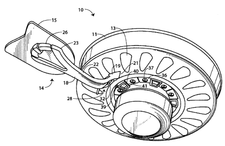
With reference next to the drawings, there is shown a ceiling fan 10 having a
motor housing 11 suspended from an unshown ceiling by an unshown downrod. An
electric motor 13 is mounted within the housing 11 and connected to a source
of electric
power by wires that extend through the downrod. The motor 13 rotatably drives
an
annular array of blade irons 14 about a motor central axis of rotation AR,
only one being
shown for clarity, each having a blade 15 mounted thereto.
Each blade iron 14 is comprised of a body portion 18 and a mounting portion
19.
The body portion 18 has a motor mounting flange 21 configured to be coupled
with the
electric motor 13 for rotation through the mounting portion 19, a neck 22, and
a blade
mounting portion 23. The blade mounting portion 23 has a top surface 26 facing
the
ceiling upon which the blade 15 is positioned. The motor mounting flange 21
includes a
trapezoidal shaped or dove tailed notch or groove 28 defined by side walls 29
and an end
wall 30. The sidewalls 29 are angled so that they diverge from each other as
they extend
in a horizontally outward or outboard direction from the motor or motor axis
of rotation
RA. The sidewalls are oriented so that they are generally 15 degrees from a
central radial
CR and approximately 45 degrees from vertical. The motor mounting flange 21
also
includes a flat spring 32 mounted to the end wall 30 and secured thereto
through a
mounting screw 33.
The blade iron mounting portion 19 is coupled to the rotating portion of the
electric motor 13, whether that be the stator or the rotor. The mounting
portion 19
includes a base 35 with two oppositely disposed mounting holes 36 through
which
mounting screws 37 are passed and threaded into mounting holes within the
motor. The
mounting portion 19 also includes a trapezoidal shaped or dove tail or dove
tailed tongue
or portioned 40 extending from the base 35. The dove tailed tongue 40 includes
a spring
receiving depression or well 42 adapted to receive spring 32 and oppositely
disposed side
walls 41. The side walls 41 diverge as they extend horizontally, radially or
outwardly,
each side wall diverging approximately 15 degrees from a central radii CR so
that they
3
CA 02714507 2010-09-03
conform with the notch side walls 29. The side walls 41 also diverge from each
other as
they extend vertically from the base 35, each side walls diverging
approximately 45
degrees from vertical so that they again conform with the notch side walls 29.
The term
vertical as used herein is intended to designate general vertical or up and
down direction,
and is not invented to reflect a perfectly vertical direction.
In use, the ceiling fan motor 13 and motor housing 11 are coupled to the
ceiling in
conventional fashion, with the blade iron mounting portion 19 previously
mounted to the
motor 13 as shown in Fig. 1. The blades 15 are then mounted to the blade irons
body
portion 18 in any conventional fashion. Lastly, the blade iron body portions
18 are
coupled to the blade iron mounting portions 19. The mounting is accomplished
by
passing the blade iron mounting flange 21 past the mounting portion 19, as
shown in Fig.
2, to a position wherein the dove shaped notch 28 is aligned with the dove
tailed tongue
40, as shown in Fig. 3. The blade iron 14 is then moved axially outboard or
outwardly to
a position wherein the positioning the dove shaped tongue 40 is nested firmly
within the
dove shaped notch 28. The final outboard movement causes the flat spring 32 to
move
into depression 42 and be biased within the depression 42 and against the
inboard wall of
the depression, as shown in Fig. 4.
With the blade iron body portion 18 coupled to the mounting portion 19, the
rotation of the motor creates a centrifugal force upon the body portion 18
which acts to
force the body portion outwardly, thereby further tightening the fit between
the dove
tailed notch 28 and dove tailed tongue 40 because to the diverging side walls
of each.
The position of the spring 32 within depression 42 prevents the inward or
inboard
movement of the blade iron body portion, thereby preventing the unwanted
uncoupling of
the body portion from the mounting portion.
To remove the blade iron, the spring 32 is manually biased from the depression
and the blade iron body portion 18 is moved inwardly or inboard so as to be
disengaged
from the mounting portion 19.
4
CA 02714507 2010-09-03
It should be understood that other types of retaining means may be utilized as
a
substitute for the flat spring 32, such as a detent, pawl, or other similar
device.
It thus is seen that a quick connect ceiling fan blade iron is now provided
which
enables the blade iron to be mounted and dismounted easily, quickly and in a
reliable and
secure manner. While this invention has been described in detail with
particular
references to the preferred embodiments thereof, it should be understood that
many
modifications, additions and deletions, in addition to those expressly
recited, may be
made thereto without departure from the spirit and scope of the invention.
5