Note: Descriptions are shown in the official language in which they were submitted.
CA 02714515 2010-09-14
APPARATUS AND METHOD FOR ENSURING
CONCENTRIC WELD DEPOSITION OF MATERIAL ON
A PIPE INTERIOR
FIELD OF THE INVENTION
The invention relates to a welding jig apparatus for ensuring uniform
concentric deposition of material to the interior of a pipe, and a method for
ensuring
concentric deposition of material on the pipe's interior.
BACKGROUND OF THE INVENTION AND DESCRIPTION OF THE PRIOR ART
Hydropumping of hydrocarbon slurries over large distances is often carried
out by pumping such slurries through large diameter (often 36 inch/.3m or
greater)
pipe segments which make up an "oil" pipeline.
Due to the highly-abrasive nature of some of the slurries (such as bitumen
when recovered from a tar sands recovery facility and which typically contains
a
substantial amount of abrasive sand), frequently elongate narrow-diameter (ie
.25
in/.63 cm) abrasion-resistant chromium carbide rods (alternatively called
"wires")
are welded to the interior of each pipe segment making up a pipeline, with a
multitude of such carbide rods extending longitudinally the length of the pipe
and
radially juxtaposed about the entire circumference of the interior of each
pipe
segment to thereby cover the entirety of the inner periphery of each pipe
segment
and thereby increase the wear resistance of the interior of each mild-steel
pipe
segment to abrasion. Alternatively, such wires may be circumferentially wound
around the inner periphery of the pipe.
Pipes having the above chromium-carbide rods have been found to have
increased abrasion resistance between 4 to 14 times as compared to the
lifespan
of ordinary mild steel pipe which lack chromium carbide rod overlays.
-1 -
CAL_LAW\ 1627687\1
CA 02714515 2010-09-14
The applicant Indutech Canada Ltd., using various specially-adapted
equipment and techniques, has for many years manufactured and supplied
abrasive-resistant piping having such chromium carbide rod overlays welded to
the
interior of pipe segments, where such pipe segments are to be used in
hyrdopumping of slurries of crude oil and bitumen and where such slurries are
abrasive in nature.
Problematically, however, chromium carbide rods typically have a
substantially different co-efficient of thermal expansion than the outer steel
pipe.
Accordingly, during welding of the inner chromium carbide rods to the interior
of the
steel pipe and also when a mating flange is welded to the pipe, the pipe inner
diameter becomes non-concentric and distorted (out of round). Moreover, due to
the rod-like nature of the rods when welded to the interior of the pipe,
discontinues
due to the non-uniform nature of the rods exists.
This distortion and discontinuities between pipe segments is extremely
undesirable, since when bolting a pipe-flange assembly of one pipe segment to
another similar pipe flange assembly of another pipe segment in order to form
a
continuous pipeline, any distortion in the circular contour of the inner pipe
diameter
at its mating edge with another flange assembly results in discontinuities in
the
interior surface of the pipe. Such discontinuities undesirably cause
turbulence in
the flow of the slurry within the pipe. Accordingly, when abrasive slurries
are
pumped through the pipe, undesirable and increased wear on the interior of the
pipe
occurs at the areas of non-concentricity . This results in greatly increased
friction
and wear at the points of discontinuity.
In addition to the detrimental effect on pipe wear life due to increased wear,
discontinuities in the pipe connections undesirably cause turbulence, which
reduces
the extent to which there is laminar flow of fluid in the pipeline. Laminar
flow in the
pipeline (as opposed to turbulent flow) is greatly desired, as laminar flow
results not
only in less wear within the pipeline, but decreases the pumping pressure
necessary
to pump a hydrocarbon slurry over a given distance. Accordingly,
discontinuities in
-2 -
CAL_LAW\ 1627687\1
CA 02714515 2010-09-14
the interior pipe diameters at the point of coupling of one pipe section to
another
results in higher pump pressures (and larger pumps) necessary than would
otherwise be the case if laminar flow was achieved to a greater degree in the
pipeline.
In order to attempt to reduce the above problems, pipeline companies when
purchasing abrasive-resistant piping frequently specify that the concentricity
and
diameter of each mating flange be within certain strict tolerances, in order
to reduce
or eliminate to the extent possible the above undesirable conditions.
Accordingly, to meet the strict tolerances and concentricity requirements of
the pipe segment flanges and to thereby avoid the undesirable occurrence of
discontinuities in the slurry flow from one pipe segment to another, skilled
welders
are required to "build up" the inner circular diameter of each pipe segment
proximate each flange member to a greater degree than necessary (ie with an
excess carbide rods or weld material), and then grind down the "high" areas of
the
"overlay" to make the interior of the pipe flange of a fixed diameter and
perfectly
circular and concentric, so that when a similar flange is bolted to it there
is a smooth
transition at the point of abutment of the two pipe segments, and no turbulent
flow is
created.
Unfortunately, however, "building up" the inner area in such manner and
then grinding out the "high" spots to obtain a perfectly circular and
concentric inner
pipe requires great skill, but even more problematically, is difficult to do
and
extremely time consuming and thus introduces considerable expense to the cost
of
manufacture of wear and abrasion-resistant pipe.
Accordingly, a real need exists in the art of manufacture of abrasion-
resistant pipe for an apparatus and method to more rapidly (and in a less
labour-
intensive and costly manner) produce abrasive-resistant pipe wherein the inner
diameter (at least in the region of the mating flange) is concentric with and
in a
substantially uniform fixed diametric relation with the circular outer
periphery and/or
bolt hole pattern on the associated flange member, in order to reduce or
eliminate
-3 -
CAL_LAW\ 1627687\1
CA 02714515 2010-09-14
discontinuities in the interior of the resulting pipeline formed by the
joining of various
abrasion-resistant pipe segments.
US Patent 4,850,524 entitled " VERTICAL STRIP CLAD WELDING
METHOD AND APPARATUS" teaches a method and apparatus for welding vertical
strip clad overlays into interiors of cylindrical vessels. Insofar as is
potentially
relevant, such apparatus teaches, at col 3, lines 54-60, a welding shoe 70
which
comprises a shoe mold 72 and a shoe insert 74. The should mold 72 is
preferably of
copper, and has cooling passage 75 therein to permit cooling of the welding
shoe.
Notably, however, the purpose of the device disclosed in US 4,850,524 is to
weld
strip cladding, and there is no disclosure nor provision on the weld apparatus
to
situate itself concentrically to a flange bolt pattern or circular outer
periphery of a
flange for the purpose of ensuring concentricity of the inner diameter of the
cylinder
with a bolt flange pattern.
US Publication 2008/0048010 entitled "CLADING COMPLEX PIPING
GEOMETRY" teaches a mounting fixture for weld equipment used in weld overly
operations on nozzles of a nuclear power generator pressurizer. The mounting
fixture has a first ring which is adapted to be located around pressurizer
pipe, having
such mounting assemblies thereon for mounting to studs welded to a surface of
the
pressurizer, and a second region spaced from the first ring, having a series
of
jacking assemblies which can be positioned against the pipe nozzle, and a
series of
support legs (item 46, Figs. 3&4) connecting the first and second ring.
US 6,953,142 entitled "METHOD AND APPARATUS FOR HOLDING A
FLANGE" discloses an apparatus for locating and grasping a flange, having a
number of clamp arms. Importantly, a number of pins are adapted to move
upwardly
into flange holes within the flange for positioning the flange during the
clamping
action. Accordingly, the mounting fixture of US 6,953,142 is not for mounting
on the
interior of a flanged pipe to ensure uniform concentric deposition of weld
material
around the interior of a pipe, and thus this patent likewise is only of
background
-4 -
CAL LAW\ 1627687\1
CA 02714515 2010-09-14
interest.
US 4,496,097 entitled "AUTOMATIC BELLOWS WELDER AND METHOD
FOR USING SAME" , as shown in Fig.'s 3 & 4 thereof and as described at col. 3,
lines 11-35, relates to a welding apparatus for welding two circular plate
members
along a concentric annulus thereof to form a "convolution". A pair of planar
spaced-
apart weld spools 22 , and a pressure roller 20 are provided, each arranged in
a
triangular configuration While the pressure roller 20 forces the diaphragms
against
the weld spools 22 and ultimately against each other to permit welding. While
such
is somewhat analogous to the present invention as set out below which uses a
pair
of rollers on the outside of the flange and the chill block as the effective
pressure
roller 20, notably, as expressly stated at col. 4, lines 35-40, such device
"does not
provide for chill ...[as] it has been found that by this method of texturing
.. chill can be
eliminated." Moreover, such patent does not teach the spacing of any chill
block a
spaced distance to allow deposition of weld material, but merely welds two
flange
type members together to form a bellows.
US 5,942,289 entitled "HARDFACING A SURFACE UTILIZING A METHOD
AND APPARATUS HAVING A CHILL BLOCK", as may perhaps be most clearly
seen from Fig. 2 & 3 thereof, relates to a method and apparatus for deposition
of a
hardfacing material 60 on a curved (see surface 42 below) surface (see surface
42).
A chill block 50 , which has a radius approximately equal to (but greater)
than the
curved surface on the workpiece upon which metal is to be deposited, is
provided.
The deposition head 48 and chill block 50 in a preferred embodiment are
supported
together in fixed relation to each other and to the workpiece. The pipe 40 is
rotated
about its cylindrical axis, and molten material is deposited on the exterior
of the pipe
40. Notably, however, there is no triangular "fixation" of the chill block, on
the interior
of the pipe so as to maintain concentricity with an exterior flange, since the
exterior
of the pipe receives the deposition .
-5 -
CAL LAW\ 1627687\1
CA 02714515 2010-09-14
Lastly, US 6,711,804 entitled "MACHIING CENTER" teaches a machine
center, having at least one work spidle unit which is mounted to orbit a
central axis.
The spindle can be positioned in a plurality of positions around the central
axis, and
may be moved in the radial direction relative to the central axis. The purpose
of the
radial mobility of the work spindle unit is to permit location of tools along
various
partial central path segments, for contact with the workpiece. Such patent
does not
teach an apparatus having exterior rollers (for positioning on the exterior
flange of a
pipe), nor an interior chill block which has a spring to bias it (against the
interior of
the pipe and thus concentrically within the pipe).
Accordingly, and despite the above prior art, a real need continues to exist
in the art of manufacture of abrasion- resistant pipe for an apparatus and
method to
more rapidly (and in a less labour-intensive and costly manner) produce
abrasive-
resistant pipe wherein the inner diameter (at least in the region of the
mating flange)
is concentric with and in a fixed uniform diametric relation with the circular
outer
periphery and/or circular bolt hole pattern on the associated flange member,
in order
to reduce or eliminate discontinuities in the interior of the resulting
pipeline formed by
the joinder of various abrasion-resistant pipe segments.
SUMMARY OF THE INVENTION
In order to overcome the problem of flanged pipes (and in particular abrasion
resistant pipes having chromium carbide wear rods welded to the interior of
such
pipes) having non-concentric interior diameters, and to more quickly and
economically produce pipe members having interior diameters which are
concentric
with the circular outer periphery of the bolting flange and/or the circular
bolt hole
pattern therein, the present invention provides for a welding jig of a
specific
construction, and a method of manufacture of pipe members.
-6 -
CAL_LAW\ 1627687\1
CA 02714515 2010-09-14
Broadly speaking, the invention comprises in one aspect a welding jig,
which is adapted to overlie a planar face of a bolting flange on a pipe. The
welding
jig inter alia comprises (i) a frame member; (ii) two spaced-apart contact
members
positioned at one end of said frame member, each adapted to remain in
contacting
engagement during welding with either said circular outer periphery of said
bolting
flange or two spaced-apart bolt holes in a circular bolt hole pattern in such
flange
member; and (iii) a chill block.
The welding jig and associated chill block are adapted for use in welding
material over a portion of the inner peripheral surface of the pipe, making
such
portion substantially concentric and in a fixed diametric relation to the bolt
hole
pattern and/or circular outer periphery of the flange. A convexly-curved outer
surface is provided on the chill block, of a curvature corresponding to a
desired
inner diameter of said pipe. Such outer surface on the chill block, and the
chill block
itself, are positioned (by the frame of the welding jig) proximate the
interior surface
of the pipe. After welded deposition of material over the incremental portion
(inner
surface ) of the pipe/flange, rotational movement of the chill block and
welding jig
about a center point of said pipe flange permit uniform diametrical deposition
of weld
material on the entire inner diameter of the pipe flange.
Specifically, the welding jig is adapted to be incrementally repositioned to
allow rendering another portion of the inner surface substantially concentric
with the
bolt hole pattern or circular outer periphery of the flange. The process is
repeated
until the entirety of the inner periphery of the pipe/flange is rendered
concentric and
in a fixed uniform diametric relation to either the bolt hole pattern or the
circular outer
periphery of the flange.
Accordingly, in a first broad embodiment, the invention comprises a welding
jig apparatus for ensuring concentricity of an interior surface of a
cylindrical pipe
-7 -
CAL LAW\ 1627687\1
CA 02714515 2010-09-14
with either (i) a circular outer periphery of a bolting flange, or (ii) a
circular bolt hole
pattern in said bolting flange; the welding jig comprising:
(a) a frame member, adapted to overlie a substantially planar face of said
bolting flange, in a position substantially perpendicular to a longitudinal
axis
of said pipe, said frame member comprising:
(i) at least two spaced-apart contact points, positioned at one end of
said frame member, each adapted to contact and remain in
contacting engagement during welding with said circular outer
periphery of said bolting flange or said bolt hole pattern on said
bolting flange;
(b) a chill block, situated substantially intermediate said contact points but
spaced therefrom, adapted to receive therewithin a circulating fluid for the
purpose of cooling said block member, comprising:
(i) a convexly-curved outer surface, having a curvature
corresponding to a desired inner diameter of said pipe, adapted to
be positioned proximate said interior surface of said pipe when said
frame member overlies said bolting flange;
wherein said frame member and said contact points thereon maintain said
curved outer surface of said chill block concentric with said circular outer
periphery of said bolting flange and/or said bolt hole pattern during welding
of material on said inner surface of said pipe.
In another broad aspect of the present invention such invention comprises
a welding jig for ensuring concentric weld deposition of material on an
interior
diameter of a pipe flange, comprising:
-8 -
CAL LAW\ 1627687\1
CA 02714515 2010-09-14
frame means, adapted to be positioned over a planar bolting face of said
pipe flange;
at least two spaced-apart contact points, positioned at one end of said frame
member, each adapted to contact and remain in contacting engagement during
welding with said circular outer periphery of said bolting flange on said
pipe;
a chill block, mounted on said frame means a spaced distance from said
contact points, having a convexly curved outer surface of a curvature
corresponding
to a curvature of an inner diameter of said pipe flange;
wherein said frame means and contact points means allow translational
movement of said chill block about a center point of said pipe flange to
permit
uniform diametrical deposition of weld material on said inner diameter of said
pipe
flange around an entire inner periphery of said pipe flange.
In a preferred embodiment of the welding jig of the present invention, the
contact points each respectively comprise roller means, and said rollers means
contact said circular outer periphery of said bolting flange and permit
translational
movement of said welding jig about said circular outer periphery of said
bolting
flange.
In yet a further preferred embodiment, the frame member of the welding jig,
at a distal end thereof opposite said contact points, possesses means to
permit said
distal end to overlie and be supported by said bolting flange. Such means
preferably comprise a pair of spaced-apart rollers, which further assist in
the
translational movement of the welding jig about the circular periphery of the
flange
and about a center of the pipe/flange.
-9 -
CAL LAW\ 1627687\1
CA 02714515 2010-09-14
In a further broad aspect of the present invention, such invention comprises
a method for using a welding jig of the above design in manufacturing pipe
with an
inner diameter concentric with either the circular outer periphery of the
bolting flange,
or with a circular bolt hole pattern on the bolting flange.
Accordingly, in another broad embodiment, the invention relates to a method
of manufacture of a pipe having a bolting flange at one end thereof, wherein
an
interior diameter of said pipe is formed so as to be concentric with and in a
fixed
diametric relation to a circular outer diameter of said bolting flange or a
circular bolt
hole pattern in said bolting flange, comprising the steps of:
(A) placing a welding jig, having :
(a) a frame member, adapted to overlie a face of said bolting flange, in a
position substantially perpendicular to a longitudinal axis of said pipe, said
frame member comprising:
(i) at least two spaced-apart contact points, positioned at one end of
said frame member, each adapted to contact and remain in
contacting engagement during welding with said circular outer
periphery of said bolting flange or with a corresponding number of
bolt holes arranged on said bolting flange;
(b) a chill block, situated substantially intermediate said contact points but
spaced therefrom, adapted to receive therewithin a circulating fluid for the
purpose of cooling said block member during welding, comprising:
(i) a convexly-curved outer surface, having a curvature
corresponding to a desired inner diameter of said pipe, adapted to
_10-
CAL-LAW 1627687\1
CA 02714515 2010-09-14
be positioned proximate said interior surface of said pipe when said
frame member overlies said bolting flange;
over said bolting flange so that said contact points engage either (1) said
circular outer periphery of said bolting flange; or (2) a corresponding number
of bolt holes in a circular bolt hole pattern on said bolting flange, so as to
maintain said curved outer surface of said chill block concentric with said
circular outer periphery of said bolting flange or a bolt hole pattern thereof
and a fixed distance therefrom;
(B) welding a material, intermediate said chill block and said inner surface,
to said
inner surface; and
(C) repositioning said chill block to a new position along said interior
surface of said
pipe by moving said frame and contact points an incremental distance along
said
outer periphery of said bolting flange or along said bolt hole pattern on said
bolting
flange; and
(D) repeating steps (B) and (C) until weld material has been deposited along
an
entire inner peripheral length of said inner surface.
In a refinement of the above method of the present invention, the two
contact points on the welding jig comprise a pair of rollers, adapted to
engage and
remain in contacting engagement with an outer circular periphery of said
bolting
flange, and step (C) comprises the step of repositioning the chill block to a
new
position along said interior surface of said pipe by translational movement of
said
rollers, frame, and chill block about a center point of the pipe flange by
rolling said
rollers about said circular outer periphery of said bolting flange to a new
position.
-11 -
CAL -LAM 1627687\1
CA 02714515 2010-09-14
BRIEF DESCRIPTION OF THE DRAWINGS
Further advantages and permutations and combinations of the invention will
now appear from the above and from the following detailed description of the
various
particular embodiments of the invention taken together with the accompanying
drawings, each of which are intended to be non-limiting, in which:
FIG. 1 is a perspective view of a first embodiment of the welding jig of the
present invention, having a pair of rollers adapted for translational movement
along
the circular outer periphery of the bolting flange of a pipe, wherein the
welding jig is
positioned at a first position on the planar face of a pipe bolting flange,
with the pipe
having longitudinally arranged chromium-carbide rods welded to the interior of
such
pipe;
FIG. 2 is a similar (partial( perspective view of the first embodiment of the
welding jig of the present invention shown in Fig. 1, repositioned on the
planar face
of a pipe bolting flange to a second position in order to show the manner of
repositioning said welding jig, wherein the pipe in the drawing shown has a
plurality
of circumferentially-wound chromium-carbine rods;
FIG. 3. is a top view of the first embodiment of the welding jig of the
present
invention shown in Fig. 1;
FIG. 4 is a perspective side view of a further refinement of the first
embodiment of the welding jig shown in Fig. 1, having means to permit said
distal
end of the frame of the welding jig to overlie and be supported by said
bolting
flange, wherein such means comprises a pair of spaced-apart rollers which
assist in
the translational movement of the welding jig about the circular periphery of
the
flange;
FIG. 5 is a top view of a second embodiment of the welding jig of the
present invention, shown overlying a bolting flange, wherein the two spaced-
apart
-12 -
CAL_LAW\ 1627687\1
CA 02714515 2010-09-14
contact points, positioned at one end of said frame member, o contact and
remain in
contacting engagement during welding with correspondingly spaced apart bolt
holes
in a circular bolt hole pattern on said bolting flange; and
FIG. 6 is a side perspective view of the second embodiment of the welding
jig of the present invention shown in Fig. 5.
DETAILED DESCRIPTION OF PREFERRED EMBODIMENTS
Reference numerals in each of Fig.'s 1-6 designate the identical
components.
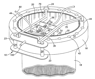
FIG. 1 shows a first embodiment of the welding jig 10 of the present
invention, comprising a frame member 12 (which itself is substantially planar
and
adapted to overlie a substantially planar face 14 of a bolting flange 16 of a
pipe 18).
Welding jig 10 , when used for the purposes disclosed herein, is disposed on
said
bolting flange 16 substantially perpendicular to a longitudinal axis 17 of
pipe 18.
Pipe 18 typically is (although it need not necessarily be) an abrasion-
resistant pipe, having a plurality of chromium-carbide wear-resistant rods 20
welded
longitudinally along the interior surface 22 of the pipe 18 as shown in Fig.'s
I & 3,
or alternatively having a plurality of circumferentially wound chromium
carbide wear-
resistant rods 20 welded to the circumference of the interior surface 22 of
pipe 18, as
shown in Fig.s 2 & 6.
Bolting flange 16 of pipe 18 typically possesses a planar surface 40, and has
a circular outer periphery 26 . A plurality of bolt holes 42 are provided
within a
circular bolt hole pattern 44 on bolting flange 18, which are used for bolting
two
mating bolting flanges together to form a continuous pipe. At least one or
both of the
-13 -
CAL LAW\ 1627687\1
CA 02714515 2010-09-14
circular outer periphery 26 or the circular bolt hole pattern 44 are perfectly
concentric
about center point "C" of bolting flange 16 and pipe 18.
Two spaced-apart contact points 23 on welding jig. 10 in the form of two
spaced-apart rollers 24 are provided at one end of frame member 12 in the
first
embodiment of the welding jig 10 shown in Fig.s 1-4. Rollers 24 in the
embodiment
shown in Fig.s 1-4 are each adapted to contact (and remain in contacting
engagement during welding) with circular outer periphery 26 of bolting flange
16.
Circular outer periphery 26 in the embodiment shown in Fig.'s 1-4 is perfectly
concentric about center "C" of pipe 18.
Welding jig 10 further comprises a chill block 30, which as best shown in Fig.
3 is situated substantially intermediate said two contact points in the form
of rollers
24 on welding jig 10. Chill block 30 is typically comprised of a highly
thermally
conductive metal, such as copper, and is adapted to be supplied via tubing 80
with
cooling fluid. Specifically chill block 30 is adapted to allow cooling fluid
to be
provided to it for the purpose of circulating within it to cool chill block 30
during
welding, and provision is further made for connection to additional tubing 81
to
permit removal of such cooling fluid from chill block 30. For this purpose
fluid inlet
and outlet couplings, in the form of standard fluid coupling nipples 70, are
provided
on chill block 30, and are typically threadably inserted into chill block 30
to allow inlet
tubing 80 and outlet tubing 81 to be respectively connected thereto to supply
cooling
fluid during welding.
Chill block 30 possesses a convexly-curved outer surface 34, having a
curvature corresponding to a desired inner diameter (2x dimension 'R') of pipe
18
(see Fig. 3) . Convexly-curved outer surface 34 is positioned by frame member
12
of welding jig 10 proximate the interior surface of pipe 18, as shown in each
of Figs.
1-6.
-14 -
CAL LAW\ 1627687\1
CA 02714515 2010-09-14
Convexly-curved outer surface 34 of chill block 30 is held at a desired
diameter of the interior of pipe 18 by an elongate threaded member 36.
Elongate
threaded member 36 can be turned via turnbuckle 38 to adjust the radial
positioning
of chill block 30 and curved outer surface 34 thereon within the interior of
bolting
flange 16.
Because circular outer periphery 26 (in the embodiment shown in Fig.s 1-4)
is perfectly concentric about center "C" of bolting flange 16, curved outer
surface 34
of chill block 30 can be maintained concentric with center "C" by elongate
members
50 of frame member 12 regardless of the radial position of the welding jig 10
on
bolting flange 16. (eg. cf Fig.s 1 & 2). Specifically, chill block 30 is
preferably
centered precisely intermediate two contact points 23 (ie rollers 24) on
circular outer
periphery 26, and thus center of curvature of arcuate surface 34 will
precisely fall at
center point "C" of pipe 18. This is because of the geometric principle that a
line
perpendicular to and which equally bisects a line connecting two points on the
periphery of a circle need necessarily pass through the center of the circle.
Elongate threaded member 36 preferably passes through center point "C", as
best
shown in Fig.s 2 & 6, in order that arcuate surface 34 be concentric with
circular
outer periphery 26.
Where circular bolt hole pattern 44 on bolting flange 16 is also concentric
about center point "C" , and where the outer periphery 26 of bolting flange 16
may or
may not be perfectly circular or not perfectly concentric about center point
"C", in
such circumstances an alternative embodiment and manner of operation of the
welding jig 10 of the present invention is provided, as shown in Fig.s 5 & 6.
Specifically, in such embodiment where circular bolt hole pattern 44 on
bolting flange 16 is concentric with center "C" of bolting flange 18, welding
jig 10 as
shown in Fig.s 5 & 6 is provided with a pair of spaced apart contact points at
one
end of jig 10 in the form of removable pin members 60, which may each be
inserted
-15-
CAL-LAVA 1627687\1
CA 02714515 2010-09-14
in a corresponding pair of bolt holes 42 within circular bolt pattern 44. As
chill
block 30 is centered precisely intermediate two contact points (ie removable
pin
members 60) on circular outer periphery 26 as shown in Fig.'s 5 & 6), chill
block 30
and in particular convexly curved surface 34 thereof will be kept perfectly
concentric
about center "C" of bolting flange 18.
Removable pins 60 (which serve to position welding jig 10 on bolting flange
16 so that arcuate surface 34 is concentric with circular bolt hole pattern
44) are of a
diameter substantially corresponding to bolt holes 42 within flange member 16,
and
may be provided with gripping members 61 which facilitate easy handling and
prevent pins 60 from slipping through bolt holes 42.
In a preferred embodiment of the welding jig 10 of the present invention, at a
distal end 72 thereof opposite contact points 23 possesses means to overlie
and be
supported by bolting flange 16. In a preferred embodiment such means comprises
a
pair of rollers 24 disposed on elongate arms 75, as most clearly shown in
Fig.'s 1,3,
4,5,& 6. In a preferred embodiment as shown in Fig. 4, adjustment means 76
such
as shown in Fig. 4 may be provided on elongate arms 75 of frame 12 to allow
respective adjustment of the position of rollers 24 overlying bolting flange
16.
The manner of operation of the welding jig 10 in creating a pipe 18 having a
flange 16 wherein the interior surface 22 thereof is made concentric with the
circular
outer periphery 26 of the bolting flange 16 and/or the circular bolt hole
pattern 44 on
bolting flange 16 will now be described in detail.
Welding jig 10 is placed over planar face 14 of flange 16, substantially
perpendicular to longitudinal axis 17 of pipe 18.
In an instance where the circular outer periphery 26 of bolting flange 16 is
perfectly circular and concentric about center "C" of flange 16, a welding jig
10 as
-16-
CAL _LAW\ 1627687\1
CA 02714515 2010-09-14
shown in Fig.'s 1-4 is used, having a pair of spaced apart contact points 23
in the
form of rollers 24 , which are placed in contact with the circular outer
periphery 26 of
bolting flange 16. Arcuate curved surface 34 of chill block 30 is positioned
via
turnbuckle 38 on elongate threaded member 36 against the inner surface 22 of
pipe
18, at a distance "R" corresponding to the desired uniform radius of inner
surface 22
of pipe 18.
Cooling fluid is provided via tubing 80 to chill block 30, and removed from
chill block 30 via additional tubing 81 . Weld material using welding gun
(typically
tungsten inert gas welding gun, but other forms of welding may be used as will
occur
to a person of skill in the art), to uniformly deposit material (typically
wear resistant
material) in the interstitial distance between existing wear material on inner
surface
22 of pipe 18, and the arcuate curved surface 34 of chill block 30.
Upon solidification of such deposited material on the inner surface 22 of pipe
18, welding jig 10, and in particular rollers 24 in contact with circular
periphery 26, is
repositioned by sliding rollers 24 along circular periphery 26, thereby moving
chill
block 30 and curved surface 34 thereof to a new position contacting inner
surface 22
of pipe 18. Repositioining may be assisted by use of handle member 100
positioned
intermediate rollers 24 proximate points of contact with circular periphery
26.
To reposition such arcuate surface 34 and welding jig, it may be necessary
to unscrew turnbuckle 38, reposition welding jig 10, and rescrew turnbuckle 38
to
return arcuate surface 34 of chill block 30 to the desired radial position
"R".
The above welding and repositioning steps are sequentially repeated as
the chill block 30 is incrementally repositioned around the inner
circumference of
pipe 18, until the entirety of inner surface 22 of pipe 18 has had weld
material
uniformly deposited thereon , thereby producing an inner surface 22 of a
diameter
concentric with the outer periphery 26 of bolting flange 16.
-17 -
CAL LAW\ 1627687\1
CA 02714515 2010-09-14
In an instance with regard to a bolting flange 16 on a pipe 18 has a circular
bolt hole pattern 44 perfectly circular and concentric within center "C" of
pipe 18,
and particularly in a situation where outer periphery 26 of bolting flange 16
is not
perfectly circular and/or not concentric with center "C" of pipe 18, a welding
jig of
slightly modified configuration is used, namely of a configuration as shown in
Fig's 5
& 6.
Specifically, in such situation, welding jig 10 is provided with two contact
points in the form of insertable pins 60, apertures for such pins 60 being
provided a
predetermined distance apart in frame 12 corresponding to the shortest
distance
between a predetermined number of bolt holes 42 on bolting flange 16. Jig 10
is
placed over planar face 14 of bolting flange 16, and pins 60 inserted within a
pair of
bolt holes 42 within circular bolt hole pattern 44, to thereby stabilize and
temporarily
secure jig 10 to bolting face 16 of pipe 18. Curved surface 34 of chill block
30 is
positioned at a desired radial distance "R" (the desired uniform and
concentric radius
of pipe 18 which is desired to be created) via turnbuckle 38 on elongate
threaded
member 36 .
An identical procedure identical to the process described above in respect of
the alternative embodiment of the welding jig 10 is then carried out, namely a
cooling
fluid is supplied to the chill block 30, and a weld material 85 is built up by
weld
deposition in the interstitial area between the inner surface 22 of pipe 18
and the
arcuate curved surface 34. Upon solidification of any weld material, pins 60
are then
raised, and the welding jig repositioned by an incremental rotation about
center
point "C", which repositioning may be assisted by use of handle member 100 .
Again, , it may be necessary to unscrew turnbuckle 38, reposition welding jig
10, and
rescrew turnbuckle 38 to return arcuate surface 34 of chill block 30 to the
desired
radial position "R".
Many variations and modifications will now occur to those skilled in the art.
-18 -
CAL -LAWN 1627687\1
CA 02714515 2010-09-14
For a complete definition of the invention and its intended scope, reference
is to be made to the summary of the invention and the appended claims read
together with and considered with the disclosure and drawings herein.
-19 -
CAL LAW\ 1627687\1