Language selection

Search

Patent 2714734 Summary

Third-party information liability

Some of the information on this Web page has been provided by external sources. The Government of Canada is not responsible for the accuracy, reliability or currency of the information supplied by external sources. Users wishing to rely upon this information should consult directly with the source of the information. Content provided by external sources is not subject to official languages, privacy and accessibility requirements.

Claims and Abstract availability

Any discrepancies in the text and image of the Claims and Abstract are due to differing posting times. Text of the Claims and Abstract are posted:

  • At the time the application is open to public inspection;
  • At the time of issue of the patent (grant).
(12) Patent Application: (11) CA 2714734
(54) English Title: DOWEL BOLT OF A CONNECTION DEVICE
(54) French Title: BOULON DE CENTRAGE DE DISPOSITIF DE RACCORDEMENT
Status: Deemed Abandoned and Beyond the Period of Reinstatement - Pending Response to Notice of Disregarded Communication
Bibliographic Data
(51) International Patent Classification (IPC):
  • F16B 12/10 (2006.01)
  • F16B 05/01 (2006.01)
  • F16B 05/02 (2006.01)
  • F16B 12/22 (2006.01)
  • F16B 35/06 (2006.01)
(72) Inventors :
  • LUETKENHOEENER, MARCO (Germany)
(73) Owners :
  • HETTICH-HEINZE GMBH & CO. KG
(71) Applicants :
  • HETTICH-HEINZE GMBH & CO. KG (Germany)
(74) Agent: SMART & BIGGAR LP
(74) Associate agent:
(45) Issued:
(22) Filed Date: 2010-09-13
(41) Open to Public Inspection: 2011-03-19
Availability of licence: N/A
Dedicated to the Public: N/A
(25) Language of filing: English

Patent Cooperation Treaty (PCT): No

(30) Application Priority Data:
Application No. Country/Territory Date
20 2009 012 750.8 (Germany) 2009-09-19

Abstracts

English Abstract


Dowel bolt (2) of a connection device (1) for connecting a first element to a
second element (4), having a fastening part in the form of a threaded pin (7)
for
fixing on the first element and a dowel shaft (6) connected thereto having a
head
part (5), which a clamping cam of a clamping part (3) in the second element
(4)
can engage behind, the threaded pin (7) and the dowel shaft (6) being
implemented as separate components and being connected to one another via a
link guide (8) running perpendicularly to the longitudinal axis of the dowel
bolt (2)
in a formfitting manner in the direction of the longitudinal axis of the dowel
bolt
(2), but displaceable to one another transversely to this longitudinal axis.


Claims

Note: Claims are shown in the official language in which they were submitted.

7
THE EMBODIMENTS OF THE INVENTION IN WHICH AN EXCLUSIVE
PROPERTY OR PRIVILEGE IS CLAIMED ARE DEFINED AS FOLLOWS:
1. A dowel bolt (2) of a connection device (1) for connecting a first element
to a second element (4), having a fastening part in the form of a threaded
pin (7) for fixing on the first element and a dowel shaft (6) connected
thereto having a head part (5), which a clamping cam of a clamping part
(3) in the second element (4) can engage behind, characterized in that
the threaded pin (7) and the dowel shaft (6) are implemented as separate
components and are connected to one another, via a link guide (8)
running perpendicularly to the longitudinal axis of the dowel bolt (2), in a
formfitting manner in the direction of the longitudinal axis of the dowel bolt
(2), but displaceable to one another transversely to this longitudinal axis.
2. The dowel bolt according to Claim 1, characterized in that the link guide
(8) is implemented in the form of a rectangular link block (9) and a guide
part (11) having an undercut, C-shaped groove (10).
3. The dowel bolt according to Claim 1, characterized in that the link guide
(8) is implemented in the form of a dovetail guide.
4. The dowel bolt according to one of the preceding claims, characterized
in that fine teeth having a small gauge are provided on the contact
surfaces of the link guide (8).
5. The dowel bolt according to one of the preceding claims, characterized
in that the link block (9) of the link guide (8) is pressed in a spring-loaded
manner against its contact surfaces to the longitudinal groove (10).
6. The dowel bolt according to one of the preceding claims, characterized
in that the threaded pin (7) is implemented as a self-tapping screw.

8
7. The dowel bolt according to one of the preceding claims, characterized
in that the threaded pin (7) is equipped with a shaped tip toward its free
end.
8. The dowel bolt according to one of the preceding claims, characterized
in that a tool receptacle (12) in the form of a slot or a cross slot or the
like
is provided in the area of the base groove of the groove (10) inside the
guide part (11), this tool receptacle being coaxial to the longitudinal axis
of
the threaded pin (7).
9. The dowel bolt according to one of the preceding claims, characterized
in that a screwing tool can be externally placed on the body of the link
guide (8).

Description

Note: Descriptions are shown in the official language in which they were submitted.


CA 02714734 2010-09-13
1
DOWEL BOLT OF A CONNECTION DEVICE
The present invention relates to a dowel bolt of a connection device for
connecting a first element to a second element, having a fastening part in the
form of a threaded pin for fixing on the first element and a dowel shaft
connected
thereto having a head part, which a clamping cam of a clamping part in the
second element can engage behind.
Connection devices of two elements are used in furniture construction in order
to
connect together two furniture parts which run perpendicularly to one another,
but also for the purpose of fixing shelf boards directly on a building wall.
Because the present invention only relates to the dowel bolt of a
corresponding
connection device, it is only noted as an explanation that the clamping device
as
the second connection part is a fitting part fixable in the second element,
within
which a clamping cam provided with eccentric clamping curves is situated, the
clamping cam engaging behind the head part in case of connection, so that by
rotating the clamping cam, the two elements to be connected to one another are
tightened fixedly on one another.
Corresponding connection devices are each used in pairs, on the one hand, to
ensure a stable connection and, on the other hand, to ensure the twist lock of
the
connection. To transmit greater forces, more than two connection devices may
also be situated.
Because the distances of two clamping parts to one another within the second
element are not changeable, it is necessary to situate the two dowel bolts
inside
the first element at exactly the same distance to one another. Because of
unavoidable tolerances, this cannot always be maintained exactly, so that
problems can occur during the installation.

CA 02714734 2010-09-13
2
The present invention is based on the object of providing a dowel bolt of the
type
according to the species, which overcomes these problems and allows the
distance of two such dowel bolts to be readily oriented to the specified
distance
of two clamping parts to one another.
This object is achieved according to the invention in that the threaded pin
and
the dowel shaft are implemented as separate components and are connected to
one another, via a link guide running perpendicular to the longitudinal axis
of the
dowel bolt, in a formfitting manner in the direction of the longitudinal axis
of the
dowel bolts, but displaceable transversely to this longitudinal axis.
Through this simple design measure, it is possible to laterally displace a
dowel
shaft of a dowel bolt in relation to the threaded pin, so that the axial
distance of
two dowel shafts relative to one another can be adapted exactly to the
specified
distance of two clamping parts. The condition for this purpose is solely that
the
dowel shaft of a first connection device is displaceable in the direction of
an
imaginary connection line to the dowel shaft of a second connection device by
corresponding orientation of the link guide.
If the displacement direction of the dowel shaft of the second connection
device
is oriented perpendicular to the displacement direction of the dowel shaft of
the
first connection device, a horizontal orientation of the first element in
relation to
the second element is also even readily possible.
Through the design of the dowel bolt according to the present invention, a
significant installation simplification is thus achieved by the adjustment
capabilities, which result from the possibility of displacing the dowel shaft
in
relation to the threaded pin.
Further features of the invention are the subject matter of subclaims.

CA 02714734 2010-09-13
3
Exemplary embodiments of the invention are shown in the appended drawings
and are described in greater detail hereafter.
In the figures:
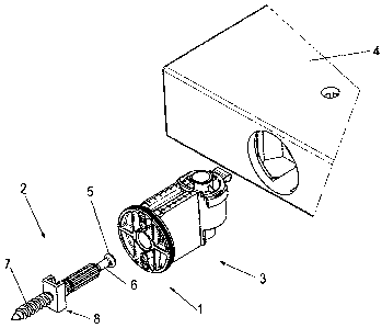
Figure 1 shows a perspective exploded view of a connection device
having a dowel bolt according to the invention
Figure 2 shows a perspective view, corresponding to Figure 1, having
preinstalled clamping part
Figure 3 shows a perspective view of a dowel bolt according to the
invention
Figures 4 and 5 show views of the dowel bolt from Figure 3 from two viewing
directions offset by 90 to one another
Figure 6 shows a perspective view of the dowel bolt according to
Figures 3 - 5, a fastening part of the dowel bolt in the form of a
threaded pin being separated from a dowel shaft having a
head part
Figure 7 shows a view in the direction of the arrow VII in Figure 6.
Figures 1 and 2 show, in particular for orientation purposes, a connection
device
1, which comprises a dowel bolt 2 and a clamping part 3, and is used for the
purpose of connecting a first element (not shown) to a second element 4. The
first element (not shown), on which the dowel bolt 2 is fixable, can be a
building
wall or also a furniture construction plate, as is shown in the case of the
second
element 4 for receiving the clamping part 3.

CA 02714734 2010-09-13
4
The clamping part 3 is fixed in a way known per se in a furniture plate and is
provided with a clamping cam, having an eccentric clamping curve, which
engages behind a head part 5 of a dowel shaft 6 of the dowel bolt 2 in case of
connection. As further shown in Figures 1 and 2, the dowel bolt 2 is equipped
with a fastening part in the form of a threaded pin 7, which allows the entire
dowel bolt 2 to be screwed tight on a first element.
As Figures 3 - 6 show in greater detail, the threaded pin 7 and the dowel
shaft 6
of the dowel bolt 2 are implemented as separate components and are
connectable to one another via a link guide, which is provided as a whole with
the reference numeral 8. As Figures 3 - 6 show in particular, the dowel shaft
6 is
equipped on its lower end facing toward the threaded pin 7 with a rectangle
forming a link block 9, which is insertable into a corresponding undercut C-
shaped groove 10 of a guide part 11 and is longitudinally displaceable within
the
groove 10. Because a twist-locked connection between dowel shaft 6 and
threaded pin 7 results through the rectangle 9 of the dowel shaft 6 engaging
in
the undercut groove 10 of the guide part 11, the dowel bolt 2, assuming
corresponding obstruction against displacement and coaxial orientation, can be
screwed in the assembled state, as shown in Figures 3 - 5, like a known, one-
piece dowel bolt into a first element, the condition for this purpose being
that the
head part 5 of the dowel shaft 6 is equipped with a tool receptacle 12 in the
form
of a slot or a cross slot, for example.
However, it is also conceivable to provide a corresponding tool receptacle 12
in
the area of the groove base of the groove 10 of the guide part 11, so that it
is
possible to firstly screw the threaded pin 7 into a first element and only
then to
insert the rectangle 9 of the dowel shaft 6 into the groove 10. The advantage
of
this design is that the screwing of the threaded pin 7 into a first element
becomes more secure.
Furthermore, it is also conceivable that a screwing-in tool can also engage
externally on the body of the link guide 8, for example, an open-end wrench,
or

CA 02714734 2010-09-13
the body of the link guide 8 can receive the contour of a hexagon for the tool
receptacle of a hex key. The general advantage of the two-piece dowel bolt
design can be seen in that the dowel shaft 6 can be displaced transversely to
the
longitudinal axis of the threaded pin 7, whereby adjustments become readily
5 possible.
Fundamentally, it is desirable for the displacement of the dowel shaft 6
transversely to the longitudinal axis of the threaded pin 7 to be
comparatively
smooth, without the danger existing that the dowel shaft 6 could be displaced
unintentionally in relation to the longitudinal axis of the threaded pin 7.
For this
purpose, it can be helpful if contact surfaces of the link guide 8 pressing
against
one another in case of load are provided with fine teeth having small gauge.
It is
also conceivable to provide a spring inside the link guide 8, which presses
the
link block in the form of the rectangle 9 against the corresponding contact
surfaces of the guide part 11.
Instead of a link guide 8 in the meaning shown, i.e., having a C-shaped
undercut
groove 10 and a rectangle 9 as the link block, of course, the known form of a
dovetail guide can also be selected here.
It is preferable that the threaded pin 7 is fundamentally implemented as a
self-
tapping screw and advantageously is shaped to form a tip, so that the threaded
pin 7 can be screwed into a first element without the necessity of previously
introducing a drilled hole into this first element, which particularly comes
into
consideration in the case of furniture construction plates, of course.

CA 02714734 2010-09-13
6
List of reference numerals
1 connection device
2 dowel bolt
3 clamping part
4 element
5 head part
6 dowel shaft
7 threaded pin
8 link guide
9 rectangle
10 groove
11 guide part
12 tool receptacle

Representative Drawing
A single figure which represents the drawing illustrating the invention.
Administrative Status

2024-08-01:As part of the Next Generation Patents (NGP) transition, the Canadian Patents Database (CPD) now contains a more detailed Event History, which replicates the Event Log of our new back-office solution.

Please note that "Inactive:" events refers to events no longer in use in our new back-office solution.

For a clearer understanding of the status of the application/patent presented on this page, the site Disclaimer , as well as the definitions for Patent , Event History , Maintenance Fee  and Payment History  should be consulted.

Event History

Description Date
Application Not Reinstated by Deadline 2016-09-14
Time Limit for Reversal Expired 2016-09-14
Inactive: Abandon-RFE+Late fee unpaid-Correspondence sent 2015-09-14
Deemed Abandoned - Failure to Respond to Maintenance Fee Notice 2015-09-14
Application Published (Open to Public Inspection) 2011-03-19
Inactive: Cover page published 2011-03-18
Inactive: Filing certificate - No RFE (English) 2011-02-09
Inactive: Inventor deleted 2011-02-09
Inactive: Filing certificate - No RFE (English) 2010-11-22
Inactive: IPC assigned 2010-11-08
Inactive: First IPC assigned 2010-11-08
Inactive: IPC assigned 2010-11-08
Application Received - Regular National 2010-10-04
Amendment Received - Voluntary Amendment 2010-09-30

Abandonment History

Abandonment Date Reason Reinstatement Date
2015-09-14

Maintenance Fee

The last payment was received on 2014-06-30

Note : If the full payment has not been received on or before the date indicated, a further fee may be required which may be one of the following

  • the reinstatement fee;
  • the late payment fee; or
  • additional fee to reverse deemed expiry.

Patent fees are adjusted on the 1st of January every year. The amounts above are the current amounts if received by December 31 of the current year.
Please refer to the CIPO Patent Fees web page to see all current fee amounts.

Fee History

Fee Type Anniversary Year Due Date Paid Date
Application fee - standard 2010-09-13
MF (application, 2nd anniv.) - standard 02 2012-09-13 2012-07-10
MF (application, 3rd anniv.) - standard 03 2013-09-13 2013-06-06
MF (application, 4th anniv.) - standard 04 2014-09-15 2014-06-30
Owners on Record

Note: Records showing the ownership history in alphabetical order.

Current Owners on Record
HETTICH-HEINZE GMBH & CO. KG
Past Owners on Record
MARCO LUETKENHOEENER
Past Owners that do not appear in the "Owners on Record" listing will appear in other documentation within the application.
Documents

To view selected files, please enter reCAPTCHA code :


To view images, click a link in the Document Description column. To download the documents, select one or more checkboxes in the first column and then click the "Download Selected in PDF format (Zip Archive)" or the "Download Selected as Single PDF" button.

List of published and non-published patent-specific documents on the CPD .

If you have any difficulty accessing content, you can call the Client Service Centre at 1-866-997-1936 or send them an e-mail at CIPO Client Service Centre.


Document
Description 
Date
(yyyy-mm-dd) 
Number of pages   Size of Image (KB) 
Description 2010-09-12 6 206
Claims 2010-09-12 2 56
Abstract 2010-09-12 1 18
Drawings 2010-09-12 4 68
Representative drawing 2011-02-20 1 11
Filing Certificate (English) 2010-11-21 1 156
Filing Certificate (English) 2011-02-08 1 157
Reminder of maintenance fee due 2012-05-14 1 112
Reminder - Request for Examination 2015-05-13 1 116
Courtesy - Abandonment Letter (Request for Examination) 2015-11-08 1 164
Courtesy - Abandonment Letter (Maintenance Fee) 2015-11-08 1 172
Correspondence 2011-01-30 2 114
Prosecution correspondence 2010-09-29 1 36