Sélection de la langue

Search

Sommaire du brevet 2714734 

Énoncé de désistement de responsabilité concernant l'information provenant de tiers

Une partie des informations de ce site Web a été fournie par des sources externes. Le gouvernement du Canada n'assume aucune responsabilité concernant la précision, l'actualité ou la fiabilité des informations fournies par les sources externes. Les utilisateurs qui désirent employer cette information devraient consulter directement la source des informations. Le contenu fourni par les sources externes n'est pas assujetti aux exigences sur les langues officielles, la protection des renseignements personnels et l'accessibilité.

Disponibilité de l'Abrégé et des Revendications

L'apparition de différences dans le texte et l'image des Revendications et de l'Abrégé dépend du moment auquel le document est publié. Les textes des Revendications et de l'Abrégé sont affichés :

  • lorsque la demande peut être examinée par le public;
  • lorsque le brevet est émis (délivrance).
(12) Demande de brevet: (11) CA 2714734
(54) Titre français: BOULON DE CENTRAGE DE DISPOSITIF DE RACCORDEMENT
(54) Titre anglais: DOWEL BOLT OF A CONNECTION DEVICE
Statut: Réputée abandonnée et au-delà du délai pour le rétablissement - en attente de la réponse à l’avis de communication rejetée
Données bibliographiques
(51) Classification internationale des brevets (CIB):
  • F16B 12/10 (2006.01)
  • F16B 05/01 (2006.01)
  • F16B 05/02 (2006.01)
  • F16B 12/22 (2006.01)
  • F16B 35/06 (2006.01)
(72) Inventeurs :
  • LUETKENHOEENER, MARCO (Allemagne)
(73) Titulaires :
  • HETTICH-HEINZE GMBH & CO. KG
(71) Demandeurs :
  • HETTICH-HEINZE GMBH & CO. KG (Allemagne)
(74) Agent: SMART & BIGGAR LP
(74) Co-agent:
(45) Délivré:
(22) Date de dépôt: 2010-09-13
(41) Mise à la disponibilité du public: 2011-03-19
Licence disponible: S.O.
Cédé au domaine public: S.O.
(25) Langue des documents déposés: Anglais

Traité de coopération en matière de brevets (PCT): Non

(30) Données de priorité de la demande:
Numéro de la demande Pays / territoire Date
20 2009 012 750.8 (Allemagne) 2009-09-19

Abrégés

Abrégé anglais


Dowel bolt (2) of a connection device (1) for connecting a first element to a
second element (4), having a fastening part in the form of a threaded pin (7)
for
fixing on the first element and a dowel shaft (6) connected thereto having a
head
part (5), which a clamping cam of a clamping part (3) in the second element
(4)
can engage behind, the threaded pin (7) and the dowel shaft (6) being
implemented as separate components and being connected to one another via a
link guide (8) running perpendicularly to the longitudinal axis of the dowel
bolt (2)
in a formfitting manner in the direction of the longitudinal axis of the dowel
bolt
(2), but displaceable to one another transversely to this longitudinal axis.

Revendications

Note : Les revendications sont présentées dans la langue officielle dans laquelle elles ont été soumises.


7
THE EMBODIMENTS OF THE INVENTION IN WHICH AN EXCLUSIVE
PROPERTY OR PRIVILEGE IS CLAIMED ARE DEFINED AS FOLLOWS:
1. A dowel bolt (2) of a connection device (1) for connecting a first element
to a second element (4), having a fastening part in the form of a threaded
pin (7) for fixing on the first element and a dowel shaft (6) connected
thereto having a head part (5), which a clamping cam of a clamping part
(3) in the second element (4) can engage behind, characterized in that
the threaded pin (7) and the dowel shaft (6) are implemented as separate
components and are connected to one another, via a link guide (8)
running perpendicularly to the longitudinal axis of the dowel bolt (2), in a
formfitting manner in the direction of the longitudinal axis of the dowel bolt
(2), but displaceable to one another transversely to this longitudinal axis.
2. The dowel bolt according to Claim 1, characterized in that the link guide
(8) is implemented in the form of a rectangular link block (9) and a guide
part (11) having an undercut, C-shaped groove (10).
3. The dowel bolt according to Claim 1, characterized in that the link guide
(8) is implemented in the form of a dovetail guide.
4. The dowel bolt according to one of the preceding claims, characterized
in that fine teeth having a small gauge are provided on the contact
surfaces of the link guide (8).
5. The dowel bolt according to one of the preceding claims, characterized
in that the link block (9) of the link guide (8) is pressed in a spring-loaded
manner against its contact surfaces to the longitudinal groove (10).
6. The dowel bolt according to one of the preceding claims, characterized
in that the threaded pin (7) is implemented as a self-tapping screw.

8
7. The dowel bolt according to one of the preceding claims, characterized
in that the threaded pin (7) is equipped with a shaped tip toward its free
end.
8. The dowel bolt according to one of the preceding claims, characterized
in that a tool receptacle (12) in the form of a slot or a cross slot or the
like
is provided in the area of the base groove of the groove (10) inside the
guide part (11), this tool receptacle being coaxial to the longitudinal axis
of
the threaded pin (7).
9. The dowel bolt according to one of the preceding claims, characterized
in that a screwing tool can be externally placed on the body of the link
guide (8).

Description

Note : Les descriptions sont présentées dans la langue officielle dans laquelle elles ont été soumises.

CA 02714734 2010-09-13
1
DOWEL BOLT OF A CONNECTION DEVICE
The present invention relates to a dowel bolt of a connection device for
connecting a first element to a second element, having a fastening part in the
form of a threaded pin for fixing on the first element and a dowel shaft
connected
thereto having a head part, which a clamping cam of a clamping part in the
second element can engage behind.
Connection devices of two elements are used in furniture construction in order
to
connect together two furniture parts which run perpendicularly to one another,
but also for the purpose of fixing shelf boards directly on a building wall.
Because the present invention only relates to the dowel bolt of a
corresponding
connection device, it is only noted as an explanation that the clamping device
as
the second connection part is a fitting part fixable in the second element,
within
which a clamping cam provided with eccentric clamping curves is situated, the
clamping cam engaging behind the head part in case of connection, so that by
rotating the clamping cam, the two elements to be connected to one another are
tightened fixedly on one another.
Corresponding connection devices are each used in pairs, on the one hand, to
ensure a stable connection and, on the other hand, to ensure the twist lock of
the
connection. To transmit greater forces, more than two connection devices may
also be situated.
Because the distances of two clamping parts to one another within the second
element are not changeable, it is necessary to situate the two dowel bolts
inside
the first element at exactly the same distance to one another. Because of
unavoidable tolerances, this cannot always be maintained exactly, so that
problems can occur during the installation.

CA 02714734 2010-09-13
2
The present invention is based on the object of providing a dowel bolt of the
type
according to the species, which overcomes these problems and allows the
distance of two such dowel bolts to be readily oriented to the specified
distance
of two clamping parts to one another.
This object is achieved according to the invention in that the threaded pin
and
the dowel shaft are implemented as separate components and are connected to
one another, via a link guide running perpendicular to the longitudinal axis
of the
dowel bolt, in a formfitting manner in the direction of the longitudinal axis
of the
dowel bolts, but displaceable transversely to this longitudinal axis.
Through this simple design measure, it is possible to laterally displace a
dowel
shaft of a dowel bolt in relation to the threaded pin, so that the axial
distance of
two dowel shafts relative to one another can be adapted exactly to the
specified
distance of two clamping parts. The condition for this purpose is solely that
the
dowel shaft of a first connection device is displaceable in the direction of
an
imaginary connection line to the dowel shaft of a second connection device by
corresponding orientation of the link guide.
If the displacement direction of the dowel shaft of the second connection
device
is oriented perpendicular to the displacement direction of the dowel shaft of
the
first connection device, a horizontal orientation of the first element in
relation to
the second element is also even readily possible.
Through the design of the dowel bolt according to the present invention, a
significant installation simplification is thus achieved by the adjustment
capabilities, which result from the possibility of displacing the dowel shaft
in
relation to the threaded pin.
Further features of the invention are the subject matter of subclaims.

CA 02714734 2010-09-13
3
Exemplary embodiments of the invention are shown in the appended drawings
and are described in greater detail hereafter.
In the figures:
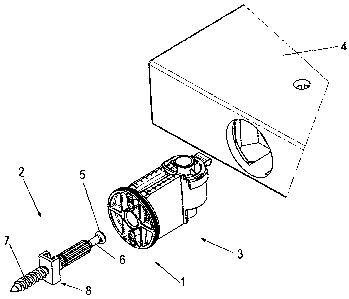
Figure 1 shows a perspective exploded view of a connection device
having a dowel bolt according to the invention
Figure 2 shows a perspective view, corresponding to Figure 1, having
preinstalled clamping part
Figure 3 shows a perspective view of a dowel bolt according to the
invention
Figures 4 and 5 show views of the dowel bolt from Figure 3 from two viewing
directions offset by 90 to one another
Figure 6 shows a perspective view of the dowel bolt according to
Figures 3 - 5, a fastening part of the dowel bolt in the form of a
threaded pin being separated from a dowel shaft having a
head part
Figure 7 shows a view in the direction of the arrow VII in Figure 6.
Figures 1 and 2 show, in particular for orientation purposes, a connection
device
1, which comprises a dowel bolt 2 and a clamping part 3, and is used for the
purpose of connecting a first element (not shown) to a second element 4. The
first element (not shown), on which the dowel bolt 2 is fixable, can be a
building
wall or also a furniture construction plate, as is shown in the case of the
second
element 4 for receiving the clamping part 3.

CA 02714734 2010-09-13
4
The clamping part 3 is fixed in a way known per se in a furniture plate and is
provided with a clamping cam, having an eccentric clamping curve, which
engages behind a head part 5 of a dowel shaft 6 of the dowel bolt 2 in case of
connection. As further shown in Figures 1 and 2, the dowel bolt 2 is equipped
with a fastening part in the form of a threaded pin 7, which allows the entire
dowel bolt 2 to be screwed tight on a first element.
As Figures 3 - 6 show in greater detail, the threaded pin 7 and the dowel
shaft 6
of the dowel bolt 2 are implemented as separate components and are
connectable to one another via a link guide, which is provided as a whole with
the reference numeral 8. As Figures 3 - 6 show in particular, the dowel shaft
6 is
equipped on its lower end facing toward the threaded pin 7 with a rectangle
forming a link block 9, which is insertable into a corresponding undercut C-
shaped groove 10 of a guide part 11 and is longitudinally displaceable within
the
groove 10. Because a twist-locked connection between dowel shaft 6 and
threaded pin 7 results through the rectangle 9 of the dowel shaft 6 engaging
in
the undercut groove 10 of the guide part 11, the dowel bolt 2, assuming
corresponding obstruction against displacement and coaxial orientation, can be
screwed in the assembled state, as shown in Figures 3 - 5, like a known, one-
piece dowel bolt into a first element, the condition for this purpose being
that the
head part 5 of the dowel shaft 6 is equipped with a tool receptacle 12 in the
form
of a slot or a cross slot, for example.
However, it is also conceivable to provide a corresponding tool receptacle 12
in
the area of the groove base of the groove 10 of the guide part 11, so that it
is
possible to firstly screw the threaded pin 7 into a first element and only
then to
insert the rectangle 9 of the dowel shaft 6 into the groove 10. The advantage
of
this design is that the screwing of the threaded pin 7 into a first element
becomes more secure.
Furthermore, it is also conceivable that a screwing-in tool can also engage
externally on the body of the link guide 8, for example, an open-end wrench,
or

CA 02714734 2010-09-13
the body of the link guide 8 can receive the contour of a hexagon for the tool
receptacle of a hex key. The general advantage of the two-piece dowel bolt
design can be seen in that the dowel shaft 6 can be displaced transversely to
the
longitudinal axis of the threaded pin 7, whereby adjustments become readily
5 possible.
Fundamentally, it is desirable for the displacement of the dowel shaft 6
transversely to the longitudinal axis of the threaded pin 7 to be
comparatively
smooth, without the danger existing that the dowel shaft 6 could be displaced
unintentionally in relation to the longitudinal axis of the threaded pin 7.
For this
purpose, it can be helpful if contact surfaces of the link guide 8 pressing
against
one another in case of load are provided with fine teeth having small gauge.
It is
also conceivable to provide a spring inside the link guide 8, which presses
the
link block in the form of the rectangle 9 against the corresponding contact
surfaces of the guide part 11.
Instead of a link guide 8 in the meaning shown, i.e., having a C-shaped
undercut
groove 10 and a rectangle 9 as the link block, of course, the known form of a
dovetail guide can also be selected here.
It is preferable that the threaded pin 7 is fundamentally implemented as a
self-
tapping screw and advantageously is shaped to form a tip, so that the threaded
pin 7 can be screwed into a first element without the necessity of previously
introducing a drilled hole into this first element, which particularly comes
into
consideration in the case of furniture construction plates, of course.

CA 02714734 2010-09-13
6
List of reference numerals
1 connection device
2 dowel bolt
3 clamping part
4 element
5 head part
6 dowel shaft
7 threaded pin
8 link guide
9 rectangle
10 groove
11 guide part
12 tool receptacle

Dessin représentatif
Une figure unique qui représente un dessin illustrant l'invention.
États administratifs

2024-08-01 : Dans le cadre de la transition vers les Brevets de nouvelle génération (BNG), la base de données sur les brevets canadiens (BDBC) contient désormais un Historique d'événement plus détaillé, qui reproduit le Journal des événements de notre nouvelle solution interne.

Veuillez noter que les événements débutant par « Inactive : » se réfèrent à des événements qui ne sont plus utilisés dans notre nouvelle solution interne.

Pour une meilleure compréhension de l'état de la demande ou brevet qui figure sur cette page, la rubrique Mise en garde , et les descriptions de Brevet , Historique d'événement , Taxes périodiques et Historique des paiements devraient être consultées.

Historique d'événement

Description Date
Demande non rétablie avant l'échéance 2016-09-14
Le délai pour l'annulation est expiré 2016-09-14
Inactive : Abandon.-RE+surtaxe impayées-Corr envoyée 2015-09-14
Réputée abandonnée - omission de répondre à un avis sur les taxes pour le maintien en état 2015-09-14
Demande publiée (accessible au public) 2011-03-19
Inactive : Page couverture publiée 2011-03-18
Inactive : Certificat de dépôt - Sans RE (Anglais) 2011-02-09
Inactive : Inventeur supprimé 2011-02-09
Inactive : Certificat de dépôt - Sans RE (Anglais) 2010-11-22
Inactive : CIB attribuée 2010-11-08
Inactive : CIB en 1re position 2010-11-08
Inactive : CIB attribuée 2010-11-08
Demande reçue - nationale ordinaire 2010-10-04
Modification reçue - modification volontaire 2010-09-30

Historique d'abandonnement

Date d'abandonnement Raison Date de rétablissement
2015-09-14

Taxes périodiques

Le dernier paiement a été reçu le 2014-06-30

Avis : Si le paiement en totalité n'a pas été reçu au plus tard à la date indiquée, une taxe supplémentaire peut être imposée, soit une des taxes suivantes :

  • taxe de rétablissement ;
  • taxe pour paiement en souffrance ; ou
  • taxe additionnelle pour le renversement d'une péremption réputée.

Les taxes sur les brevets sont ajustées au 1er janvier de chaque année. Les montants ci-dessus sont les montants actuels s'ils sont reçus au plus tard le 31 décembre de l'année en cours.
Veuillez vous référer à la page web des taxes sur les brevets de l'OPIC pour voir tous les montants actuels des taxes.

Historique des taxes

Type de taxes Anniversaire Échéance Date payée
Taxe pour le dépôt - générale 2010-09-13
TM (demande, 2e anniv.) - générale 02 2012-09-13 2012-07-10
TM (demande, 3e anniv.) - générale 03 2013-09-13 2013-06-06
TM (demande, 4e anniv.) - générale 04 2014-09-15 2014-06-30
Titulaires au dossier

Les titulaires actuels et antérieures au dossier sont affichés en ordre alphabétique.

Titulaires actuels au dossier
HETTICH-HEINZE GMBH & CO. KG
Titulaires antérieures au dossier
MARCO LUETKENHOEENER
Les propriétaires antérieurs qui ne figurent pas dans la liste des « Propriétaires au dossier » apparaîtront dans d'autres documents au dossier.
Documents

Pour visionner les fichiers sélectionnés, entrer le code reCAPTCHA :


Pour visualiser une image, cliquer sur un lien dans la colonne description du document. Pour télécharger l'image (les images), cliquer l'une ou plusieurs cases à cocher dans la première colonne et ensuite cliquer sur le bouton "Télécharger sélection en format PDF (archive Zip)" ou le bouton "Télécharger sélection (en un fichier PDF fusionné)".

Liste des documents de brevet publiés et non publiés sur la BDBC .

Si vous avez des difficultés à accéder au contenu, veuillez communiquer avec le Centre de services à la clientèle au 1-866-997-1936, ou envoyer un courriel au Centre de service à la clientèle de l'OPIC.


Description du
Document 
Date
(aaaa-mm-jj) 
Nombre de pages   Taille de l'image (Ko) 
Description 2010-09-12 6 206
Revendications 2010-09-12 2 56
Abrégé 2010-09-12 1 18
Dessins 2010-09-12 4 68
Dessin représentatif 2011-02-20 1 11
Certificat de dépôt (anglais) 2010-11-21 1 156
Certificat de dépôt (anglais) 2011-02-08 1 157
Rappel de taxe de maintien due 2012-05-14 1 112
Rappel - requête d'examen 2015-05-13 1 116
Courtoisie - Lettre d'abandon (requête d'examen) 2015-11-08 1 164
Courtoisie - Lettre d'abandon (taxe de maintien en état) 2015-11-08 1 172
Correspondance 2011-01-30 2 114
Correspondance de la poursuite 2010-09-29 1 36