Language selection

Search

Patent 2714773 Summary

Third-party information liability

Some of the information on this Web page has been provided by external sources. The Government of Canada is not responsible for the accuracy, reliability or currency of the information supplied by external sources. Users wishing to rely upon this information should consult directly with the source of the information. Content provided by external sources is not subject to official languages, privacy and accessibility requirements.

Claims and Abstract availability

Any discrepancies in the text and image of the Claims and Abstract are due to differing posting times. Text of the Claims and Abstract are posted:

  • At the time the application is open to public inspection;
  • At the time of issue of the patent (grant).
(12) Patent: (11) CA 2714773
(54) English Title: ELECTRIC SHEARS
(54) French Title: CISAILLES ELECTRIQUES
Status: Deemed expired
Bibliographic Data
(51) International Patent Classification (IPC):
  • B26B 15/00 (2006.01)
(72) Inventors :
  • CHEN, WU (China)
  • YAMAOKA, TOSHINARI (China)
  • NIE, FANGJIE (China)
(73) Owners :
  • CHERVON LIMITED (China)
(71) Applicants :
  • CHERVON LIMITED (China)
(74) Agent: NORTON ROSE FULBRIGHT CANADA LLP/S.E.N.C.R.L., S.R.L.
(74) Associate agent:
(45) Issued: 2014-05-13
(22) Filed Date: 2010-09-14
(41) Open to Public Inspection: 2011-03-15
Examination requested: 2010-09-21
Availability of licence: N/A
(25) Language of filing: English

Patent Cooperation Treaty (PCT): No

(30) Application Priority Data:
Application No. Country/Territory Date
200920232508.9 China 2009-09-15

Abstracts

English Abstract

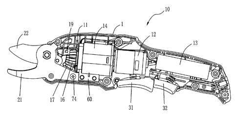
Electric shears include a housing, a motor within the housing, a transmission means including a reduction gearbox and a bevel gear pair, a fixed blade, a movable blade rotatably connected to the fixed blade and coupled with the motor via the transmission means, and a stroke-control 'means controlling the movable blade to swing back and forth about its connection with the fixed blade. The fixed blade is supported on the reduction gearbox and fixed to the housing together with the reduction gearbox. Electric shears are thus provided with a small shape, a simple and compact interior structure, and better portability.


French Abstract

Des cisailles électriques comprennent un logement, un moteur à l'intérieur du logement, un mécanisme de transmission comprenant une boîte de réduction et une paire de roues coniques, une pale fixe, une pale mobile fixée de manière rotative à la pale fixe et couplée au moteur par le mécanisme de transmission et un mécanisme de commande de course qui commande la pale mobile à basculer vers l'avant et l'arrière par rapport à sa connexion à la pale fixe. La pale fixe est soutenue sur la boîte de réduction et fixée au logement avec la boîte de réduction. Les cisailles électriques ainsi présentées ont une forme réduite, une structure intérieure simple et compacte et une meilleure portabilité.

Claims

Note: Claims are shown in the official language in which they were submitted.


CLAIMS
What is claimed is:

1. A pair of electric shears, comprising:
a housing;
a motor mounted within the housing;
a transmission including a reduction gearbox and a bevel gear pair, the bevel
gear pair
comprising a driving bevel gear and a driven bevel gear which is a fan-shaped
and fractional
bevel gear, wherein the driven bevel gear engages at its backside with a
spherical element which
is at least partially located in a fitting hole of the housing;
a fixed blade; and
a movable blade connected to the fixed blade and coupled with the motor via
the
transmission wherein the movable blade is movable about its connection with
the fixed blade ;
wherein the fixed blade is supported on the reduction gearbox and fixed to the
housing
together with the reduction gearbox.
2. The electric shears of claim 1, wherein the driven bevel gear is formed
on a support arm
which is fixedly connected with the movable blade.
3. The electric shears of claim 2, wherein the reduction gearbox has at
least one support plate,
the fixed blade and the support plate including a hole, respectively, and the
fixed blade is carried
on the support plate of the reduction gearbox by engagement between a pin and
the holes.

7

Description

Note: Descriptions are shown in the official language in which they were submitted.


CA 02714773 2013-07-11
ELECTRIC SHEARS
BACKGROUND
In the field of gardening, electric shears are often used to prune trees,
particularly, to
shape trees or shrubs. Generally, the kind of electric shears used for this
purpose have a fixed
blade mounted on a support part which is connected to a transmission mechanism
or a housing,
and a movable blade connected to a motor via the transmission mechanism.
During operation,
as the fixed blade keeps stable, the rotation movement of the motor is
transmitted into the
reciprocating swing movement of the movable blade via the transmission
mechanism, so that the
blade-mouth between the two blades can be opened and closed, and then the
branches located at
the blade-mouth could be cut off.
Most transmission mechanisms of existing electric shears often take the form
of a linkage
mechanism and a spur gear transmission mechanism, each of which can transmit
the rotation
movement of the motor into the reciprocating swing movement of the movable
blade, wherein the
rods of the linkage mechanism are movably connected with each other and there
is rotary motion
and sliding motion among the rods. Accordingly, theses linkage mechanisms
largely consume
the output energy from the motor, which results in the lower shearing
efficiency of the electric
shears. In another aspect, since the linkage mechanism requires a larger
operational space, the
electric shears need to be provided with enough interior cavity which results
in the electric shears
1

CA 02714773 2010-09-14
have a larger size. Likewise, the use of the spur gear transmission mechanism
will also make the
shape of the machine larger. Still further, because the fixed blade is fixed
to the housing or the
transmission mechanism via the support element, this also results in a machine
having a larger
external dimension, more parts, and a higher manufacturing cost.
SUMMARY
Described hereinafter is an improved pair of electric shears having a housing,
a motor
mounted within the housing, a transmission mechanism which includes a
reduction gearbox and a
bevel gear transmission pair, a stroke-control means that controls movement of
a movable blade
to swing back and forth about its connection to a fixed blade which, in turn,
is supported on the
reduction gearbox. The movable blade is coupled to the motor via the
transmission mechanism
and the fixed blade and the reduction gearbox are fixedly mounted to the
housing together.
Because the subject electric shears employ a bevel gear transmission pair
which does not require a
large operational space, it is possible to provide a smaller interior cavity
for the machine. As a
result, the subject electric shears have a smaller shape, and can be easily
operated and carried. In
addition, as compared with previously used linkage mechanisms, the bevel gear
transmission pair
uses energy more efficiently and thereby provides higher operation efficiency
for the electric
shears.
In another described aspect, the fixed blade of the subject electric shears is
directly
supported on the reduction gearbox and then secured onto the housing together
with the reduction
gearbox, which eliminates the need for a support part as seen in previous
designs. Thus, in the
subject electric shears, less parts are used and the interior structure is
simpler and more compact,
thus providing electric shears with a smaller shape.
2

CA 02714773 2010-09-14
BRIEF DESCRIPTION OF THE DRAWINGS
This subject electric shears will be further explained in detail hereinafter
in combination
with the accompanying drawings in which:
Fig. 1 is a schematic view illustrating the interior structure of an exemplary
pair of electric
shears constructed according to the description that follows; and
Fig. 2 is an exploded view of the electric shears shown in Fig. 1.
DETAIL DESCRIPTION
As shown in Fig. 1, half of the housing 1 of a pair of electric shears 10 is
removed to show
the interior structure of the electric shears 10. A transmission means 11, a
motor 12, and a
battery 13 are mounted within the housing 1 and connected one to another in
sequence. A fixed
blade 21 and a movable blade 22 that is rotatably connected to the fixed blade
21 are positioned at
the front of the housing 1 with the edges of the two blades extending beyond
the housing. A
trigger 31 and a safety switch 32 are adjacently arranged on the same side of
the housing 1,
wherein the trigger 31 is used for controlling the motor 12 to work or not to
work, and the safety
switch 32 can prevent the user from activating the motor accidentally.
The transmission means 11 includes a reduction gearbox 14 and a bevel gear
transmission
pair. The reduction gearbox 14 is connected to the output shaft of the motor
12 for reducing the
rotational speed of the motor output shaft. The bevel gear transmission pair
is connected
between the movable blade 22 and the reduction gearbox 14, and drives the
movable blade 22 to
pivot about its central axis which is perpendicular to the axis of the motor.
The bevel gear
transmission pair comprises a driving bevel gear 16 and a driven bevel gear 17
which are meshed
with each other. The driving bevel gear 16 is connected to the output of the
reduction gear box
3

CA 02714773 2010-09-14
14 and the driven bevel gear 17 is connected to the movable blade 22, wherein
the driven bevel
gear 17 is a fan-shaped and fractional bevel gear in substance.
The electric shears 10 further comprises a stroke-control means 19 for
controlling the
movable blade 22 to swing back and forth. In the illustrated embodiment, the
stroke-control
means may be implemented by a pair of Hall sensors. In other embodiments, the
stroke-control
means may also take the form of a stroke switch, a photosensitive sensor, etc.
As shown in Fig. 2, the driven bevel gear 17 is formed on a support arm 18
which
comprises a flange 41, a big hole 42, a small hole 43, and a pair of stop
blocks 44. The movable
blade 22 has a big hole 24 and a small screw hole 26 therein. When connecting
the support arm
18 with the movable blade 22, the big hole 24 of the movable blade is mounted
onto the flange 41
with the mounting end 28 thereof being positioned between the two stop blocks
44, and then a bolt
45 passes through the hole 42 in the support arm and matches with the small
screw hole 26 so as
to firmly connect the movable blade 22 with the support arm 18.
There are five holes in the fixed blade 21, wherein one big hole 23 is located
in a
protrusion portion 53 of the fixed blade; three small holes 25 are located in
the elongated
mounting end 55, and another hole 27 is located substantially in the middle
position of the fixed
blade. When connecting the movable blade 22, the support arm 18, and the fixed
blade 21, the
hole 23 of the fixed blade, the hole 24 of the movable blade, and the hole 42
of the support arm are
aligned first, and a threaded shaft 51 then passes through the three holes and
engages a nut 52, so
that the fixed blade 21, the movable blade 22, and the support arm 18 are
connected together as a
whole with the movable blade 21 and the support arm 18 being rotatable
relative to the fixed blade
22.
4

CA 02714773 2010-09-14
As shown in Fig. 2, the reduction gearbox 14 has a pair of support plates 60
parallel to
each other; each of the support plates 60 respectively providing two holes 61
whose diameter and
hole-distance are approximately equal to those of the two holes 25 near the
outer end of the fixed
blade 21. When the blades 21, 22, the transmission means 11, and the housing 1
are assembled,
In the assembled state as shown in Fig. 1, once the motor is activated, the
drive bevel gear

CA 02714773 2010-09-14
The electric shears disclosed by the present invention are not limited by the
contents
described above and the structure shown in the drawings. Rather, those of
ordinary skill in the
art will appreciate that changes, substitutions, and modifications to the
configurations and
positions of illustrated and described parts can be made while still falling
with the scope of the
invention set forth in the claims that follow.
6

Representative Drawing
A single figure which represents the drawing illustrating the invention.
Administrative Status

For a clearer understanding of the status of the application/patent presented on this page, the site Disclaimer , as well as the definitions for Patent , Administrative Status , Maintenance Fee  and Payment History  should be consulted.

Administrative Status

Title Date
Forecasted Issue Date 2014-05-13
(22) Filed 2010-09-14
Examination Requested 2010-09-21
(41) Open to Public Inspection 2011-03-15
(45) Issued 2014-05-13
Deemed Expired 2020-09-14

Abandonment History

There is no abandonment history.

Payment History

Fee Type Anniversary Year Due Date Amount Paid Paid Date
Registration of a document - section 124 $100.00 2010-09-14
Application Fee $400.00 2010-09-14
Request for Examination $800.00 2010-09-21
Maintenance Fee - Application - New Act 2 2012-09-14 $100.00 2012-08-22
Maintenance Fee - Application - New Act 3 2013-09-16 $100.00 2013-08-30
Final Fee $300.00 2014-02-28
Maintenance Fee - Patent - New Act 4 2014-09-15 $100.00 2014-08-22
Maintenance Fee - Patent - New Act 5 2015-09-14 $200.00 2015-08-24
Maintenance Fee - Patent - New Act 6 2016-09-14 $200.00 2016-08-24
Maintenance Fee - Patent - New Act 7 2017-09-14 $200.00 2017-08-23
Maintenance Fee - Patent - New Act 8 2018-09-14 $200.00 2018-08-23
Maintenance Fee - Patent - New Act 9 2019-09-16 $200.00 2019-08-21
Owners on Record

Note: Records showing the ownership history in alphabetical order.

Current Owners on Record
CHERVON LIMITED
Past Owners on Record
None
Past Owners that do not appear in the "Owners on Record" listing will appear in other documentation within the application.
Documents

To view selected files, please enter reCAPTCHA code :


To view images, click a link in the Document Description column. To download the documents, select one or more checkboxes in the first column and then click the "Download Selected in PDF format (Zip Archive)" or the "Download Selected as Single PDF" button.

List of published and non-published patent-specific documents on the CPD .

If you have any difficulty accessing content, you can call the Client Service Centre at 1-866-997-1936 or send them an e-mail at CIPO Client Service Centre.


Document
Description 
Date
(yyyy-mm-dd) 
Number of pages   Size of Image (KB) 
Cover Page 2011-03-01 1 45
Abstract 2010-09-14 1 17
Description 2010-09-14 6 230
Claims 2010-09-14 2 37
Drawings 2010-09-14 2 49
Representative Drawing 2011-02-15 1 18
Claims 2013-07-11 1 29
Description 2013-07-11 6 225
Cover Page 2014-04-16 1 46
Assignment 2010-09-14 6 281
Prosecution-Amendment 2010-09-21 2 75
Prosecution-Amendment 2013-01-28 2 60
Prosecution-Amendment 2013-07-11 7 232
Correspondence 2014-02-28 1 63