Note: Descriptions are shown in the official language in which they were submitted.
CA 02714899 2010-06-18
WO 2009/089187 PCT/US2009/030165
ANTI-STALIN TOOL FOR DOWNHOLE DRILLING ASSEMBLIES
FIELD OF THE INVENTION
[0001] This invention relates to downhole drilling assemblies, and more
particularly, to an anti-
stall tool for controlling weight-on-bit during drilling operations.
BACKGROUND
[0002] Coiled tubing drilling requires the use of a downhole positive
displacement motor
(PDM) to rotate the drill bit. During drilling operations, the unloaded PDM
rotates at a constant
RPM and achieves a "freespin" motor pressure, with respect to the fluid flow
rate. As the drill bit
encounters the bottom of the hole and force is transferred to the bit,
referred to as weight-on-bit
(WOB), the motor will sense an increase in torque. This increase in torque is
a result of increased
5 resistance to rotating at the constant RPM (assuming a constant flow rate).
In turn, the PDM
requires additional pressure to turn the motor at the constant RPM while under
increased resistance.
If the resistance increases to a condition which prohibits the PDM from
rotating (i.e. excessive
WOB), a motor stall is encountered. During a motor stall, the motor stops
turning, the downhole
fluid path is severely restricted, and the surface pump pressure dramatically
increases. This event
can eventually cause a motor failure, which requires the drilling process to
be stopped, and the
coiled tubing to be fatigue-cycled as the bit is pulled off bottom and run
back into the hole to start
drilling again.
[0003] A downhole tool that monitors motor pressure and sharply reduces the
occurrence of
motor stalls will increase overall drilling efficiency by:
[0004] (1) Increasing the average rate of penetration. This is achieved by
reducing the
occurrences of pulling off-bottom every time the motor stalls.
[0005] (2) Decreasing the damage to PDMs through repeated motor stalls,
thereby decreasing
-1-
CA 02714899 2012-05-29
occurrence of downhole failure.
[00061 (3) Decreasing the fatigue cycles on the coiled tubing. This increases
the number
of wells a coiled tubing string can service.
[00071 By achieving a more efficient drilling operation, the operators can
substantially
increase the cost savings of drilling a well.
100081 The present invention provides an anti-stall tool that controls WOB
during
drilling operations, resulting in improved overall drilling efficiency.
SUMMARY OF THE INVENTION
[00091 Briefly, the invention comprises an anti-stall tool for use in a
downhole assembly
near the bottom of the tubing adjacent a positive displacement motor (PDM) and
the drill
bit.
[00101 Accordingly, there is provided a downhole assembly adapted for anti-
stall
drilling operations, the downhole assembly including a drill bit, a drive
motor for rotating
the drill bit, a tubing for supplying drilling fluid to the drive motor, and
an anti-stall tool
positioned between the tubing and the drive motor for hydraulically
controlling the force
applied to the drill bit during drilling operations, to thereby prevent the
drill bit from stalling
under load, the anti-stall tool comprising: an outer housing, an internal
passageway
extending through the housing for transmitting drilling fluid from the tubing
to the drive
motor for rotating the drill bit, and a hydraulic controller contained in the
outer housing, the
controller comprising: a piston assembly slidably disposed in the outer
housing, said internal
passageway extending through the piston assembly, the piston assembly
comprising one or
more hydraulic cylinders each having a piston therein for applying axial
forces in one of the
downhole direction and the reverse direction to adjust weight-on-bit (WOB)
while drilling,
and a hydraulic control valve system contained in the outer housing with an
inlet for
receiving a supply of hydraulic control fluid from the drilling fluid in the
internal
passageway, for supplying the hydraulic control fluid to the piston assembly
to control
WOB; the hydraulic control valve system including: an adjustable first set
point for
indicating a desired lower limit for hydraulic working pressure of the
drilling fluid in the
tubing, and an adjustable second set point for indicating a desired upper
limit for hydraulic
-2-
CA 02714899 2012-05-29
working pressure of the drilling fluid in the tubing, the first and second set
points
representing a desired working pressure range for the drive motor, in which
the first set
point is provided by a vent valve that monitors the working pressure in the
tubing and is
open when the working pressure is below an adjustable preset lower pressure
limit, and in
which the vent valve closes when the working pressure reaches the preset lower
limit,
sending a first hydraulic pilot signal to a pilot valve, and in which the
second set point is
provided by a sequence valve that monitors the working pressure in the tubing
and is closed
when the working pressure is below an adjustable preset upper limit but opens
when the
working pressure reaches the upper limit, sending a second hydraulic pilot
signal to the pilot
valve; an active stage valve assembly for sensing the working pressure in the
tubing and
supplying the hydraulic control fluid to one or more of the cylinders
contained in the piston
assembly to apply an axial force in the downhole direction to increase WOB
when the
sensed working pressure is below the first set point, in which the active
stage valve
assembly includes the pilot valve which opens in response to receiving the
first pilot signal
to supply hydraulic control fluid to the piston assembly through a pressure
control valve
which, in an open position thereof, controls the flow of hydraulic control
fluid to the piston
assembly to increase WOB; a passive stage valve assembly for sensing the
working pressure
in the tubing and shutting off the hydraulic control fluid supplied to the
piston assembly for
maintaining WOB via the drilling fluid in the tubing, independent of the
piston assembly,
when the sensed working pressure is within the desired working pressure range
of the drive
motor, in which the passive stage valve assembly includes the pressure control
valve which
switches from the open position to a closed position when the sensed working
pressure
reaches a preset pressure value within the desired working pressure range, to
stop the supply
of hydraulic control fluid to the piston assembly and hydraulically lock the
piston assembly
in a passive state; and a reverse stage valve assembly for sensing the working
pressure in the
tubing and reversing the flow of the hydraulic control fluid supplied to one
or more of the
cylinders contained in the piston assembly to apply an axial force in the
reverse direction to
retract the drill bit to decrease WOB when the sensed working pressure reaches
or exceeds
the second set point, in which the reverse stage valve assembly responds to
the second pilot
signal sent from the sequence valve to the pilot valve, to reverse the supply
of hydraulic
-3-
CA 02714899 2012-05-29
control fluid to the piston assembly to decrease WOB, in which the sequence
valve closes
when sensed working pressure diminishes to a level below the preset upper
limit, and in
which the vent valve is maintained in a closed position until the first pilot
signal is sent to
the pilot valve to initiate the active stage.
[0011] There is also provided an anti-stall tool adapted for anti-stall
drilling operations
in a downhole assembly which includes a drill bit, a drive motor for rotating
the drill bit, and
a tubing for supplying drilling fluid to the drive motor, in which the anti-
stall tool is
positioned in the downhole assembly between the tubing and the drive motor for
hydraulically controlling the force applied to the drill bit during drilling
operations, to
thereby prevent the drill bit from stalling under load, the anti-stall tool
comprising: an outer
housing, an internal passageway extending through the housing for transmitting
drilling
fluid from the tubing to the drive motor for rotating the drill bit, and a
hydraulic controller
contained in the outer housing, the controller comprising: a piston assembly
slidably
disposed in the outer housing, said internal passageway extending through the
piston
assembly, the piston assembly comprising one or more hydraulic cylinders each
having a
piston therein for applying axial forces in one of the downhole direction and
the reverse
direction to adjust weight-on-bit (WOB) while drilling, and a hydraulic
control valve system
contained in the outer housing with an inlet for receiving a supply of
hydraulic control fluid
from the drilling fluid in the internal passageway, for supplying the
hydraulic control fluid to
the piston assembly to control WOB; the hydraulic control valve system
including: an
adjustable first set point for indicating a desired lower limit for hydraulic
working pressure
of the drilling fluid in the tubing, and an adjustable second set point for
indicating a desired
upper limit for hydraulic working pressure of the drilling fluid in the
tubing, the first and
second set points representing a desired working pressure range for the drive
motor, in
which the first set point is provided by a vent valve that monitors the
working pressure in the
tubing and is open when the working pressure is below an adjustable preset
lower pressure
limit, and in which the vent valve closes when the working pressure reaches
the preset lower
limit, sending a first hydraulic pilot signal to a pilot valve, and in which
the second set point
is provided by a sequence valve that monitors the working pressure in the
tubing and is
closed when the working pressure is below an adjustable preset upper limit but
opens when
-4-
CA 02714899 2012-05-29
the working pressure reaches the upper limit, sending a second hydraulic pilot
signal to the
pilot valve; an active stage valve assembly for sensing the working pressure
in the tubing
and supplying the hydraulic control fluid to one or more of the cylinders
contained in piston
assembly to apply an axial force in the downhole direction to increase WOB
when the
sensed working pressure is below the first set point, in which the active
stage valve
assembly includes the pilot valve which opens in response to receiving the
first pilot signal
to supply hydraulic control fluid to the piston assembly through a pressure
control valve
which, in an open position thereof, controls the flow of hydraulic control
fluid to the piston
assembly to increase WOB; a passive stage valve assembly for sensing the
working pressure
in the tubing and shutting off the hydraulic control fluid applied to the
piston assembly for
maintaining WOB via the drilling fluid in the tubing, independent of the
piston assembly,
when the sensed working pressure is within the desired working pressure range
of the drive
motor, in which the passive stage valve assembly includes the pressure control
valve which
switches from the open position to a closed position when the sensed working
pressure
reaches a preset pressure value within the desired working pressure range, to
stop the supply
of hydraulic control fluid to the piston assembly and hydraulically lock the
piston assembly
in a passive state; and a reverse stage valve assembly for sensing the working
pressure in the
tubing and reversing the flow of hydraulic control fluid applied to one or
more of the
cylinders contained in the piston assembly to apply an axial force in the
reverse direction to
retract the drill bit to decrease WOB when the sensed working pressure reaches
or exceeds
the second set point, in which the reverse stage valve assembly responds to
the second pilot
signal sent from the sequence valve to the pilot valve, to reverse the supply
of hydraulic
control fluid to the piston assembly to decrease WOB, in which the sequence
valve closes
when sensed working pressure diminishes to a level below the preset upper
limit, and in
which the vent valve is maintained in a closed position until the first pilot
signal is sent to
the pilot valve to initiate the active stage.
[0012] In a still further aspect, there is provided an anti-stall method for
adjusting
weight-on-bit (WOB) in a downhole assembly which includes a drill bit, a drive
motor for
rotating the drill bit, and a tubing for supplying drilling fluid to the drive
motor, the method
comprising providing an anti-stall tool positioned between the tubing and the
drive motor for
-4a-
CA 02714899 2012-05-29
hydraulically controlling the force applied to the drill bit during drilling
operations, to
thereby prevent the drill bit from stalling under load, the anti-stall tool
including: an outer
housing, an internal passageway extending through the housing for transmitting
drilling
fluid from the tubing to the drive motor for rotating the drill bit, and a
hydraulic controller
contained in the outer housing, the controller comprising: a piston assembly
slidably
disposed in the outer housing, said internal passageway extending through the
piston
assembly, the piston assembly comprising one or more hydraulic cylinders
having a piston
therein for applying axial forces in one of the downhole direction and the
reverse direction
to adjust weight-on-bit (WOB) while drilling, and a hydraulic control valve
system
contained in the outer housing with an inlet for receiving a supply of
hydraulic control fluid
from the drilling fluid in the internal passageway, for supplying the
hydraulic control fluid to
the piston assembly to control WOB; the method further including providing a
valve-
controlled adjustable first set point for indicating a desired lower limit for
hydraulic working
pressure of the drilling fluid in the tubing, and providing a valve-controlled
adjustable
second set point for indicating a desired upper limit for hydraulic working
pressure of the
drilling fluid in the tubing, the first and second set points representing a
desired working
pressure range for the drive motor; in which the first set point is provided
by a vent valve
that monitors the working pressure in the tubing and is open when the working
pressure is
below an adjustable preset lower pressure limit, and in which the vent valve
closes when the
working pressure reaches the preset lower limit, sending a first hydraulic
pilot signal to a
pilot valve, and in which the second set point is provided by a sequence valve
that monitors
the working pressure in the tubing and is closed when the working pressure is
below an
adjustable preset upper limit but opens when the working pressure reaches the
upper limit,
sending a second hydraulic pilot signal to the pilot valve; and operating the
anti-stall tool in
stages (1), (2), and (3): (1) an active stage in which an active stage valve
assembly senses
the working pressure in the tubing and supplies the hydraulic control fluid to
one or more of
the cylinders contained in piston assembly to apply an axial force in the
downhole direction
to increase WOB when the sensed working pressure is below the first set point,
in which the
active stage valve assembly includes the pilot valve which opens in response
to receiving the
first pilot signal to supply hydraulic control fluid to the piston assembly
through a pressure
-4b-
CA 02714899 2012-05-29
control valve which, in an open position thereof, controls the flow of
hydraulic control fluid
to the piston assembly to increase WOB; (2) a passive stage in which a passive
stage
valve assembly senses the working pressure in the tubing and shuts off the
flow of the
control fluid to the piston assembly for maintaining WOB via the drilling
fluid in the tubing,
independent of the piston assembly, when the sensed working pressure is within
the desired
working pressure range, in which the passive stage valve assembly includes the
pressure
control valve which switches from the open position to a closed position when
the sensed
working pressure reaches a preset pressure value within the desired working
pressure range,
to stop the supply of hydraulic control fluid to the piston assembly and
thereby hydraulically
lock the piston assembly in a passive state; and (3) a reverse stage in which
a reverse stage
valve assembly senses the working pressure in the tubing and reverses the flow
of hydraulic
control fluid supplied to one or more of the cylinders contained in the piston
assembly to
apply an axial force in the reverse direction to retract the drill bit to
decrease WOB when the
sensed working pressure reaches or exceeds the second set point, in which the
reverse stage
valve assembly responds to the second pilot signal sent from the sequence
valve to the pilot
valve, to reverse the supply of hydraulic control fluid to the piston assembly
to decrease
WOB, in which the sequence valve closes when sensed working pressure
diminishes to a
level below the preset upper limit, and in which the vent valve is maintained
in a closed
position until the first pilot signal is sent to the pilot valve to initiate
the active stage.
[00141 These and other aspects of the invention, including additional
embodiments, will
be more fully understood by referring to the following detailed description
and the
accompanying drawings.
BRIEF DESCRIPTION OF THE DRAWINGS
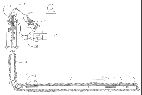
[00151 FIG. 1 is a schematic view showing a downhole assembly containing an
anti-stall
tool according to principles of this invention.
[00161 FIG. 2 shows a cross-sectional view of one embodiment of a hydraulic-
operated
anti- stall tool.
[00171 FIG. 3 is an elevational view showing a further embodiment of an anti-
stall tool.
[00181 FIG. 4 is a cross-sectional view showing the anti-stall tool of FIG. 3
along with a
-4c-
CA 02714899 2012-05-29
schematic view of an improved controller.
DETAILED DESCRIPTION
[00191 FIG. 1 is a schematic diagram illustrating a coiled tubing drilling
system 10 for
drilling a well bore in an underground formation 12. The coiled tubing
drilling system can
include a coiled tubing reel 14, a gooseneck tubing guide 16, a tubing
injector 18, a coiled
tubing 20, a coiled tubing connector 21, and a drill bit 22 at the bottom of
the well bore.
FIG. 1 also shows a control cab 24, a power pack 26, and an alignment of other
BHA tools
at 27. A tractor (not shown), such as that described in U.S. Pat. No.
7,343,982, may be used
to move downhole equipment within the bore. During drilling, the downhole
equipment
includes a downhole motor 28, such as a positive displacement motor (PDM), for
rotating
the drill bit. An anti-stall tool (AST) 30, according to principles of this
invention, is
positioned near the bottom of the coiled tubing, upstream from the downhole
motor and the
drill bit. In one embodiment, hydraulic back pressure produced within the
coiled tubing is
measured at the surface. Torque produced at the drill bit during drilling
operations is directly
related to back-pressure. As a result, hydraulic back-pressure measurements
can be sensed
and used as inputs to a hydraulic control valve system contained in the anti-
stall tool.
[00201 The anti-stall tool 30 incorporates use of a series of hydraulic
cylinders and as
few as three pressure-actuated valves to control the applied weight-on-bit
(WOB) while
drilling. This tool will virtually create a real time, downhole motor pressure
sensor that will
alter the WOB to maintain a relatively constant drilling rate of penetration
and provide
feedback to the coiled tubing operator to adjust coiled tubing injector rates
to match the
PDM pressure.
[00211 The invention uses the working pressure range of the downhole positive
displacement motor 28 to alter the WOB if the downhole pressure surpasses
either end of the
working range. During drilling operations, the AST controls WOB through the
use of three
distinct operations:
- 5-
CA 02714899 2010-06-18
WO 2009/089187 PCT/US2009/030165
active WOB, passive WOB and reverse.
[0022] FIG. 2 illustrates one embodiment of the anti-stall tool 30 which
includes a series of
axially aligned hydraulic cylinders with separate pistons that define piston
areas Al and A2, A3A
and A3B, and A3C and A3D. The torque section of the tool is shown at 35. FIG.
2 also
schematically shows a controller 34 contained in the anti-stall tool. The
controller includes a
pressure reducing valve 36, a reverser valve 38, and a vent valve 40.
Hydraulic control fluid passes
through a filter 42.
[0023] In the description to follow, specific operating pressure set points or
values are related
to operative ranges for coiled tubing equipment. Use of the anti-stall tool in
rotary drilling
operations, for example, would involve use of different operating pressure
ranges or control valve
set points.
[0024] The first stage of the hydraulic anti-stall tool is activated when the
unloaded PDM
produces low downhole pressures. For example, if the PDM creates a back
pressure of 200 psi
(adjustable to specific motor requirements), the anti-stall tool will be in
the active WOB stage.
This causes pressure to be supplied to all pistons that will produce a force
in the downhole
direction (Al, A3A and possibly A3C). As the WOB is applied, the normal
reaction is for the
PDM to generate more pressure. As the anti-stall tool senses the increase in
pressure to 250 psi
(adjustable to specific motor requirements), the pressure reducing valve 36
will shut off additional
flow to the pistons and hydraulically lock the pistons in the passive WOB
stage.
[0025] In the passive WOB stage, the anti-stall tool transfers the force from
the tubing to the
bit. The tool is acting as a rigid member and is monitoring the PDM back-
pressure. The pressure
reducing valve 36 is closed and is sealing the fluid in the pistons (A3A and
possibly A3C) that
produce a force in the downhole direction. All of the resultant pressure from
the WOB will be
contained in the sealed piston volumes.
[0026] During the final stage of the anti-stall tool, the back pressure due to
high torque in the
-6-
CA 02714899 2010-06-18
WO 2009/089187 PCT/US2009/030165
PDM triggers the reverser valve 38 and vent valve 40 to reduce WOB. Once the
back pressure
reaches 1,000 psi (adjustable to specific motor requirements), the reverser
valve 38 switches the
flow of fluid to the pistons that produce force in the uphole direction (A2,
A3B, A3D). At the same
time, the vent valve 40 vents the opposite side of those pistons. This allows
the tool to travel
uphole, reducing WOB and thereby reducing the PDM back pressure. As the PDM
back pressure
falls below the reverser valve setting (including hysteresis) the reverser
valve 38 will switch back
to its original position.
[0027] The anti-stall tool is designed to be in the fully expanded position at
low pressures.
This bias allows the tool to have the full length of stroke available to
retract as much as needed
until the PDM back-pressure reduces below the lower limit of the vent valve.
The anti-stall tool
will then try to fully expand, but the pressure may rise to the pressure
control valve setting or
higher and limit the expansion. Therefore, the long stroke length will allow
several retraction steps
before the stroke length is used up. The coiled tubing operator can adjust the
input speed of the
coiled tubing into the hole to prevent the anti-stall tool from fully
retracting. The operator will see
a change in pump pressure with each retraction to signal the need to reduce
the coiled tubing input
speed.
[0028] The anti-stall tool operates as an open loop system. Drilling fluid
from the surface is
pumped down the bore in the tubing through the tool, to the motor for rotating
the drill bit. Most of
the fluid flow in the system is used for driving the drill bit. A small amount
of the fluid is used for
the controller and is jetted out to the sides and into the annulus during use.
[0029] The anti-stall tool includes splines in a torque section 44 which
contains an outer spline
housing and splines contained internally on the piston housing. The splines
allow the BHA to
maintain its orientation relative to the motor and drill bit, without
undesired twisting. The splines
allow the tool to be used with a steerable BHA. Steerable BHAs can be
controlled to drill the hole
to a desired location, while changing the direction of the hole while drilling
to achieve this goal.
-7-
CA 02714899 2010-06-18
WO 2009/089187 PCT/US2009/030165
I
The splines allow the PDM and bit to maintain alignment with the orienting
tools that would be
uphole of the anti-stall tool. The torque load is transferred from the PDM
across the outermost
housings and across the spline of the anti-stall tool to the tools uphole of
the anti-stall tool. The
inner shafts do not see direct loading due to torque. The spline section
functions in both the
expansion and retraction of the anti-stall tool.
[0030] FIGS. 3 and 4 show an improved anti-stall tool 30' which produces a
three-stage
controlled translational motion to the drill bit that increases drilling
efficiency.
[0031] This illustrated embodiment includes a series of axially aligned
hydraulic cylinders with
pistons that cooperate to form piston areas S1, Al and A2, and A3A and A3B.
The torque section
of the tool is shown at 44 along with a hydraulic controller contained in the
anti-stall tool and
shown schematically at 46. The controller includes a pressure control valve
48, a pilot valve 50, a
sequence valve 52, and a vent valve 54. A filter for the hydraulic controller
is shown at 56.
[0032] In one embodiment, the controller has the three stages of operation:
(1) active, (2)
passive, and (3) retraction. The control valves contained in the controller
area of the tool are shown
schematically in FIG. 4: pressure lines are shown as solid lines, pilot lines
are shown as dashed
lines, and exhaust lines are shown in dotted lines. In the following
description, the pressure ranges
are used as examples only; they are adjustable to specific motor requirements.
[0033] The active stage applies downward force to the drill bit based on motor
back-pressure
from the positive displacement motor. If pressure is less than 400 psi, for
example, the hydraulic
pistons apply a downward force which generates more PDM back-pressure. The
vent valve 54 of
the controller is open and supplies a pilot signal to the pilot valve 50. If
pressure reaches 400 psi,
the vent valve 54 closes and vents the pilot line for the pilot valve 50. But
the detented pilot valve
stays in position, and the PDM back-pressure is sensed by the pressure control
valve 48. The
pistons apply the downward force until sensed downhole pressure reaches 650
psi, for example,
which represents a desired working pressure.
-8-
CA 02714899 2010-06-18
WO 2009/089187 PCT/US2009/030165
1
[0034] The pressure control valve then. switches the anti-stall tool to the
passive mode when
sensed pressure reaches the desired drilling pressure of 650 psi, for example.
Here the pressure
control valve 48 shuts off flow to the pistons and hydraulically locks the
pistons in the passive
WOB mode. The pressure control valve 48 is closed and no pressure is sent to
the pistons. The
pistons are sealed, and existing force is transferred to the drill bit. Motor
pressure is not increased.
Downhole pressure continues to be monitored in the passive mode via the vent
valve 54 and
sequence valve 52, which monitor pressure change in the coiled tubing. The
passive state
continues until sensed back-pressure reaches 800 psi, for example.
[0035] Once downhole pressure reaches the 800 psi level, the anti-stall tool
switches to the
reverse mode. That is, if torque in the PDM increases, it causes an increase
in back-pressure.
Motor stall is prevented by sensing and reacting to back pressure at a level
below motor stall, e.g.,
800 psi, or other pressure below that at which stall can occur.
[0036] When sensed pressure reaches 800 psi, the normally-closed sequence
valve 52 is
opened, sending a pilot signal to the pilot valve 50 which reverses flow of
hydraulic fluid to the
pistons to produce a force in the uphole direction, to reduce WOB.
[0037] As back pressure falls below 800 psi, the pilot signal from the
sequence valve 52 to the
pilot valve 50 is closed. The sequence valve 52 vents the pilot signal, and
this continues until
sensed PDM pressure falls to 400 psi, where the vent valve 54 opens and sends
a pilot signal to the
pilot valve 50 to shift back to the active mode, by supplying fluid pressure
to the pistons in the
forward direction, to apply downward force to increase WOB.
[0038] Thus, in this embodiment, the tool is normally controlled to apply WOB
when drilling
at pressures within a desired wide range of pressures. These can be from 400
to 800 psi, for
example. When reaching a preset anti-stall pressure, such as 800 psi, which
would be a safe level
below the pressure at which stall actually occurs, the tool is reversed and
does not resume applying
WOB over a preset wide range of pressure drop, before resuming active WOB
operations. This
-9-
CA 02714899 2010-06-18
WO 2009/089187 PCT/US2009/030165
wide range of pressure drop can be from about 200 to about 2,000 psi. In the
illustrated
embodiment, the range of pressure drop is 400 psi (from 800 to 400 psi),
before WOB is resumed.
[0039] The tool applies WOB during the desired wide range of operating
pressures via two
stages, one stage where pressure is increasing up to a set desired operating
pressure, for example
650 psi, and then switches to a second-stage locked position at that pressure
and higher up until an
anti-stall limit, of say 800 psi is reached, for reversing flow to the pistons
and lifting the drill bit.
[0040] A key feature of the anti-stall tool is the single input necessary for
the tool to operate.
The tool need only sense and respond to the back-pressure created by the PDM.
Stated another
way, the anti-stall tool operates on constant (although adjustable) working
pressure set points. The
fixed set points can be fine-tuned to control, the thresholds at which the
control valves open and
close, and as a result, drill bit penetration rate is more uniform.
[00411 An alternate embodiment of the invention comprises a two-phase anti-
stall method for
controlling drilling operations in a downhole assembly, which includes the
tubing that extends
downhole, the drill bit carried on the tubing, the positive displacement motor
(PDM) for rotating
the drill bit, and the anti-stall tool adjacent the PDM. This method comprises
sensing pressure in
the PDM, providing a range of operating pressures for the PDM defined by high
and low limits of
operating pressures, and operating the anti-stall tool in: (1) an active stage
increasing WOB forces
in the downhole direction when the low limit of operating pressure is sensed,
and. (2) a reverse
stage providing a force in the reverse direction, reducing the WOB, when the
high limit of
operating pressure is sensed.
[00421 This two-phase anti-stall method can be accomplished by adjusting the
setting of the
sequence valve 52 equal to or lower than the pressure control valve 48, but
still above the setting of
the vent valve 54.
[00431 The anti-stall tool also can be operated by the two-phase method,
combined with a
passive range that operates (as described above) between a small range of
pressure settings.
_10-
CA 02714899 2012-05-29
[00441 Different orifice adjustments can be used to control the speed at which
the tool
responds. In FIG. 2, the orifice is not shown. The orifice can be on the
exhaust of the
reverser valve 38.
[00451 Although the schematic in FIG. 4 depicts a single orifice 55, those
skilled in the
art would understand that the two-position/four-way valve contains two exhaust
ports. Each
of the ports vents a different piston area, either the piston area to produce
downhole force
(expand) or uphole force (retract). Using the high and low limits of the
operating pressures,
the orifice sizes can be calculated to restrict the volumetric flow rate of
fluid exhausted
through the valve and thereby control the speed at which the tool expands or
retracts. The
expansion and retraction of the tool can be controlled individually by
different orifice sizes.
[00461 As an alternative, WOB can be controlled by a combination of control
valve
settings and adjustments to orifice sizes.
100471 EXAMPLE
The following specification illustrate one embodiment of the anti-stall tool:
Description Characteristic
Tool OD 3.00 in
Tool ID .75 in
Length - Expanded 8.1 ft
Length - Collapsed 7.4 ft
Stroke 9 in
Max Temp 300 OF
Tensile Strength 50,000 lbs
Max Motor Torque 2,000 ft-lbs
Max Dog Leg 25 / 100 ft
Tool Joint 2 3/8 PAC
The design is flexible in that the pressure settings and orifice size may be
changed to fine-
tune the tool. If a much larger WOB is needed, then the shaft can be replaced
to allow
installation
-11-
CA 02714899 2010-06-18
WO 2009/089187 PCT/US2009/030165
of additional pistons.
# of Pistons Total Downhole Area Pressure Control Max WOB from AST
(sq. in.) Valve Setting (psi) (lbs)
1 4.8 650 3,055
2 7.9 650 5,135
3 11.0 650 7,150
[0048] The anti-stall tool cylinders and valves may be manufactured from
various corrosion-
resistant materials including tungsten carbide, Inconel, high strength nickel
alloyed steel such as
MP35, beryllium-copper, and the like.
[0049] Examples of improvements provided by the anti-stall tool are:
(1) Active WOB: The tool will attempt reset into the fully extended position
when the pressure
falls below 650 psi. If a motor stall has occurred and the AST has pulled the
bit off bottom,
the Active WOB stage will produce a minimum WOB and thrust the bit downhole
until the
PDM pressure exceeds 650 psi.
(2) Passive WOB: Shuts off the Active WOB stage and allows the coiled tubing
to transfer
WOB to the bit. Prevents excessive WOB that can be developed as PDM pressure
rises and
acts on the pistons producing force downhole.
(3) Reverse: Reduces WOB to prevent motor stalls.
(4) Torque section will transfer torque through the AST into the coiled
tubing.
[0050] A downhole tool that monitors motor pressure and sharply reduces the
occurrence of
motor stalls will increase the overall drilling efficiency by:
(1) Increasing the average rate of penetration. This is achieved reducing the
occurrences of
pulling off bottom for motor stalls.
(2) Decreasing the damage to PDMs through repeated motor stalls, thereby
decreasing
occurrence of downhole failure.
(3) Decreasing the fatigue cycles on the coiled tubing. The increases the
number of wells a
-12-
CA 02714899 2010-06-18
WO 2009/089187 PCT/US2009/030165
coiled tubing string can service.
[00511 By achieving a more efficient drilling operation, the operators can
substantially increase
the cost savings of drilling a well.
[00521 Although the invention has been described in connection with oil well
drilling and use
with a coiled tubing, the invention has other applications, including: jointed
pipe, or rotary drilling;
in operations besides drilling where it is useful to retract a tool at high
pressures; or where
adjustments to the drill bit are made to keep contact with the formation or to
pick up the bit
completely off the formation. Although the invention has been described with
reference to a drill
bit used in drilling oil wells in underground formations, the invention also
may be used with other
pressure-inducing tools such as high pressure jetting tools.
20
-13-