Note: Descriptions are shown in the official language in which they were submitted.
CA 02715224 2010-08-12
WO 2009/100861 PCT/EP2009/000850
1
LOUVER ROTATING MECHANISM
The invention relates to a louver rotating mechanism
for louvers of a sectional covering for architectural
openings. The rotating mechanism thereby is adapted to
rotate the louvers between an open position and a closed
position. In the open position, the louvers are in
generally parallel planes, and in the closed position, the
louvers are generally in a common plane.
Such a louver rotating mechanism is known from
European patent EP 369068. While this louver rotating
mechanism is reasonably efficient in sectional coverings
for architectural openings it also relies on the use of
ladder cords or cables for the support and movement of the
slats. In certain applications and environments there has
developed an interest in more sturdy constructional
arrangements that can cope with larger architectural
openings or those in particularly hostile environments.
Accordingly it is an object of the present invention
to propose an improved actuating system for a folding panel
assembly that is less susceptible to contamination, but
which can still be unobtrusively incorporated in the
actuating system. In a more general sense it is thus an
object of the invention to overcome or ameliorate at least
one of the disadvantages of the prior art. It is also an
object of the present invention to provide alternative
structures which are less cumbersome in assembly and
operation and which moreover can be made relatively
inexpensively. Alternatively it is an object of the
CA 02715224 2010-08-12
WO 2009/100861 PCT/EP2009/000850
2
invention to at least provide the public with a useful
choice.
To this end the invention provides a louver rotating
mechanism for louvers of a sectional covering for
architectural openings, the rotating mechanism being
adapted to rotate the louvers between an open position, in
which the louvers are in generally parallel planes, and a
closed position, in which the louvers are generally in a
common plane, wherein the rotating mechanism includes a
slot and gate system. Such an arrangement eliminates the
need for relatively vulnerable ladder cords for initiating
rotational movement of the louvers.
Advantageously the louver rotating system according to
the invention can include in its slot and gate system any
appropriate combination of: a guiding track; a plurality of
louver holders; a slotted flange on the guiding track; a
plurality of transverse slots opening into a free edge of
the slotted flange; a tilt arm on each of the louver
holders; and a gate slider movably associated with the
slotted flange to open and close the transverse slots to
one or more of the tilt arms.
The louver rotating mechanism may include a guiding
track and a plurality of louver holders for holding
respective louvers, each louver holder movable along the
guiding track and pivotable so as to rotate a respective
louver between the open position and the closed position.
A mechanism is preferably provided for moving the louver
holders along the track between retracted and extended
positions. The slot and gate system may include a
plurality of slots spaced along the guiding track, each
slot extending substantially transversely to the guiding
CA 02715224 2010-08-12
WO 2009/100861 PCT/EP2009/000850
3
track. Each louver holder may include a respective tilt
arm engageable in a respective slot such that movement of
each one of the louver holders, when the tilt arm of the
one of the louver holders is engaged in a respective slot,
causes the one of the louver holders to pivot so as to
rotate a respective louver between the open position and
the closed position. The slot and gate system may include
a gate system for closing the slots so as to prevent tilt
arms from engaging in the slots and for opening the slots
to allow the tilt arms to engage in the slots.
In this way, the gate system can be considered to
include a plurality of respective gates for opening and
closing the respective slots.
The gates can be controlled individually or in groups.
Preferably, each respective gate is movable relative
to the guiding track between a blocking position in which
the respective slot is closed and an access position in
which the respective slot is open.
In this way, each slot may be conveniently opened or
closed so as to allow a respective tilt arm to engage in
that slot and to enable rotation of a respective louver
holder.
Although gates may be operated individually,
preferably, the gate system includes a gate slider having a
plurality of the respective gates for opening and closing
respective slots. The gate slider may be movable relative
to the guiding track between the blocking position in which
the slots are closed and the access position in which the
slots are open. In this way, it is only necessary to move
the slider in order to open or close simultaneously a
plurality of gates and slots.
CA 02715224 2010-08-12
WO 2009/100861 PCT/EP2009/000850
4
The gate slider may be movable in the length direction
of the guiding track.
With this arrangement, the gate slider may define a
plurality of cavities spaced in accordance with the
successive transverse slots and movable between the
blocking position in which none of the cavities is in
register with a transverse slot and the access position in
which all of the cavities are in register with a respective
transverse slot.
In this way, the gate slider need merely be moved
longitudinally with respect to the guiding track in order
to open or close the gates.
The gate slider may alternatively be movable
transversely to the length of the guiding track.
With this embodiment, the gate slider may include a
plurality of gate recesses which confront respective slots,
those gate recesses including respective barrier wall
portions for blocking access to the respect slots.
The gate system may include a longitudinal slider
movable in the length direction of the guiding track. The
gate slider is preferably connected to the longitudinal
slider such that movement of the longitudinal slider in the
length direction of the guiding track is converted into
transverse movement of the gate slider.
In this way, it is possible to move the gates between
open and closed positions merely by moving the longitudinal
slider lengthwise with respect to the guiding track.
Preferably, the gate slider connects with the
longitudinal slider by sliding pins which engage in
conversion tracks having respective slanted end portions.
CA 02715224 2010-08-12
WO 2009/100861 PCT/EP2009/000850
The conversion tracks can be formed in the
longitudinal slider and the sliding pins formed in the gate
slider or the conversion tracks can be formed in the gate
slider and the sliding pins formed in the longitudinal
5 slider. Irrespective, by virtue of the slanted portions of
the conversion tracks, longitudinal movement of the
longitudinal slider is converted into transverse movement
of the gate slider so as to open or close the gates/slots.
Preferably, the gate slider is movable transversely
between a blocking portion in which the slots are closed an
an access portion in which the slots are open.
The gate recesses may include respective transverse
recess parts extending behind the respective barrier wall
portions. The transverse recess parts are blocked by
respective barrier wall portions when the gate recesses are
in the blocking position.
The gate recesses may further include respective
longitudinal recess parts extending longitudinally from
behind respective barrier wall portions. In this way, when
the gate slider is in the access position, the respective
barrier wall portions are positioned transversely outwardly
from the slots so as to expose and provide access to the
respective transverse recess parts via the respective
longitudinal recess parts.
In this way, with the gate slider in the blocking
position, the barrier wall portions overlap with respective
slots such that tilt arms are not able to access respective
transverse recess parts. However, when the gate slider is
moved transversely to the access position, the longitudinal
recess parts are also moved transversely outwardly and
become available to tilt arms before they reach (as they
CA 02715224 2010-08-12
WO 2009/100861 PCT/EP2009/000850
6
travel longitudinally) the respective barrier wall
portions. In that state, the barrier wall portions are
positioned outwardly from the slots such that tilt arms are
able to follow the longitudinal recess parts into the
transverse recess parts.
The guiding track may include a re-entrant flange
defining the transfer slots.
In this way, when the gate slider moves in the length
direction of the guiding track, the cavities are moved into
or out of alignment with the transverse slots defined by
the re-entrant flange. Alternatively, when the gate slider
is movable transversely to the length of the guiding track,
the barrier wall portions are moved transversely outwardly
from under the re-entrant flange so as to expose the
transfer slots by means of the longitudinal recess parts.
Rather than use a re-entrant flange defining the
transverse slots, it is possible to provide a slot and gate
system including a guide wall extending alongside the
guiding track with a plurality of spaced apart openings
defined in the guide wall. A plurality of respective
slider units may be arranged in respective openings and the
plurality of transverse slots may be provided in respective
slider units.
Preferably, the slider units are movable transversely
between a blocking position in which the slots are closed
and an access position in which the slots are open.
Each slider unit may include a respective barrier wall
portion arranged to block access to a respective opening
when the respective slider unit is in the blocking
position.
CA 02715224 2010-08-12
WO 2009/100861 PCT/EP2009/000850
7
By blocking the respective opening, the respective
tilt arms may be prevented from accessing the transverse
slots in the slider units.
In this respect, the slots are preferably provided
behind the respective barrier wall portions. When the
slider units are in the access position, the respective
barrier wall portions are positioned transversely outwardly
from the guide wall so as to expose and provide access to
the respective slots for the tilt arms.
Preferably, the slider units are movable in the length
direction of the guide track at the same time as moving
transversely along the length of the guide track. In this
way, in the access position, the respective barrier wall
portions are displaced longitudinally with respect to the
openings so as to expose the respective slots in the slider
units.
Preferably, the slider units are connected relative to
the guide wall by sliding pins engaging in conversion
tracks having respective slanted portions.
The slider units may be provided with sliding pins
with conversion tracks provided on a support structure or,
alternatively, the slider units may be provided with
conversion tracks with the sliding pins formed on the
support structure.
Preferably, the sliding pins take the form of bushes.
The slider units may be provided on the gate slider
with the gate slider movable in the length direction of the
guiding track. The gate slider is thus also movable both
transversely to and along the length of the guiding track.
In this way, all of the slider units on the gate
slider may be moved together.
CA 02715224 2010-08-12
WO 2009/100861 PCT/EP2009/000850
8
The slot and gate system may further include a coupler
block movable along the guiding track to operate the gate
system to open the slots.
Preferably, the plurality of louver holders are
arranged as an array along the guiding track and include an
extended-most louver holder at the distal end of the array.
The extended most louver holder may be arranged to abut and
move the coupling block to operate the gate system.
Translatory movement of the coupling block in the
length direction of the guiding track is arranged to move
the gate slider. When the gate slider is movable in the
longitudinal direction, then the coupling block is arranged
to move the gate slider in the same direction. Where the
gate slider moves only transversely and a longitudinal
slider is provided, then the coupling block may be arranged
to move the longitudinal slider in the same direction.
Where slider units are used, preferably a detachable
attachment is provided between the gate slider and the
coupling block for attaching the gate slider and the
coupling block. The detachable attachment may be arranged
to detach the gate slider from the coupling block when the
slider units are in the access position so as to allow
additional longitudinal movement of the coupling block.
In this way, the louver holders may continue to move
longitudinally such that they are rotated to their closed
position.
Rather than use the coupling block arrangement, it is
also possible to provide a separate motive means, such as a
electric motor, for the gate slider or longitudinal slider.
Similarly, individual gates, for instance the gate sliders,
could be moved independently.
CA 02715224 2010-08-12
WO 2009/100861 PCT/EP2009/000850
9
Preferably, the louver holders are biased towards the
closed position. This may be achieved by one or more of a
torsion spring and gravity.
Preferably, each tilt arm includes a respective
follower pin engageable in a respective slot.
Preferably, the mechanism further includes a plurality
of louver carrier trucks movable along the guiding track.
Each louver holder may be pivotably journaled on a
respective louver carrier truck.
Further advantageous aspects of the invention will
become clear from the appended description of preferred
embodiments.
The invention will now be described in reference to
the accompanying drawings, in which:
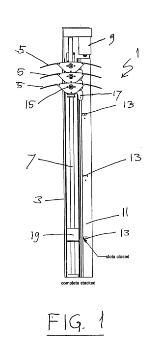
Figure 1 is a side view of a louver guiding mechanism
incorporating a louver rotating mechanism according to the
invention;
Figure 2 is a side view similar to figure 1, but with
the louver holders in a lowered position;
Figure 3 is a side view similar to figure 2, but with
the louver holders in an end position ready to be rotated;
Figure 4 is a side view similar to figure 3, but with
the louver holders partially rotated;
Figure 5 is a side view similar to figure 4, but with
the louver holders fully rotated;
Figure 6A is a perspective view of a louver guiding
mechanism with a louver rotating mechanism according to the
invention;
Figure 6B is a gate slider isolated from the mechanism
of figure 6B;
CA 02715224 2010-08-12
WO 2009/100861 PCT/EP2009/000850
Figure 7 is a partial exploded view of the louver
guiding and rotating mechanism of figure 6A;
Figure 8 is a partial perspective view of two stacked
louver holders and their associated carrier trucks;
5 Figure 9 is a partial perspective view of a lower end
of one of the louver holder and carrier truck and a gate
slider coupler block;
Figure 10 is an exploded view of a louver guiding and
rotating mechanism according to an alternative embodiment
10 of the invention;
Figure 11A is a front elevation of a gate slider of
the embodiment of fig. 10;
Figure 11B is a rear elevation of the gate slider of
figure 11A;
Figure 12A is a partial cross section from the front
side of the louver guiding mechanism of figure 10;
Figure 12B is a partial cross section from a rear side
of the louver guiding mechanism of figure 10;
Figure 13A is a partial cross section similar to fig.
12A with the transverse slots in a half open position'
Figure 13B is a partial cross section similar to fig.
12B with the transverse slots in a half open position.
Figure 14A is a partial cross section similar to fig.
12A with the transverse slots fully open at the start of
louver tilting.
Figure 14B is a partial cross section similar to fig.
12B with the transverse slots fully open at the start of
louver tilting.
Figure 15A is a partial cross section similar to fig.
12A with the transverse slots fully open and halfway
through tilting of the louvers;
CA 02715224 2010-08-12
WO 2009/100861 PCT/EP2009/000850
11
Figure 15B is a partial cross section similar to fig.
12B with the transverse slots fully open and halfway
through tilting of the louvers;
Figures.16(A) to (C) illustrate schematically one gate
and slot of the alternative embodiment of Figures 10 to 15;
Figure 17 is an exploded view of a lower guiding and
rotating mechanism according to yet another embodiment of
the invention;
Figure 18(A) to (C) illustrate schematically one gate
and slot of the embodiment of Figure 17;
Figure 19(A) to (D) illustrate operation of the
embodiment of Figure 17;
Figure 20 is an exploded view of part of the
embodiment of Figure 17; and
Figure 21 illustrates a variation to the embodiment of
Figure 17 using a separate motor for the gate system.
In fig. 1 a louver guiding and rotating mechanism 1 is
shown that includes a side guiding channel or track 3.
Guided by the guiding channel 3 are a plurality of louver
or slat holders 5, which are shown in a stacked position at
the top of the side guiding channel 3. Also included in the
guide channel 3 may be a mechanism for lowering the louver
holders 5. The mechanism for lowering the louver holders 5
is not critical to the invention and may comprise a screw
spindle 7 as taught by US 2.179,882, driven by electric
motor 9. However, this mechanism for lowering and raising
the louver holders can be replaced by a mechanism as taught
by EP 369 068, with equally good results. Accordingly a
suitable mechanism for moving the louver holders between a
retracted and extended position will be known to the
skilled person and not require any detailed description in
CA 02715224 2010-08-12
WO 2009/100861 PCT/EP2009/000850
12
connection with the present invention. The side guiding
channel 3 further has a re-entrant front flange 11 with
regularly spaced transverse slots 13 opening into a free
edge of the re-entrant front flange 11. Each louver holder
5 has a pivot journal 15 and a tilt or pivot arm 17.
Moving now to fig. 2 and 3, the louver holders 5 are
shown in an extended, and a fully extended position
respectively. In fig. 2 the tilt arms 17 are each
approaching a respective one of the transverse slots 13 and
in fig. 3 are each aligned with a respective slot 13.
It is also seen in fig. 1 to 5 that the side guiding
channel 3 near its lower end has a gate slider coupling
block 19. In the position of fig. 2 the lowermost louver
holder 5 is just starting to abut the coupling block 19. In
the position of fig. 3 the lowermost louver holder 5 has
moved the coupling block 19 with respect to the side
guiding channel 3 in a downward direction. A mechanism to
be described herein below is operatively connected to the
coupling block 19 to make the transverse slots 13
accessible to the tilting arms 17. Fig. 4 and 5 show how
continued movement of the louver holders 5 in a downward
direction along the guide channel 3 allows the tilt arms 17
each to become engaged in the respective transverse slot
13, which causes the louver holders 5 to pivot about their
pivot journals 15. In fig. 5 the fully tilted end position
for the louver holders 5 is shown.
Figure 6 shows a first embodiment of louver rotating
mechanism 101 having a guiding channel 103 and louver
holders 105. The guiding channel 103 has a re-entrant
flange 111 defining transverse slots 113 opening into a
free and thereof. The louver holders 105 are each pivotally
CA 02715224 2010-08-12
WO 2009/100861 PCT/EP2009/000850
13
journalled on a respective louver carrier truck 121, one of
which is shown without louver holder for clarity. Each
engagement with a respective one of the transverse slots
113. Also shown in Figure 6A is a gate slider coupling
block 119, which operates a gate slider, or slide gate,
123, shown separate in Figure 6B.
In Figure 7 one of the louver holders 105 is shown in
an exploded arrangement. The louver carrier truck, or
louver truck, 121 has a central bore 125 which accepts
journal pin 127. Surrounding the journal pin 127 is a
helically wound torsion spring 129. The torsion spring 129
has an axially extending tang 131 and a radially extending
tang 133 each on a respective opposite end thereof. The
axially extending tang 131 is adapted to engage into a hole
135 on the carrier truck 121. A selection of angularly
spaced holes 135 may be provided to adjust the torsional
torque excerted by torsion spring 129 on the louver holder
105 through its radially extending tang 133. The function
of torsion spring 129 is to resiliently bias the louver
holders 105 into their tilted positions to ensure proper
engagement of the lift arms 117 (Fig. 6A) into the
transverse slots 113. An opposite end of journal pin 127 is
received in a bearing block 137, and will be retained
therein by a locking ring 139 engaging a circumferential
groove 141 on one end of the journal pin 127. The bearing
block 137 is received in a cavity 143 formed in a louver
holder body 145. The torsion spring 129 is accommodated in
a barrel cavity 147, also formed in the holder body 145.
The assembly of the louver holder 105 is completed by a
holder body inlay 149.
CA 02715224 2010-08-12
WO 2009/100861 PCT/EP2009/000850
14
As best seen in Figure 8 the louver holders 105 and
carrier trucks 121 are stackable. In the holder body 145
and holder body inlay 149 a recess 151 is formed to
accommodate the tilt arms 117 when the louver holders 105
are in a stacked arrangement as shown in Fig. 8. It is also
seen in Figure 8 that the tilt arm 117 can have a follower
pin 153, which may be provided as a roller to reduce
friction when engaged against the re-entrant flange 111
(Figs. 6 and 7), or when engaged in one of the transverse
slots 113.
Figure 9 shows the arrangement of a lower most louver
holder 105 and carrier truck 121 with respect to the gate
slider coupling block 119. The lower most carrier truck 121
is provided with a downwardly extending pin 155, which has
a detent recess 157. The gate slider coupling block 119 is
adapted to receive the downwardly extending pin 155 of the
carrier truck 121. A locking ball 161 movably retained in a
transverse bore in coupling block 119 when received in the
detent recess 157 of the extending pin 155 will lock the
lower most carrier truck 121 to the coupling block 119, for
movement in unison therewith.
Reverting now to Figure 6, the coupling block 119 is
operatively connected to gate slider 123, so that
translatory movement of the coupling block 119 with respect
to the length direction of the guiding channel 103 will
move the gate slider 123 in the same direction. As seen in
Figure 6 the gate slider 123 is provided with a plurality
of cavities 165, which are spaced in accordance with the
successive transverse slots 113 on the flange 111 of the
guiding channel 103. Movement of the gate slider coupling
block 119 is limited between a first position, in which
CA 02715224 2010-08-12
WO 2009/100861 PCT/EP2009/000850
none of the cavities 165 is in register with a transverse
slot 113, and a second position, in which all of the
cavities 165 are in register with a relevant one of the
transverse slots 113.
5 In operation the louver holders 105 may be in a
stacked position as shown in Figure 1. When from this
position the louver holders are lowered by an appropriate
lowering mechanism (such as those disclosed by US 2,179,882
or EP 369 068), the lowermost carrier truck 121 will be
10 advanced through the guide channel 103 in the direction of
the gate slider coupling block 119. The other carrier
trucks 121 will be advanced either directly by the lowering
mechanism (as in the case of US 2,179,882) or indirectly by
the lowermost carrier truck (as in the case of EP 369 068).
15 During this movement the tilt arms 117 of the louver
holders 105 will be biased by torsion springs 129 against
the free edge of re-entrant flange 111. With the carrier
trucks 121 thus moving from a stacked position in the
direction of the gate slider coupling block 119, the gate
slider 123 (see Figure 6) will have its cavities 165 out of
alignment with the open ends of the transverse slots 113,
so that the follower pins 153 on the tilt arms 117 cannot
enter the transverse slots 113. Towards the end of travel
of the lowermost carrier truck 121 this will abut against
the gate slider coupling block 119. The gate slider 123 is
connected to the coupling block 119 for translatory
movement therewith in the length direction of the side
guiding channel 103. Engagement of the downwardly extending
pin 155 of the lowermost carrier truck 121 with the
coupling block 159 will allow the locking ball 161 to move
inwardly into the detent recess 157, which effectively
CA 02715224 2010-08-12
WO 2009/100861 PCT/EP2009/000850
16
unlocks the coupling block 119 from the guiding channel
103. Continued movement of the lowermost carrier truck 121
will then start to move the coupling block 119 in the same
downward direction and thereby gradually move the cavities
165 of the gate slider 123 into register with the
respective open ends of the transverse slot 113.
Simultaneously the follower pins 153 of the tilt arms will
each engage into a relevant one of the transverse slots
113. This corresponds to the position of the slot holders
shown in Figure 3. Further movement, as allowed by the
coupling block 119, will then enable the louver holders 105
to tilt to any position between horizontal and vertical, as
shown by the examples of Figures 4 and 5. Reverse movement
of the lowermost carrier truck 123 will first take with it
the coupling block 119, by means of the locking ball 161
being engaged with the detent recess 157 of the downwardly
extending pin 155 of the lowermost truck 121. The louver
holders will thereby pivot in a reverse direction from that
shown in Figures 3 to 5, until the coupling block 119
returns to its initial position with the coupling block 119
returned to its initial position, the locking ball 161 can
move outwardly again to lock the coupling block 119 again
to the guiding channel 103, whereby the downwardly
extending pin 155 of the lowermost truck 121 becomes
unlocked and allows all the carrier trucks 121 to move
upwardly, as desired, until the stacked position shown in
Figure 1. In the meantime also the gate slider 123 (Figure
6) will have returned to a position in which it closes the
open ends of the transverse slots 113. While moving along
the guide channel, there is thereby no risk that the
follower pins 153 of the tilt arms 117 become engaged in
CA 02715224 2010-08-12
WO 2009/100861 PCT/EP2009/000850
17
any of the transverse slots 113 they may pass en route to
their stacked position.
In accordance with the invention, the louver
rotating mechanism 101 is made up of various components
acting together to cause louvers or louver holders 105 to
rotate to a closed position when the group of louver
holders 105 is fully extended. Also in accordance with the
invention, the rotating motion may be achieved using the
same motor and transmission of power that stacks the louver
holders 105.
The basic components of the system are; the track 103
and carrier trucks 121, the torsion spring loaded louver
holders 105, the slot and slide gate operating system, and
the ball transfer locking coupler block 119.
Even though the described embodiment has been built to
rotate the louver holders 105 in the fully extended
position, the mechanism can be modified with the option of
having a separate motor or solenoid actuating the slider
gate 123 so the louvers or louver holders 105 could be
rotated at any position in between fully extended and fully
retracted. Furthermore, the slider gate 123 can be
constructed in two or more independently actuated segments
so that regions of louvers within a louver panel may be
rotated open while the other regions remain closed. This is
possible because each louver holder 105 rotates
independently under its own spring 129 load. However, it
should be noted that if the louvers are rotated in any
position other than at full extension a more complex limit
switching device would be needed for the motor.
The louver holder 105 can be made up of two halves
that mate so the spring and bushing system may be
CA 02715224 2010-08-12
WO 2009/100861 PCT/EP2009/000850
18
assembled. This split design could also help in the
replacement of louvers in the system. The spring 129 and
shaft 127 need to have bearing surfaces on both ends of the
torsion spring 129 for smooth friction-free rotation. At
the end of the louver holder 105 is an annular recess which
couples with a protrusion on the main carrier truck 121. On
the opposite end of the torsion spring 129 inside the
louver holder 105 is a bearing block 137. The torsion
spring 129 is designed to add torque so it will bias the
louver holder 105 to the closed position when allowed by
the gate system.
While the described embodiment uses a relatively large
holder 105 for the above stated reason, the same spring
loaded bushing and spring mechanism may be inserted
directly into an extrusion with a narrow end plate and tilt
arm in order to keep the cost down. The described
embodiment was designed as an extrusion, but may in fact be
obtained by any other appropriate shaping technique.
When the torsion spring 129 is twisted, it grows a
little in the coil length so some space is needed in the
barrel cavity housing the spring 129. Additionally, in
order to help it remain engaged in the carrier truck 121,
the torsion spring 129 is designed also to act as a
compression spring 129. Force from this compression
component pushes the tang 131 at the end of the spring 129
into a hole 135 in the carrier truck 121. In the described
embodiment truck body 121 there are four holes 135 for
spring engagement. This allows for some adjustability of
torsion force. The holes 135 are positioned at 90 degrees
increments. The spring 129 is conveniently made from series
302 stainless steel and it is thereby rated for around
CA 02715224 2010-08-12
WO 2009/100861 PCT/EP2009/000850
19
50,000 cycles. By spring-loading the individual louver
holders 105, the entire system is designed to place as
small a torque load on the motor and linkages so as to
require a small motor and to minimize maintenance.
Each louver holder 105 has a tilt arm 117 that
controls the tilting with a follower pin or roller 153. As
the louver truck 121 carries the louver holder 105 up and
down the track 103, the follower 153 rides on the surface
of a slot and gate system. When the gates are closed the
louver holders 105 ride freely up and down the track with
the louvers in the open position. When the bottom louver
carrier truck 121 reaches the bottom of the track 103, it
engages a coupler block 119 which attaches itself to the
louver truck 121 and moves with it. As the coupler block
119 is moved downward it pulls a gate system 123 down and
this opens all the slots 113 allowing every louver follower
153 to slide into its respective slot and thus rotate the
louvers in unison.
When the gates are opened, the follower 153 rolls
around a slot profile 113 designed to move the tilt arm 117
and rotate the louver holders 105. For the current
embodiment there are proposed three basic slot profiles;
simple radius, simple chamfer, and a lobed radius profile.
The profile versions may be swapped for various
applications. It will be good to test each possible
application for smooth transitions and for required torque
on the motor. An extended shaft may further be provided on
a bottom end of the described embodiment to enable testing
with alternate motors or a hand crank.
The coupler block 119 that is connected to the gate
slide 123 engages with the bottom carrier truck 121 and
CA 02715224 2010-08-12
WO 2009/100861 PCT/EP2009/000850
triggers the slide action of the gates. It is an elegantly
simple design that functions very well doing a complex
task. When the bottom louver carrier truck 121 is up away
from the gate slider 123 coupler block 119, the gate slider
5 coupler block 119 is locked in position. This prevents the
gates from opening at the wrong time. As the bottom louver
carrier truck 121 approaches the gate slider coupler block
119, it releases it from its locked position and the
coupler block 119 and louver truck 121 become attached to
10 each other. This is important because when the bottom
louver carrier truck 121 reverses direction, it needs to
cause the gate slider coupler block 119 to close the gates.
The pulling action of the bottom louver carrier truck 121
pulls the gate slider coupler block 119 as reliably as it
15 pushes in the other direction. This is achieved with the
transfer ball and detent system 157, 161.
In reference to Figures 10 to 16 a side guiding
channel or track 203 will be described which uses an
alternative form of slot and gate system. In Figure 10 the
20 components making up the alternative slot and gate system
are shown in an exploded arrangement. The side guiding
channel 203 includes a main profile 275 a gate slider
coupling block 219, a slotted flange 211, a gate slider 223
and a coupling block connector 277. The slot and gate
system of Figures 10 to 15 differs from that described in
reference to Figs. 6 to 9, in that the gate slider 223 is
movable only transversely to the length of the guiding
channel 203, rather than longitudinally thereof.
Accordingly the slot and gate system of Figs. 10 to 15 has
an additional intermediate slider 279, from which sliding
pins 281 project at predetermined locations along its
CA 02715224 2010-08-12
WO 2009/100861 PCT/EP2009/000850
21
length. The sliding pins 281 are for connecting the
intermediate longitudinally sliding slider 279 to the
transversely movable gate slider 223. The gate slider 223
is transversely slidable connected to the slotted flange
211 by means of bushes 283, engaged through transverse
mounting slots 285 in the gate slider 223. Further the gate
slider 223 is provided with a plurality of gate recesses
287, which confront relevant transverse slots 213 in the
flange 211. The intermediate slider 279 is longitudinally
slidable retained to the main profile 275 by means of slide
supports 289. The coupling block connector 277 is attached
to the intermediate slider 279 and connects to the coupling
block 219 through an elongate slot 291 in a wall portion of
the main profile 275.
As respectively shown in Figures 11A en 11B the gate
slider 223 has a front side 293 and a rear side 295. The
front side 293 is provided with the gate recesses 287,
while the mounting slots 285 extend through the gate slider
223 to both sides of the gate slider 223. The rear side 295
is provided with conversion tracks 297, in which the
sliding pins 281 of the intermediate slider 279 are adapted
to engage. The conversion tracks 297 each have a slanted
end portion 297A. It is also shown in Figure 11 that the
gate recesses 287 each have a barrier wall portion 287A.
Referring now to Figures 12 to 15, the operation of
the alternative slot and gate system will be explained.
In Figure l2A the gate slider 223 is shown in its
extreme right hand blocking fully beneath the slotted
flange 211 position, with the barrier wall portions 287A
effectively blocking access to the transverse slots 213.
Although not shown in Figure 12A, the transverse slots 213
CA 02715224 2010-08-12
WO 2009/100861 PCT/EP2009/000850
22
are aligned with the horizontal transverse recess parts of
gate recesses 287. Figure 12B shows the corresponding
position of the gate slider 223 as viewed from the opposite
side (extreme left hand position). The coupling block 219,
in Figures 12A and 12B, is in an extreme top longitudinal
position together with the sliding pins 281. The sliding
pins 281 are thus located in the slanted top portion 297A
of the conversion tracks 297. As a result the gate slider
223, by virtue of the slanted portion 297A of the
conversion tracks 297, has started to move outwardly from
under the slotted flange 211.
Figure 16A illustrates one slot 213 and gate slider
223 in this state.
In Figure 13A the gate slider has started to move
gradually from its position in Figure 12A in the direction
of arrow 301.
In this intermediate position the transverse slots 213
(see Fig. 10) will still be blocked by the barrier wall
portions 287A. This movement is caused, as shown in Figure
13B by the coupling block 219 being moved in a downward
direction by an endmost louver carrier truck (not shown,
but identical to those shown in the embodiment of Figures 6
to 9). Movement of the coupling block 219 in a downward
longitudinal direction causes movement of the sliding pins
281 in the same downward direction. This is so because the
sliding pins 281 move together with the intermediate slider
279 (which is deleted from Figures 12 to 15). Through the
slanted end portion 297A, the vertical longitudinal
movement of the sliding pin 28 will be converted into a
horizontal transverse movement of the gate slider 223 in
the direction of arrow 303.
CA 02715224 2010-08-12
WO 2009/100861 PCT/EP2009/000850
23
Figure 16B illustrates the slot 213 of Figure 16A in
this state.
In Figure 14A the gate slider 223 has reached its
extreme left hand access position by completing its
movement in the direction of arrow 301. As a result the
open end of the gate recesses 287 will now be accessible to
the follower pins 153 (identical to the embodiment of Figs.
6 to 9), which will thus be guided to the horizontal
transverse recess part of the gate recess 287 and be able
to enter the relevant transverse slot 213 (see Figure 10).
Similarly Figure 14B shows from the rear side how the
sliding pins 281 have progresses to the junction between
the slanted end portion 297A and the vertical longitudinal
section of the conversion track 297. Thereby the gate
slider 223 cannot move any further in the direction of
arrow 303.
Figure 16C illustrates the slot 213 of Figures 16A and
B in this state.
As seen in Figures 15A and 15B, further vertical
longitudinal movement of the coupling block 219 and the
sliding pins 281 will have no further effect on the
position of the gate slider 223. However through the
carrier truck 121, connected to the coupling block 219 the
slat holder pivot journals (15 in Figures 1 to 5) will
continue to move in a vertical longitudinal direction. At
the same time the follower pins 153 on the tilt arms 117
(Figs. 6 to 9) are engaged in the transverse slots 213 and
will thus initiate tilting of the louver holders 105 (Figs.
6 to 9).
CA 02715224 2010-08-12
WO 2009/100861 PCT/EP2009/000850
24
An alternative form of slot and gate system is now
described with reference to Figures 17 to 21. Like parts
use similar reference numerals, but in the 400 series.
Figure 17 illustrates a mechanical version of the
embodiment using a guiding track 403 with a gate slider
423. Other similar embodiments are possible using gates
which are separately actuable, individually or together,
for instance with electrical motors or solenoids.
The embodiment of Figure 17 is illustrated with a
cover 500. Although this cover looks similar to the re-
entrant front flange 11, 111, 211 of earlier embodiments,
it does not provide the re-entrant function and is not
necessary for functioning of the invention in this
embodiment. As will be described below, the transfer slots
of this embodiment are provided in slider unit, each
preferably provided as part of the gate slider 423. The
louver tilt mechanism of this embodiment functions
correctly without the cover 500. The cover 500 is provided
only to close the arrangement and protect it against dirt.
As illustrated, the guiding track 403 is provided as a
main track 502, together with a secondary track 504. The
main track 502 thus forms the main portion of the guiding
track of earlier embodiments. It houses the louver carrier
trucks 421 (only one shown in Figure 17) and the spindle
407 which can be rotated to move the louver carrier trucks
421. The spindle 407, although not illustrated, includes
an outer thread for moving the louver carrier trucks 421.
Of course, as with earlier embodiments, any other
appropriate mechanism for moving the louver holders can be
provided.
CA 02715224 2010-08-12
WO 2009/100861 PCT/EP2009/000850
The secondary track 504 runs alongside the main track
502 and, hence, extends in the same longitudinal direction
as the guiding track 403. As illustrated most clearly in
Figures 18(A) to (C), a support wall 506 extends outwardly
5 and transversely from the main track 502. Extending
upwardly from the support wall 506 is a guide wall 508
which extends alongside the guiding track formed by the
main track 502 and defines therebetween the secondary track
504.
10 As illustrated, the guide wall 508 is provided with
spaced apart openings 510 along its length.
A plurality of spaced apart slider units 512 are
provided for respective openings 510. Although the slider
units 512 could be provided individually (for instance
15 actuated by respective solenoid devices), in the
illustrated embodiment, gate slider 423 is provided as an
elongated profile with the spaced apart slider units 512.
Each slider unit 512 includes a gate closing member 514
forming a barrier wall portion 516, a transfer slot 413 and
20 a diagonal mounting slot or conversion track 497.
The gate closing member 514 is shaped generally as a
right-angle trapezium, or in American English trapezoid,
also known as a quadrilateral with two opposite parallel
sides, a right angle and only one slanted side. The gate
25 closing member 514 sticks out from the elongated profile of
the gate slider 423. Its longest or base side forms the
barrier wall portion 516 for closing a respective opening
510 in the guide wall 508 of.the secondary track 504.
As illustrated, behind the barrier wall portion 516,
there is provided a square portion in which the diagonal
conversion track 497 is formed. The conversion track 497
can also be considered to be equivalent to the mounting
CA 02715224 2010-08-12
WO 2009/100861 PCT/EP2009/000850
26
slots 285 of the previous embodiment. However, whereas the
mounting slots 285 of the previous embodiment were arranged
only transversely, the diagonal conversion slot 497 of the
present embodiment extend both transversely and
longitudinally. Similar to the previous embodiment, the
diagonal conversion tracks may be secured to the support
wall 506 by means of bushes or sliding pins 483. As
illustrated, the conversion tracks 497 have the same angle
as the slanted sides 518 of the gate closing members 514
and effectively form extensions thereof.
As mentioned above, the transverse slots of previous
embodiments are formed in respective slider units 512. In
each slider unit 512, the transverse slot 413 is positioned
parallel and adjacent to the right angle side of gate
closing member 514 and the square portion in which the
conversion tracks 497 are formed.
In operation, the plurality of gates of the slot and
gate system are formed by respective openings 510, barrier
wall portions 516 and transverse slots 413. In operation,
the gates may be either closed by the gate slider 423,
partially opened or fully opened. The gates are closed
when the barrier wall portions 516 fill their respective
openings 510 and are positioned in parallel with the guide
wall 508. In this closed position, the gates will force
the follower pins of the tilt arms of louver holders to
travel along the secondary track 504. In this way, the
louver holders are moved along the guiding track 403 such
that they are deployed or stacked.
General operation of the slot and gate system can be
achieved in a manner similar to the embodiments discussed
above. In particular, when a lower or extended-most louver
CA 02715224 2010-08-12
WO 2009/100861 PCT/EP2009/000850
27
holder reaches the coupling block 419 such that its louver
truck 421 abuts the coupling block 419 and connects to it,
further movement of the louver holder and louver truck 421
moves the coupling block 419 and also the gate slider 423
so as to open the gates by means of the slider units 512.
For the present embodiment, a slider connector 477 is
provided to connect the coupling block 419 to the gate
slider 423.
As will be apparent from the description given above,
due to the diagonal orientation of the conversion tracks
497, movement of the gate slider 423 to open the gates will
be both transverse and longitudinal with respect to the
guiding track 403. In particular, the movement is guided
by the bushes or pins 483 in the diagonal mounting slots
forming the conversion tracks 497.
When the gate slider 423 is moved longitudinally by
the coupling block 419 so as to open the gates, the gate
closing member 514 slides longitudinally and transversely
through the opening 510 into the secondary track 504 as
illustrated in Figure 18 (B). When the barrier wall
portion 516 reaches the opposite inner wall of the
secondary track 504, the transverse slot 413 of the slider
unit 512 is positioned in line with the respective opening
510 as illustrated in Figure 18 (C). Hence, the transverse
slot 413 has been opened. Additionally, the gate closing
member 514 acts to block the secondary track 504. A
follower pin of a tilt arm of a louver holder moving along
the secondary track 504 will be blocked and guided into the
transverse slot 413 so as to cause subsequent closing of
the louvers in a manner as described for previous
embodiments.
CA 02715224 2010-08-12
WO 2009/100861 PCT/EP2009/000850
28
Thus, the combination of the gate closing member 514
in the closed position with the transverse slot 413
adjacent the opening 510 so as to receive the follower pin
forms a gate recess similar to the gate recesses described
above.
A preferred feature of the present embodiment is that
the gate slider 423 can be coupled to and uncoupled from
the coupling block 419 and its connector 477. In
particular, a detachable attachment is provided. In
particular, once the respective slider units 512 have moved
with the gate slider 423 to the open position, in order to
allow the follower pins to remain stationary whilst the
louver holders continue to move (and thereby tilt), the
slider 423 uncouples from the connector 477 and thus also
from the coupling block 419. This allows the extended-most
louver truck 421 to continue to move the coupling block 419
longitudinally of the guiding track 403.
The coupling between the slider 423 and connector 477
forming the detachable attachment may be a ball-coupling.
It is also possible to provide a coupling between the
coupling block 419 and the extended most louver truck 421
and this may also be a ball coupling. Ball couplings are
well known in the art and very convenient for this
embodiment, because they can operate without restraint as
to position (vertical, slanted, horizontal) of the louver
shutter. If a coupling is not provided between the
coupling block 419 and the extended most louver truck 421,
it is also possible to use other means to ensure that the
coupling block 419 moves back to its original position when
the extended most louver truck 421 retracts, for instance a
spring biasing the coupling block 419 to that position.
CA 02715224 2010-08-12
WO 2009/100861 PCT/EP2009/000850
29
Operation of the gate slider 423, the coupling block
419 and the connector 477 will now be given with reference
to Figures 19(A) to (D) with particular detail of an
individual slider unit 512 illustrated in Figures 18(A) to
(C).
Figure 19(A) shows the system in the situation where
several louver trucks 421 have run along the spindle 407
towards the coupling block 419. The extended most end
louver truck 421 is near the coupling block 419. In the
secondary channel 504, follower pins 453 of the louver
holders are shown. The gates are in the closed position
with the barrier wall portions 516 in the openings 510 as
illustrated in Figure 18(A). Also shown are the conversion
tracks 497, sliding pins 483 and transverse slots 413.
In Figure 19(B), the extended most louver truck 421
abuts the coupling block 419. The coupling block 419 is,
at this time, still connected to the slider 423 by means of
the connector 477, for instance with an intermediate ball
coupling. The slider units 512 are still positioned as
illustrated in Figure 18(A).
Further movement of the louver holders and their
respective trucks 421, for instance by means of rotation of
the spindles 407 in the illustrated embodiment, will move
the coupling block 419, the connector 477 and the gate
slider 423.
Figure 18(B) illustrates an intermediate position
where the gate slider 423 has been moved longitudinally.
By virtue of the respective conversion tracks 497, the
slider units 512 and, hence, the gate slider 423 have also
moved transversely. As illustrated, the gate closing
CA 02715224 2010-08-12
WO 2009/100861 PCT/EP2009/000850
member 514 has moved transversely through the opening 510
into the secondary track 504.
In Figure 19(C), gate slider 423 has been moved fully
both longitudinally and laterally such that the gate
5 closing member 514 has slid longitudinally and laterally
through the opening 510. As illustrated in Figure 18(C),
the transverse slot 413 is now presented in the opening 510
and is available to a follower pin 453.
As illustrated in Figure 19(D), further movement of
10 the coupling block 419 and connector 477 has pulled the
connector to release from the ball coupling and thus from
the gate slider 423. In this way, the gate slider 423, its
slider units 512 and the respective follower pins 453
remain stationary during further movement of the louver
15 holders and their louver trucks 421. As a result, the
louver holders and their louvers are tilted.
Figure 20 provides an illustration of further details
of a preferred ball coupling between the gate slider 423
and connector 477 and also a preferred ball coupling in the
20 coupling block 419 for connection to the extended most
louver truck 421. The ball coupling 550 between the gate
slider 423 and connection 477 includes a pair of balls 552
engageable in respective dimples 554 in the connector 477.
Similarly, the ball coupling 560 in the coupling block 419
25 includes a pair of balls 562 for engagement with dimples in
the extended most louver truck 421.
Figure 20 also illustrates a collar 570 to end the
extended most louver truck 421.
As mentioned for previous embodiments, it is possible
30 to use a second motor for controlling the gate slider
instead of a mechanically integrated gate system. As
CA 02715224 2010-08-12
WO 2009/100861 PCT/EP2009/000850
31
illustrated in Figure 21, a second motor 600 is installed
to move the gate slider as required. Control of the second
motor may be linked (by limit switches or electronically)
to the position of the louver holders and their louver
trucks with respect to the openings in the guide wall.
This obviates the coupling block connecting the slider to
the trucks.
It should be noted that while the embodiment of
Figures 6 to 9 proposes louver holders that are biased
towards their tilted position, it is also possible to
provide for such bias through gravity or through positive
drive of the slats as e.g. by the spindle 7 as proposed in
US 2,179,882 and thus eliminate the torsion springs (129).
In particular the slot and gate system of Figures 10 to 16
and of Figures 17 to 21, would be well adapted to such
gravity biased or positively driven louvers and/or louver
holders.
It is thus believed that the operation and
construction of the present invention will be apparent from
the foregoing description. The invention is not limited to
any embodiment herein described and, within the purview of
the skilled person; modifications are possible which should
be considered within the scope of the appended claims.
Equally all kinematic inversions are considered inherently
disclosed and to be within the scope of the present
invention. The term comprising when used in this
description or the appended claims should not be construed
in an exclusive or exhaustive sense but rather in an
inclusive sense. Expressions such as: "means for..." should
be read as: "component configured for..." or "member
constructed to..." and should be construed to include
CA 02715224 2010-08-12
WO 2009/100861 PCT/EP2009/000850
32
equivalents for the structures disclosed. The use of
expressions like: "critical", "preferred", "especially
preferred" etc. is not intended to limit the invention.
Features which are not specifically or explicitly described
or claimed may be additionally included in the structure
according to the present invention without deviating from
its scope.