Note: Descriptions are shown in the official language in which they were submitted.
CA 02715361 2010-09-21
ELEVATOR DOOR WIRELESS CONTROLLER
BACKGROUND OF THE INVENTION
[0001] The invention relates to elevator door
operation and, in particular, to decentralized control for
elevator doors.
PRIOR ART
[0002] Traditionally, power operated freight
elevator doors have been controlled remotely from controls
located in a machine room where automatic controls for the
elevator car itself were located. Signals for indicating
the status of the doors, i.e. open, closed, locked, and
malfunctioned were transmitted in dedicated wires running
between the machine room and the floors served by the
elevator and to the elevator car. Traditional discreet
signal wire arrangements are expensive to install because
of the amount of labor involved, including time frequently
devoted to locating and correcting connection faults and
errors as well as the cost of materials including wire,
conduit, and accessories. U.S. Patent Publication US-2008-
0091278-Al illustrates improvements over traditional
control wiring in elevator installations by employing
serial communication to greatly reduce the number of wires
required to control the elevator doors along a hoistway.
[0003] At a particular site, the doors at different
floors can vary in size and mass. These variations are not
readily accounted for where it is desired to operate them
with individual acceleration and speed profiles for smooth
operation over an extended service life.
CA 02715361 2010-09-21
2
SUMMARY OF THE INVENTION
[0004] The invention provides systems and methods
of their operation for improvements in automatic control of
elevator doors, particularly freight elevator doors. In a
disclosed preferred embodiment of the invention, the
control is decentralized by providing a separate door
controller at each landing as well as on the elevator car.
Consequently, the door control takes no space in the
machine room. The landing door controllers monitor
conditions at the respective doors and communicate the
monitored conditions wirelessly to each other and the car
door controller. Further, in the disclosed embodiment, the
landing door conditions, including the landing door user
push button operating commands, are passed wirelessly
between a landing door controller and the car door
controller enabling the car door controller to relay door
condition data with wire in the travel cable to the
elevator control. Similarly, the car door controller can
wirelessly instruct a landing door controller with opening
and closing signals.
[0005] In the disclosed preferred embodiment,
conditions at each landing door, including the identity of
the floor, the presence of a stopped car indicated by a
zone switch signal, and an emergency unlocking signal, are
entered as a batch of data or "token" for wireless
transmission to an adjacent landing and then succeeding
landings. The token is passed wirelessly, i.e. by radio
transmission, sequentially from one landing to the next
adjacent landing up the hoistway and then down. When the
token encounters the landing at which the car is stopped,
the respective landing door controller wirelessly signals
the car door controller of the landing door conditions at
CA 02715361 2010-09-21
3
the landings through which the token passed and at its
landing including its door position and door control push
button signals. The car door controller, in turn, can
relay certain of this information to the elevator
controller by wire in the travel cable.
[0006] The disclosed systems and methods afford
many benefits to the door installer, building
owner/operator, and service personnel. Hoistway door
control wires and the expense to install and troubleshoot
them are eliminated. The door controllers, with plug and
play attributes are interchangeable for use at any landing
and on the car. The door controllers are each capable of
self-learning the size of the door to which it is assigned
and utilize closed loop variable voltage, variable
frequency (VVVF) electronic drive of the associated door
operating motors for custom acceleration and deceleration
profiles for the door and its smooth trouble-free operation.
BRIEF DESCRIPTION OF THE DRAWINGS
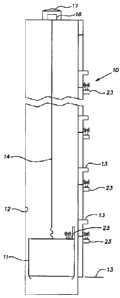
[0007] FIG. 1 is a schematic elevational view of a
hoistway in which the invention is used;
[0008] FIG. 2 is a schematic elevational view, from
the car side, of a typical landing door control system;
[0009] FIG. 3 is a schematic elevational view of a
car door control system;
[0010] FIG. 4 is a schematic view of a door
controller;
[0011] FIG. 4A is a fragmentary enlarged view of
the output relays of the controller;
[0012] FIG. 5 is a fragmentary enlarged view of
input connections of the controller for landing door
service;
CA 02715361 2010-09-21
4
[0013] FIG. 6 is a fragmentary enlarged view of the
input connections of the controller for car door service;
[0014] FIG. 7 is a fragmentary enlarged view of the
controller showing connections to door motors at a landing;
and
[0015] FIG. 8 is a fragmentary enlarged view of the
controller showing connections to a car door motor and a
retiring cam motor.
DESCRIPTION OF THE PREFERRED EMBODIMENT
[0016] Referring to the drawings and, in particular,
FIG. 1, the invention is applied to a freight elevator
installation 10 having an elevator car 11 operating in a
hoistway 12 serving a plurality of landings 13 sometimes
referred to as floors or halls. A travel cable 14, as is
customary, connects electrical devices on the car to an
elevator controller 16 in a machine room 17.
[0017] At each landing 13, as depicted in FIG. 2, a
vertical bi-parting door 21 is power operated by a pair of
motors 22, preferably of conventional three phase design.
A single motor can be used to operate a landing door where
desired but may require a more complex door suspension.
The motors 22 are powered through a door controller 23 and
operate vertical bi-parting panels 24 of the door 21
through chains 26 in a known manner. A rotary encoder 27
monitors displacement of a chain 26 and therefore
corresponding movement of the door panels 24 producing
electrical pulses corresponding to increments of door
movement. The encoder 27 is electrically connected to the
controller 23 through wiring 28. An emergency unlocking
device (EUD) 29, known in the art, for manually releasing a
door lock 31 communicates a signal to the controller 23
CA 02715361 2010-09-21
through wiring 32. A zone switch or sensor 33, also known
in the art, indicates through wiring 34 to the controller
23 the presence or absence of the car 11 stopped at the
respective landing 13. As known in the art, the zone
switch 33 located at a landing 13 is operated by a retiring
cam, disclosed below, carried on the car 11. The zone
switch 33 is operated when the door lock 31 is unlocked.
The landing door system shown in FIG. 2 is duplicated at
each landing 13 served by the elevator car 11, although the
size (height) of the doors as well as their mass, can vary
at a given installation from landing to landing.
[0018] Referring to FIG. 3, a car door 40, often
referred to as a gate, opens and closes vertically on rails
41 that are part of the car 11. opening and closing
movement of the car door 40 is produced by a car door motor
42, preferably a conventional three phase electrical unit.
The motor 42, receiving electrical power from a door
controller 23, lifts and lowers the car door 40 with a
chain 43 as is customary. A rotary encoder 44 connected to
the controller 23 through wiring 46 signals the movement of
the car door 40 by sensing movement of the chain 43. Like
the landing door encoder 27, for a known increment of
motion of the door 40, the encoder 44 produces an
electrical pulse thereby enabling the controller 23 to
count pulses and know the speed and position of the door 40.
A retiring cam 51 known in the art pivots into or out of a
position where it unlocks a landing door lock 31. The
retiring cam 51 is retracted or "retired" upon energization
of an electric motor 52 preferably a three phase unit
operated by the car controller 23 through wiring 53; in a
customary manner, when the motor 52 is not electrically
powered, the retiring cam 51 swings to an extended position
CA 02715361 2010-09-21
6
where it unlocks the door lock 31 at the landing 13 hosting
the car 11.
[0019] A reversing edge 56 of known construction
operates as an electrical switch when it contacts an object
in its path and electrically signals the car door
controller 23 through wiring 57. As will be described
below, the car door controller 23 communicates with the
elevator controller 16 through wiring in the travel cable
14.
[0020] The landing door and car door controllers 23
can be the same or substantially the same in construction
and operation so that one can be substituted for the other
with little or no modification to obtain the desired door
operation. FIG. 4 is a diagrammatic representation of the
controller 23. The controller 23 includes a motor power
inverter circuit and a three phase drive circuit 61 that
convert regular utility power, for example 60 Hz single
phase 208-240 VAC to three phase variable voltage variable
frequency (VVVF) power in a known manner. The controller
23 also includes a power supply 62 for the electronics and
other components within the controller. Still further, the
controller 23 includes a main microprocessor 63 that
performs door control logic, directs radio communication to
the other controllers, responds to signal inputs, produces
signal outputs and drives an interactive LCD screen display,
discussed below. The controller 23, further, includes a
motor drive microprocessor 64 that operates the car or
landing doors, reads by counting the encoder signals to
learn and register the size of a door opening, and
establish the door opening movement profile. Still further,
the controller 23 includes an LCD display and user keyboard
section 65 used for set-up and adjustment of its respective
CA 02715361 2010-09-21
7
door(s) by the mechanic and for trouble shooting and
display of parameter settings for operating the door
motor(s). Typical parameters for a particular door
controller include:
[0021] door type - either car door or landing door;
[0022] channel - a unique number for the line of
doors, i.e. front or rear and/or the particular hoistway in
which the controller is used;
[0023] floor address - a unique address number for
the landing opening to which the controller is assigned;
[0024] various other parameters involving, for
example, speed, acceleration, deceleration of the door(s)
which the controller operates.
[0025] It is expected that the controller 23 can be
modified or simplified where desired such as by eliminating
one or more features or by combining features such as using
one microprocessor to serve the function of the main and
motor drive microprocessors 63, 64. For purposes herein
the term controller circuitry means one or both of the
microprocessors 63, 64 or their electronic equivalent or
equivalents.
[0026] The illustrated controller 23 has a bank of
five signal input terminals. When the controller 23 is
used to operate a landing door, the inputs are assigned to
the following door condition signals with the hall
(landing) buttons, EUDs and zone switches working as
sensors for the controller (see FIG. 5):
[0027] HOB, a hall open button input driven by a
push button switch located at the controller's landing used
to indicate that a user desires to open the door;
CA 02715361 2010-09-21
8
[0028] HCB, a hall closed button input driven by a
push button switch located at the controller's landing used
to indicate that a user desires to close the door;
[0029] STOP, a door stop button input driven by a
push button switch located at the controller's landing used
to indicate that a user desires to stop the door;
[0030] ZONE input for door zone, an input driven by
the switch 33 located within the lock 31 of each landing
door that makes up and tells the door controller that the
elevator car is stopped at its assigned landing;
[0031] EUD input (emergency unlocking device), an
input driven by a switch located in an emergency access box
or EUD 29 actuated by the elevator personnel or firefighter
used to indicate to the controller that the controller's
landing door has been accessed.
[0032] When the controller 23 is used on the car 11
to operate the car door 40, the inputs are assigned to the
following signals from the elevator controller 16 (see FIG.
6):
[0033] OPEN input - a signal command from the
elevator controller to open the doors;
[0034] CLOSE input - a signal command from the
elevator controller to close the doors;
[0035] NUDGE input - a signal command from the
elevator controller to close the car door slowly (nudging);
[0036] FAST input - a command from the elevator
controller (used for firemen) to close the doors fast;
[0037] RETCAM - an input signal command from the
elevator controller to lift the retiring cam 51 to lock the
landing door which eventually allows the car to move.
CA 02715361 2010-09-21
9
[0038] From the foregoing, it will be seen that the
controller 23 when it is assigned to the car 11 receives
commands only from the elevator controller 16.
[0039] In both landing door and car door control
service, the door controller 23 receives signals from
respective encoders 27, 44 at a group of input terminals 67.
In both service for the car or landing, the controller 23
determines the instantaneous and rest positions of its
assigned door by the number of pulses transmitted from the
associated encoder 44 or 27, e.g. starting at zero when
closed and counting backward when closing. In either
landing door control or car door control, as shown in FIGS.
7 and 8, the same set of connections 68 are used to power
the respective door motors 22, 42 and retiring cam motor 52.
[0040] The door controller 23, referencing FIG. 4,
has a bank of eight separate relay contact sets. When the
controller 23 is serving as a car door controller, these
relay outputs are available for communicating with the
elevator controller 16 through wires in the travel cable 14.
Alternatively, the door conditions which term includes hall
button conditions reflected in these several relay contacts
can be communicated through a set of output terminals 71 by,
for example, serial communication using the CAN Open Lift
profile. As shown in FIG. 4, the following relay outputs
are provided:
[0041] DOOR CLOSED;
[0042] DOOR OPEN;
[0043] USER 1 - a selectable relay output defaulted
to indicate that the door is % open;
[0044] USER 2 - a selectable relay output defaulted
to indicate that the door is % closed;
CA 02715361 2010-09-21
[0045] HALL OPEN - relays a signal that the Hall
Open Button (HOB) of the hall door is pressed;
[0046] HALL CLOSE - relays a signal that the Hall
Close Button (HCB) of the landing is pressed;
[0047] DOOR STOP - relay output indicates that the
doors have stopped unexpectedly or that the STOP button of
the hall door is pressed;
[0048] REVERSING EDGE - relay output notifies the
elevator controller that the contact type safety edge
(shown in FIG 3 at 56) on the car door 40 is activated by
contacting an object in its path.
[0049] The door controller 23, additionally,
includes a radio card 66 with RF transceiver circuitry and
antenna enabling it to communicate by two-way radio signals,
i.e. in a wireless manner, to the other nearby controllers.
The main microprocessor of the door controller 23 directs
the radio card to transmit the "token" data, by a suitable
protocol using the IEEE 802.15.4 standard, to the next
controller.
[0050] The door controller main microprocessor is
programmed to suspend operation of the doors when a safety
issue arises such as a multi-zone condition where two door
zone switches 33 are activated at one time (since the
elevator car can only be located at one floor) or when the
emergency unlocking device EUD at any floor is activated.
A multi-zone condition will be detected when the token
passing technique of the controllers reveals that two zone
switches are activated. This is accomplished by the token
identifying the landing at which a zone switch is activated
and maintaining this information as it sweeps up and down
through the controllers of the hoistway. Whenever two
landing addresses are associated with a zone switch
CA 02715361 2010-09-21
11
activation, the door controller circuitry is programmed to
discontinue door operation until the source of the error is
cured. Similarly, the controller circuitry is programmed
to discontinue door operation when ever a EUD signal is
received at any of the landings. Still further, the
controller circuitry is programmed to limit token passing
to only between the landing door controller with the
activated zone switch 33 and the car door controller for
the brief period the car door and/or a landing door are in
motion so that a delay however small, that might be
involved with the time for the token to circulate through
the landing controllers is avoided. This will avoid
delaying a signal such as when the reversing edge signal
arises.
[0051] In automatic freight elevator systems, the
position and movement of the elevator car is determined by
the elevator controller 16. Assuming the car 11 has just
arrived at a landing 13, the elevator controller 16 tells
the car controller 23 via a wire in the travel cable 14 to
the RETCAM input to extend the retiring cam, which is done
by removing power to the retiring cam motor 52 in the
illustrated embodiment. The extended retiring cam 51
unlocks the landing door lock 31 at the host landing 13 and
the zone switch 33, operated with the lock, signals the
landing door controller 23 via a wire to the ZONE input
that the car has arrived and the door has been unlocked.
The landing door controller circuitry enabled by the ZONE
input signal permits two way communication with the car
door controller and causes a wireless signal transmission
to the car door controller by way of passing the token to
the car door controller. Controller circuitry is
programmed so that landing door controllers not enabled by
CA 02715361 2010-09-21
12
the presence of a ZONE signal cannot communicate directly
by wireless transmission to the car door controller or
receive wireless signals from the car door controller.
[0052] When a landing door controller has a ZONE
input signal, its controller circuitry is programmed to add
its landing door conditions to the token and to divert the
supplemented token to the car door controller. The car
door controller, under normal circumstances, has its
controller circuitry programmed to return the token to the
landing door controller for circulation up and down the
hoistway. The supplemented token, in addition to the
external signals existing at its inputs discussed above,
signals the following landing door conditions:
[0053] Door Open Position, driven by the encoder
positioning system after the opening has been learned;
[0054] Door Closed Position, driven by the encoder
positioning system after the opening has been learned;
[0055] Other Door Positions, also driven by the
encoder used for sequencing of the hall door and car door
in the open and close cycle;
[0056] Door Stop, used to indicate that the door is
jammed or otherwise unexpectedly stopped or blocked;
[0057] Various other program related functions
including:
[0058] door ready indication, door active
indication, address number, acknowledgements.
[0059] The door controller controller circuitry is
programmed to "learn" its respective opening by initially
counting the pulses from its encoder 27 or 44 during
initial opening movement until the door stops against
travel limits on its rails. The pulse count is stored in
the memory of the controller circuitry for use in
CA 02715361 2010-09-21
13
subsequent regular opening and closing cycles.
Acceleration and deceleration profiles, during selective
portions of total door movement can be programmed in the
controller to take full advantage of the door travel length
for both opening and closing.
[0060] The car door controller circuitry is
programmed to initiate door opening when it receives a
token from the landing door controller that the zone switch
has been made and it has a door open command at the OPEN
input from the elevator controller. The car door
controller wirelessly signals the landing door controller
to open its door 21. In response to this signal, the
landing door controller supplies three phase (variable
voltage variable frequency VVVF) power to its associated
door motors 22. When the landing door controller
determines that its door 21 is 2/3 open, by encoder pulse
count, it wirelessly signals the car door controller; at
this time the car door controller initiates opening of the
car door by applying three phase (variable voltage variable
frequency VVVF) power to its motor 42. Note that at this
time, a retiring cam relay 72 (FIG. 8) has de-energized the
retiring cam motor 52 and has connected the car door
controller to the car door motor 42. The landing door
controller wirelessly signals the car door controller that
the landing door is fully open, as determined by encoder
pulse count. Thereafter, when the car door is fully open,
the car door controller signals the same to the elevator
controller 16 via the DOOR OPEN relay output.
[0061] The elevator controller 16 initiates door
closing movement with a travel cable wire signal to the car
door controller CLOSE input. The car door controller
begins door closing by powering the car door motor 42 in
CA 02715361 2010-09-21
14
reverse; when the car door is 2/3 closed, the car door
controller wirelessly signals the landing door controller
to initiate landing door closing. When the landing door is
fully closed, the landing door controller wirelessly
signals the same to the car door controller. When both the
car and landing doors have closed, the car door controller
signals the elevator controller 16 via a travel cable line
connected to the DOOR CLOSE relay output.
[0062] A travel cable wire signal to the car door
controller RETCAM input from the elevator controller 16
through operation of the relay 72 and through the motor
drive power causes the retiring cam to retire or retract
resulting in the landing door at the host landing being
locked in preparation for departure of the car.
[0063] The elevator system can continue operation
under control of the elevator controller. If an unusual
condition such as the presence of a multi-zone signal, an
EUD signal or a DOOR STOP signal produced at the landing
hosting the car occurs in the token, the car door
controllers will suspend operation of the doors.
[0064] While the foregoing disclosure describes a
freight elevator installation, the invention is applicable
to passenger elevator installations, particularly where it
is difficult to mechanically couple the car door(s) with
the landing door(s) such as in high speed systems where
close tolerances are problematic.
[0065] It should be evident that this disclosure is
by way of example and that various changes may be made by
adding, modifying or eliminating details without departing
from the fair scope of the teaching contained in this
disclosure. The invention is therefore not limited to
CA 02715361 2010-09-21
particular details of this disclosure except to the extent
that the following claims are necessarily so limited.