Note: Descriptions are shown in the official language in which they were submitted.
CA 02715620 2010-09-24
09RG 236055
BROILER FOR COOKING APPLIANCES
BACKGROUND OF THE INVENTION
The present disclosure relates generally to cooking appliances and more
particularly to
broilers for cooking appliances.
Generally, heating elements in, for example, an oven cavity of a cooking
appliance
should efficiently and evenly direct heat towards food items being cooked.
However,
conventional heating elements such as, for example, sheath heaters, halogen
lamps,
and quartz lamps, transmit heat in all directions with much of the heat being
absorbed
by the oven cavity walls. This generally results in heat not being delivered
efficiently
and directly to the food, as well as extreme heat gradients where food is
unevenly
cooked across its exposed surface. Radiant ribbon heaters transmit heat more
directional and can be more efficient in delivering heat directly to food, but
they are
generally sluggish since they require a backside insulative mat to support and
position
the ribbons and have a fair amount of heater mass to overcome. It is also the
nature of
the ribbons to be aligned width-wise in parallel with intended radiation path
to the
food rather than the more efficient perpendicular orientation.
Recently, there have been several advances in a variety of infrared quartz
tubular
heaters called carbon emitters that are produced by companies such as
Panasonic and
Heraeus Noblelight. These heaters, while encased and sealed in an inert
gaseous
environment, use a wide, yet flat carbon filament that heats up quickly and
intensely
when current is applied. The carbon filaments, which are generally made of
carbon
fibers and carbon dominated matrices, are very low in mass, and can heat up in
less
than 3 seconds and exhibit no adverse in-rush characteristics that tend to
plague some
of the more traditional heaters that principally use metallic filaments such
as tungsten.
For example, a standard quartz heater that uses a tungsten filament may have
an in-
rush current spike of 10 A compared to its eventually steady state current of
IA.
-1-
CA 02715620 2010-09-24
09RG 236055
Carbon emitters, while having no substantial in-rush surges, are also very
directional
in their ability to apply heat since the filaments are very thin and very
wide. They are
extremely efficient when the filaments within the tubes are placed in a
perpendicular
direction relative to the radiation path to the object being heated. There are
industrial
applications of carbon emitters. For example, carbon emitters have been used
to dry
coatings. However, they have not been used in either the commercial or
residential
appliance industry. With the need to limit demand peaks at the utilities and
the
difficulties to build new power plants in the US, the carbon emitter
technology
provides an opportunity to reduce the wattage required to adequate cook or
broil food
by more efficiently directing heat from the broiler above the food down onto
the food.
It would be advantageous to be able direct heat efficiently and more evenly to
the food
being cooked within an oven cavity.
BRIEF DESCRIPTION OF THE INVENTION
As described herein, the exemplary embodiments overcome one or more of the
above
or other disadvantages known in the art.
One aspect of the exemplary embodiments relates to a broiler assembly for a
cooking
appliance. The cooking appliance has an oven cavity and the broiler assembly
is
disposed within the oven cavity. The broiler assembly includes a reflector
having first
and second sides, side retainers coupled to a respective one of the first and
second
sides, and at least one carbon emitter heating element mounted to the side
retainers.
Another aspect of the exemplary embodiments relates to a cooking appliance.
The
cooking appliance includes a frame forming an oven cavity and a broiler
assembly.
The broiler assembly is disposed within the oven cavity. The broiler assembly
includes a reflector having first and second sides, side retainers coupled to
a respective
one of the first and second sides, and at least one carbon emitter heating
element
mounted to the side retainers.
Still another aspect of the disclosed embodiments relates to a carbon emitter
heating
element for a broiler assembly. The broiler assembly includes a reflector
having first
-2-
CA 02715620 2010-09-24
09RG 236055
and second sides, a first side retainer disposed on the first side of the
reflector and a
second side retainer disposed on the second side of the reflector. The first
and second
side retainers include apertures to allow mounting of the carbon emitter
heating
element laterally between the first and second sides. The carbon emitter
heating
element is a lamp having a first and second end, at least one carbon filament
disposed
within the lamp, a first insulator coupled to the first end of the lamp, and a
second
insulator coupled to the second end of the lamp. The first insulator is
configured to
engage an aperture of the first side retainer such that the first insulator is
substantially
laterally fixed within the aperture of the first side retainer. The second
insulator is
configured to engage an aperture of the second side retainer such that the
second
insulator is laterally movable within the aperture of the second side
retainer.
These as other aspects and advantages of the exemplary embodiments will become
more apparent from the following detailed description considered in
conjunction with
the accompanying drawings. It is to be understood, however, that the drawings
are
designed solely for the purposes of illustration and not as a definition of
the limits of
the invention, for which reference should be made to the appended claims.
Moreover,
the drawings are not necessarily to scale and, unless otherwise indicated,
they are
merely intended to conceptually illustrate the structures and procedures
described
herein. In addition, any suitable size, shape or type of elements or materials
could be
used.
BRIEF DESCRIPTION OF THE DRAWINGS
In the drawings:
Figs. IA and 113 are schematic illustrations of an exemplary appliance
incorporating
features in accordance with the disclosed embodiments;
Figs. 2A and 2B are schematic illustrations of a portion of the appliance of
Fig. 1 in
accordance with an exemplary embodiment;
Figs. 3A-3C are schematic illustrations of portions of a heating element in
accordance
with an exemplary embodiment;
-3-
CA 02715620 2010-09-24
09RG 236055
Figs. 4A and 4B are exemplary illustrations of broil patterns using an
appliance
incorporating aspects of the disclosed embodiments;
FIG. 5A is a heat flux pattern for a conventional sheath heater broiler; and
FIG. 5B is an exemplary heat flux pattern for a heating element of the
disclosed
embodiments.
DETAILED DESCRIPTION OF THE EXEMPLARY EMBODIMENTS OF THE
INVENTION
In one exemplary embodiment, referring to Fig. 1 A, a cooking appliance 100 is
provided. Although the embodiments disclosed will be described with reference
to
the drawings, it should be understood that the embodiments disclosed can be
embodied in many alternate forms. In addition, any suitable size, shape or
type of
elements or materials could be used. In the examples described herein, the
cooking
appliance 100 is configured as a free-standing range. However, it should be
understood that the aspects of the exemplary embodiments may be applied to any
suitable cooking appliance having any suitable oven cavity in a manner
substantially
similar to that described herein.
In one aspect, the disclosed embodiments are directed to a cooking appliance
100
having a cooktop 110, an oven 120 and a warming drawer/mini-oven 140. In this
example, the cooking appliance 100 is in the form of an electric operated free
standing
range. In alternate embodiments, the cooking appliance 100 may be any suitable
cooking appliance, including but not limited to combination induction/electric
and
gas/electric cooking appliances having, for example, the electric heating
elements
described herein. The cooking appliance also includes any suitable controller
199
configured to control the appliance 100 as described herein.
The cooking appliance 100 includes a frame or housing 130. The frame 130 forms
a
support for the cooktop 110 as well as internal cavities such as the oven
cavity 125 of
the oven 120 and/or the cavity for the warming drawer/mini-oven 140. The
cooktop
110 includes one or more cooking grates 105 for supporting cooking utensils on
the
-4-
CA 02715620 2010-09-24
09RG 236055
cooktop 110. Referring also to Fig. 1B, the oven cavity 125 is defined by a
top side
125T, a bottom side 125B, a front side 125F, a rear side 125R, and lateral
sides
12551, 125S2. The oven cavity 125 may have any suitable dimensions and
includes
one or more rack supports 190 and a broiler assembly 160. The rack supports
190
may be located at spaced apart positions A-F of the oven cavity 125. In this
example,
position A is closest to the broiler assembly 160 (e.g. the top side 125T of
the oven
cavity 125) and position F is the closest to the bottom side 125B of the oven
cavity
125. One or more oven racks 170 may be placed in a respective one of the
positions
A-F on the rack supports 190 so that food items may be placed on the oven
rack(s)
170 for cooking.
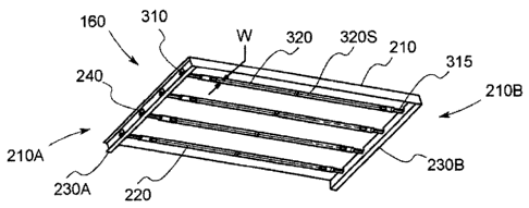
Referring to Figs. 2A and 2B, a broiler assembly 160 is shown in accordance
with an
exemplary embodiment. It should be understood that while the broiler assembly
160
is shown located at the top side 125T (Fig. 1B) of the oven cavity 125 (Fig.
1B), the
aspects of the exemplary embodiments can be equally applied to heating
elements
located at, for example, the bottom or sides of the oven cavity. In this
example, the
broiler assembly 160 includes a reflector 210, one or more heating elements
220A-
220D and side retainers 230A, 230B. The heating elements 220A-220D are
arranged
so that the heating elements 220A-220D extend laterally (e.g. between lateral
sides
12551, 125S2) within the oven cavity 125 (Fig. 1B). While the heating elements
220A-220D are arranged substantially parallel with each other, in other
examples, the
heating elements 220A-220D may be configured in any suitable arrangement for
providing a substantially uniform or even heat distribution within the oven
cavity 125
(Fig. 1 B), such as for example, with respect to a plane defined by an oven
rack 170
located at one of oven cavity cooking positions A-F.
The reflector 210 may be constructed of any suitable heat reflective material
including, but not limited to, aluminized steel. The reflector 210 may be
configured to
allow attachment of the broiler assembly 160 to, for example, the top 125T of
the
oven cavity 125 (Fig. 1 B). In alternate embodiments the reflector may be
configured
for attachment to one or more of the lateral sides 12551, 125S2 and the rear
side 125R
-5-
CA 02715620 2010-09-24
09RG 236055
of the oven cavity 125 (Fig. 113). The reflector 210 includes first and second
ends
210A, 210B.
The side retainers 230A, 230B are coupled to a respective one of the first and
second
ends 210A, 210B in any suitable manner. For example, the side retainers may be
coupled to the respective first and second ends 210A, 210B of the reflector
210 with
mechanical fasteners, chemical fasteners, welds, etc. In other examples the
side
retainers may be integrally formed (e.g. unitary one-piece construction) with
the
reflector 210. The side retainers 230A, 230B may be constructed of any
suitable
material including but not limited to aluminized steel (or any other heat
reflective
material). Each of the side retainers 230A, 230B include one or more apertures
240
configured to interface with the one or more heating elements 220A-220D.
Referring also to Figs. 3A and 3B, the one or more heating elements 220A-220D
are
carbon emitter infrared heaters or heating elements. The carbon emitter
heating
elements 220A-220D of the disclosed embodiments have a carbon filament design
that combines the versatile medium-wave spectral emission with very short
reaction
times of just seconds. In one embodiment, the carbon emitter heating elements
220A-
220D are made with fused silica or quartz tubes 325. The tubes 325 are filled
with an
inert gas, such as for example, argon. A carbon filament 320, generally in the
form of
substantially flat or thin carbon sheets, is disposed within the tube 325. In
one
embodiment, a substantially flat, wide carbon filament 320 is disposed within
a quartz
or fused silica transparent lamp 325 (e.g. a carbon emitter lamp).
The carbon filament 320 includes an insulator 310, 315 on each end that allows
the
heating element 220A to be easily placed in the oven in the proper
orientation. In the
embodiments, described herein, the proper orientation is generally with the
flat carbon
filament 320 facing the bottom of the oven. In alternate embodiment, the
orientation
of the heating elements 220A-220D is any suitable orientation that directs the
heat
evenly and efficiently to the food being cooked. The carbon filament 320 of
the
disclosed embodiments provides the highly directional characteristic to the
way the
heating element 220A delivers heat flux.
-6-
CA 02715620 2010-09-24
09RG 236055
It should be understood that while multiple individual heating elements 220A-
220D
are shown and described herein, in other examples the one or more heating
elements
220A-220D may include a substantially flat lamp assembly configured to house
multiple carbon filaments 320 to form a multi-filament lamp. Each of the
multiple
carbon filaments 320 in the multi-filament lamp may be operable in
substantially the
same manner as the individual heating elements 220A-220D as described herein.
The carbon filament 320 may have a surface 320S that is substantially flat and
has a
suitable width W. The carbon filament 320 is configured to radiate
substantially all of
its energy in a direction X (see also Fig. 1B). The direction X is
substantially
perpendicular to the surface 320S. In this fashion, substantially all of the
energy from
the carbon filament 320 is transmitted directly to food items placed beneath
the broiler
assembly 160 on the oven racks 170. In one example, the width W of the of the
carbon filament may be up to approximately 0.5 inches and the surface 320S may
be
configured to achieve an operating temperature of about 2,800 C. In other
examples,
the width W may be more or less than about 0.5 inches and the surface 320S may
be
configured to achieve an operating temperature of more or less than about
2,800 C. In
one embodiment, the length of the tubes 325 is approximately 19" with a
diameter of
approximately 0.5". Each of the heating elements 220A-220D has a heating
output of
approximately 700W. In one example, the heating elements 220A-220D are
products
of Panasonic Corp. The carbon filaments, which are approximately 16-inches in
length, can be made various ways. They are generally carbon fibers with an
inorganic
binder used to give them some structural capabilities. A metallic conductive
spring
clip (not shown) is used to electrically and structurally connect each end of
the carbon
filament to current going in and out of each heating element. This clip acts
not only as
a conductive path, but also isolates substantially from thermal expansion
during
heating and large structural loads during shipping and handling. In one
embodiment,
the one or more heating elements 220A-220D of the broiler assembly 160 are
generally configured to achieve the operating temperature within about 3
seconds of
activating the broiling elements. In alternate embodiments the operating
temperature
may be reached in a time period faster or slower than about 3 seconds.
-7-
CA 02715620 2010-09-24
09RG 236055
Each of the one or more heating elements 220A-220D includes thermal insulators
310,
315 disposed on respective ends 225, 226 of the one or more heating elements
220. In
one example, the insulators 310, 315 may be constructed of any suitable
insulating
material such as ceramic. A first insulator 310 may be disposed on end 225 of
a
respective heating element, such as heating element 220A. It should be
understood
that the other heating elements 220B-D are configured similarly to heating
element
220A. The first insulator 310 includes an insulator body 31 OB. In this
example, the
insulator body 31OB is substantially cylindrical in shape but in alternate
embodiments,
the insulator body 310B may have any suitable shape and/or cross-section. The
insulator body 310B includes an interface slot 310C configured to receive at
least a
portion of the heating element 220A for coupling the insulator 310 with the
heating
element 220A. In other examples, the insulator body 310B may have any suitable
recess or other opening for receiving at least a portion of a heating element
220A for
coupling the insulator 310 with the heating element 220A. The insulator body
31OB
also includes a retaining slot 31 OR that is configured to engage an edge of a
respective
aperture 240 in one of the side retainers 230A, 203B for stationarily locating
the
heating element 220A within the broiler assembly 160.
The second insulator 315 may be disposed at the opposite end 226 of the
heating
element 220A. The second insulator 315 includes an insulator body 315B. In
this
example, the insulator body 315B is substantially cylindrical in shape but in
other
examples the insulator body 315B may have any suitable shape and cross-
section.
The insulator body 315B includes an interface slot 315C that is substantially
similar to
the interface slot 31OC described above for coupling the insulator 315 to the
heating
element 220A. In other examples, the insulator body 315B may have any suitable
recess or other opening for receiving at least a portion of a heating element
220A for
coupling the insulator 310 with the heating element 220A. The insulator body
315B
also includes a retaining surface 3155. The retaining surface 315S is
configured to
engage an edge of a corresponding aperture 240 in another one of the side
retainers
230A, 203B for supporting the heating element 220A in the broiler assembly
160.
The retaining surface 315S is a substantially flat surface that allows the
heating
element 220A and insulator 315 to float or move around within the
corresponding
-8-
CA 02715620 2010-09-24
09RG 236055
aperture 240 of the other side retainer 230A, 230B. In other examples, the
insulators
310, 315 may have any suitable shapes and configurations for locking a
respective one
of the one or more heating elements 220A-220D to one of the side retainers
230A,
230B while allowing the one of the one or more heating elements 220A-220D to
move within another one of the side retainers 230A, 230B.
Referring again to Fig. 2A and also to Figs. 4A and 4B, compared with
conventional
heaters, the broiler assembly 160 described herein provides a relatively
uniform heat
distribution within the oven cavity 125 (Fig. 1B). As can be seen in Fig. 4A,
a toast
pattern 400 is illustrated with respect to slices of bread placed on an oven
rack 170
located at, for example, oven cavity cooking position D. As can be seen in
Fig. 4A,
the toast pattern 400 is relatively even from front 170F to back 170R as well
as side to
side 170S1, 170S2 (corresponding to the front 125F, back 125R and lateral
sides
125S1, 1252 of the oven cavity, Figs. IA and 113) along the oven rack 170.
Fig. 4B
illustrates another toast pattern 410 illustrated with respect to slices of
bread placed on
the oven rack 170 located at oven cavity cooking position C. As can be seen in
Fig.
4B, the toast pattern 410 is relatively even from front 170F to back 170R and
side to
side 170S1, 170S2 along the oven rack 170. Compared with conventional heaters
such as sheath heaters, halogen lamps, etc, the broiler assembly 160 of the
present
disclosure reduces the energy usage by about 2/3 while still being able to
provide a
comparable heating or browning performance and a relatively even heat
distribution.
Referring to FIGS. 5A and 513, examples of heat flux patterns for both a
conventional
sheath heater broil element and a carbon emitter heating element of the
disclosed
embodiments are illustrated. The plot shown in FIG. 5A illustrates how the
heat flux
emitted by a conventional sheath heater broil element varies as a function of
both
vertical spacing from the food and lateral position within the oven cavity.
Curve 502
represents a vertical distance of approximately 2 inches from the broil
element.
Curves 504, 506 and 508 represent vertical distances of approximately 4, 6 and
8
inches, respectively, from the broil element. As shown by curve 502, the
gradients,
such as points 510 and 512, become excessively large as the food is pushed
closer to
broil element, resulting in uneven browning and cooking. As the food is
lowered
-9-
CA 02715620 2010-09-24
09RG 236055
away from the broil element, the gradients become less severe, but the flux
intensity
drops off significantly, resulting in longer cooking times.
In FIG. 513, the heat flux intensity is again shown as a function of vertical
spacing
from the heating clement and lateral spacing within oven cavity, where the
heating
element is the carbon emitter heating element, such as element 220A, of the
disclosed
embodiments. Here, curve 520 represents a vertical distance of approximately 2
inches from the heating element, while curves 522, 524 and 528 represent
vertical
distances of approximately 4, 6 and 8 inches, respectively, from the heating
element
As shown in FIG. 5B, the gradients, such as gradients 528 and 530, are much
lower
for this broiler. In particular, the flux intensity stays relatively constant,
which means
food can be ensured of cooking evenly and quickly regardless of its placement
in the
oven.
In one aspect of the exemplary embodiments, the controller 199 (Fig. IA) may
be
configured to individually cycle (e.g. turn on and off) each of the one or
more heating
elements 220A-220D. Individually cycling the one or more heating elements 220A-
220D may allow for a more even heat distribution (e.g. front to back and side
to side
with respect to a plane of a given oven cavity cooking position A-F) than if
all of the
one or more heating elements are continuously active. The cycling of the
heating
elements 220A-220D may also allow for the placement of food on oven racks at
closer
distances to the one or more heating elements 220A-220D.
The exemplary embodiments described herein provide a broiler assembly 160
(Fig.
1 B) that directs substantially all of its energy towards food placed within
the oven
cavity 125 (Figs. IA and 113) adjacent the broiler assembly 160. This provides
for
increased efficiency (e.g. energy into the food versus energy supplied in the
oven
cavity) by about 25% compared to conventional broilers, as well as a more even
application of heat across the food tray and the food being cooked. The
increased
efficiency may translate into less energy needed to cook food, less preheat
needed to
reach a desired operating temperature, potentially faster cooking times and
more even
cooking.
-10-
CA 02715620 2010-09-24
09RG 236055
Thus, while there have been shown and described and pointed out fundamental
novel
features of the invention as applied to the exemplary embodiments thereof, it
will be
understood that various omission and substitutions and changes in the form and
details
of devices illustrated, and in their operation, may be made by those skilled
in the art
without departing from the spirit of the invention. For example, it is
expressly
intended that all combinations of those elements and/or method steps, which
perform
substantially the same way to achieve the same results, are with the scope of
the
invention. Moreover, it should be recognized that structures and/or elements
and/or
method steps shown and/or described in connection with any disclosed form or
embodiment of the invention may be incorporated in any other disclosed or
described
or suggested form or embodiment as a general matter of design choice. It is
the
intention, therefore, to be limited only as indicated by the scope of the
claims
appended hereto.
-11-