Note: Descriptions are shown in the official language in which they were submitted.
CA 02715642 2010-08-13
WO 2009/103012 PCT/US2009/034137
TISSUE ENGINEERING SCAFFOLDS
Field of the Invention
The present invention relates to tissue engineering scaffolds that mimic the
biomechanical
behavior of native blood vessels, and methods of making and using the same.
Background of the Invention
A major problem in blood vessel tissue engineering is the construction of
vessel grafts that
possess suitable, long-lasting biomechanical properties commensurate with
native vessels. Arterial
replacements pose special challenges due to both the cyclic loading common to
all vessels, but
additionally the higher operating pressure required of those vessels.
Researchers have approached
this problem through a variety of synthetic and organic materials, different
construction modalities
(e.g. electrospinning and casting) and numerous composite designs. For
example, attempts have been
made to create blood vessel grafts using various combinations of donor grafts,
natural components,
and synthetic components (see e.g. Zilla et al., U.S. Published Patent
Application 2005/0131520;
Flugelman, U.S. Published Patent Application 2007/0190037; Shimizu, U.S.
Patent 6,136,024;
Matsuda et al., U.S. Patent 5,718,723; and Rhee et al., U.S. Patent
5,292,802). Other scaffolds
composed of poly (ester urethane) ureas (PEUU) (Courtney et al. (2006)
Biomaterials. 27:3631-
3638), and PEUU/collagen (Guan et al. (2006) Cell Transplant. Vol. 15. Supp.
1;517-S27) have been
reported as exhibiting tissue-like functional properties. However, although
synthetic materials such
as Dacron (ethylene terephthalate) and PTFE (Teflon) have been successfully
used for large
diameter vessels, no synthetic material has been successfully utilized for
small diameter (e.g. less
than 6 mm internal diameter) vascular grafts. Vascular grafts composed of
Dacron (ethylene
terephthalate) and PTFE having an internal diameter of less than 5 mm have
been found to be
clinically unacceptable due to acute thrombus formation and chronic
anastomotic and/or intimal
hyperplasia (Walpoth et al. (2005) Expert Rev. Med. Dev. 2(6):647-51). The
elusive success of
small-diameter vascular grafts might be in part attributable to factors
including the failure to properly
match in vivo mechanical properties.
The biomechanical properties of native blood vessels have been extensively
characterized. It
has become apparent that their response to stress and strain is an important
feature (Roach et al.
(1957) Can. J. Biochem. Physiol. 35:681-690; Gosline & Shadwick (1998)
American Scientist.
86:535-541). Materials that exhibit a stress-strain curve known as a "J-
shaped" curve are candidates
that may be suitable for use in a tissue engineering scaffold, such as a blood
vessel scaffold, wherein
a mechanical response to stress and strain resembling that of a native blood
vessel is desirable. The
mechanical properties of various fabricated scaffolds made from blends of
elastin, collagen, and
CA 02715642 2010-08-13
WO 2009/103012 PCT/US2009/034137
synthetic polymers have been reported (Lee et al. (2007) J. Biomed, Mater.
Res. A., Dec
15;83(4):999-1008; Smith et al. (2008) Acta Biomater. Jan;4(1):58-66; Lelkes
et al. U.S. Published
App. No. 2006/0263417). However, there remains a need for tissue engineering
scaffolds that are
capable of recapitulating the J-shaped curve behavior, and methods for making
such scaffolds.
The present invention provides tissue engineering scaffolds that exhibit the
same type of
response to stress and strain, namely a J-shaped stress/strain curve, that is
observed in native blood
vessels, and methods of using and making the same.
Summary of the Invention
The present invention concerns tissue engineering scaffolds and methods of
making the
same.
In one aspect, the present invention provides methods of making a tissue
engineering scaffold
that includes two or more different tubular elements. In one embodiment, the
method includes the
steps of (a) providing a first tubular element having an elastomeric element,
an exterior surface, an
interior luminal surface, and a first diameter; (b) dilating the first tubular
element to a second
diameter; (c) providing a second tubular element having a tensile element, an
exterior surface and an
interior luminal surface on the exterior surface of the dilated tubular
element of step (b); (d) bonding
the exterior surface of the dilated first tubular element of step (b) with the
interior luminal surface of
the second tubular element; and (e) decreasing the second diameter of the
first tubular element to the
first diameter of step (a).
In one embodiment, the first tubular element of step (a) and/or the second
tubular element of
step (c) is formed by electrospinning. In another embodiment, the first
tubular element of step (a) is
formed by electrospinning a material on a surface. In other embodiments, the
second tubular element
of step (c) is formed by electrospinning a material on the exterior surface of
the dilated first tubular
element, or by placing a pre-formed second tubular element on the exterior
surface of the dilated first
tubular element. In yet another embodiment, the first tubular element of step
(a) is formed by
electrospinning, and the second tubular element of step (c) is provided by
placing a pre-formed
second tubular element on the exterior surface of the dilated first tubular
element.
In one other embodiment, the bonding step of (d) comprises adhering the
interior surface of
the second tubular element to the exterior surface of the dilated first
tubular element. In another
embodiment, the bonding step (d) is performed after a second tubular element
is electrospun on the
exterior surface of the dilated first tubular element, or after the placement
of a pre-formed second
tubular element on the exterior surface of the dilated first tubular element,
and includes the step of
applying an additional layer of material on the outer surface of the second
tubular element to allow
adhesion sandwiching of the second tubular element between the first tubular
element and the
2
CA 02715642 2010-08-13
WO 2009/103012 PCT/US2009/034137
additional layer of material. In another embodiment, the additional layer is
or contains the same type
of material that was used to form the first tubular layer.
In another embodiment, the outer layer or surface of the second tubular
element of step (c)
above is corrugated. In one embodiment, the corrugated second tubular element
has a fibrous
network in which the fiber direction is oriented circumferentially. In other
embodiments, the outer
layer or surface of a third, fourth, fifth, etc. tubular element is corrugated
and/or has a fibrous
network in which the fiber direction is oriented circumferentially.
In some embodiments, the providing step of (a) and/or the providing step of
(c) includes
electrospinning material on a mandrel. In another embodiment, the providing
step of (c) comprises
placing a pre-formed second tubular element over the dilated first tubular
element of step (b). In one
other embodiment, the providing step of (a) comprises electrospinning a
material on a mandrel to
form a first tubular elment, and the providing step of (c) comprises placing a
pre-formed second
tubular element over the dilated first tubular element of step (b).
In other embodiments, the formation of additional tubular elements includes
electrospinning
on a mandrel, or placement of additional pre-formed tubular elements over the
existing tubular
element layers.
In other embodiments, steps (a) and (c) include casting techniques.
In one other
embodiment, step (a) involves the use of a cast corresponding to the first
diameter and step (c)
involves the use of a cast corresponding to the second diameter. In other
embodiments, the formation
of additional tubular elements includes casting, such as through the use of a
cast corresponding to a
diameter greater than or less than the second diameter of step (c); and/or
through the use of a cast
corresponding to a greater than or less than the diameter of the first
diameter of step (a).
In all embodiments, the methods of the present invention may include the step
of providing a
continuum of tensile elements or continuum of stiffening within the second
tubular element structure.
In one embodiment, the continuum is attributable to the varying morphology of
the fibers within the
second tubular element material.
In all embodiments, the step of providing tubular elements contemplates the
use of one or
more of the following: casting, the use of pre-formed tubular elements, and
electrospinning
techniques.
In all embodiments, the methods of the present invention contemplate the
provision of
additional tubular elements over the first and second tubular elements, such
as a third tubular
element, a fourth tubular element, a fifth tubular element, etc. In all
embodiments, each additional
tubular element may include one or more elastomeric elements and/or one or
more tensile elements.
Those of skill in the art will appreciate the variety of techniques for
providing additional tubular
elements, including but not limited to those described herein.
3
CA 02715642 2010-08-13
WO 2009/103012 PCT/US2009/034137
In another embodiment of the present invention, the elastomeric element
includes an
elastomeric component having a first elastic modulus, and the tensile element
includes a tensile
component having a second elastic modulus that is greater than the first
elastic modulus. In a
preferred embodiment, the second elastic modulus is greater than the first
elastic modulus by at least
one order of magnitude.
In some embodiments, the elastomeric element includes a natural elastomeric
component, a
synthetic elastomeric component, or a natural elastomeric component and a
synthetic elastomeric
component. In one embodiment, the natural elastomeric component is
elastin. In other
embodiments, the natural elastomeric component is selected from the group
consisting of elastin,
resilin, abductin, and silk. In another embodiment, the synthetic elastomeric
component may be
selected from the group consisting of latex, a polyurethane (PU),
polycaprolactone (PCL), poly-L-
lactide acid (PLLA), polydiaxanone (PDO), poly(L-lactide-co-caprolactone)
(PLCL), and
poly(etherurethane urea) (PEUU).
In other embodiments, the tensile element includes a natural tensile
component, a synthetic
tensile component, or a natural tensile component and a synthetic tensile
component. In one
embodiment, the natural tensile component is collagen. In other embodiments,
the natural tensile
component is selected from the group consisting of collagen, cellulose, silk,
and keratin. In another
embodiment, the synthetic tensile component is selected from the group
consisting of nylon,
Dacron (polyethylene terephthalate (PET)) Goretex (polytetrafluoroethylene),
polyester,
polyglycolic acid (PGA), poly-lactic-co-glycolic acid (PLGA), and
poly(etherurethane urea) (PEUU).
In another aspect, the present invention provides tissue engineering scaffolds
made by the
methods described herein having properties that mimic or are substantially
similar to those of native
blood vessels. In one embodiment, the present invention provides a tissue
engineering scaffold
having a mechanical response to stress and strain is substantially similar to
that of a response by a
native blood vessel that has (a) a first tubular element with an elastomeric
element, an exterior
surface and an interior luminal surface; and (b) a second tubular element with
a tensile element, an
exterior surface and an interior luminal surface in contact with the exterior
surface of the first tubular
element, wherein the tissue engineering scaffold's mechanical response to
stress and strain is
characterized by a J-shaped stress/strain curve.
In all embodiments, the scaffolds of the present invention contemplate one or
more additional
tubular elements with the first and the second tubular elements. In some
embodiments, the additional
tubular element(s) are formed on the exterior surface of the second tubular
element.
In another embodiment, the tissue engineering scaffold having a mechanical
response to
stress and strain substantially similar to that of a response by a native
blood vessel has (a) a first
tubular element with an elastomeric element, an exterior surface and an
interior luminal surface; and
4
CA 02715642 2010-08-13
WO 2009/103012 PCT/US2009/034137
(b) a second tubular element with a tensile element, an exterior surface and
an interior luminal
surface in contact with the exterior surface of the first tubular element,
wherein the tissue engineering
scaffold has (i) a circumferential tube elastic modulus 1 of about 0.1 MPa to
about 0.5 MPa, (ii) a
circumferential tube elastic modulus 2 of about 3.0 MPa to about 6.0 MPa; and
(iii) a circumferential
modulus transition of about 0.57 to about 1.12.
In other embodiments, the tissue engineering scaffold's mechanical response to
stress and
strain is characterized by a J-shaped stress/strain curve.
In some embodiments, the tissue engineering scaffold's mechanical response to
stress and
strain is attributable to synergy between the elastomeric element of the first
tubular element and the
tensile element of the second tubular element. In yet another embodiment, the
elastomeric element
confers elasticity to the tissue engineering scaffold and the tensile element
confers rigidity to the
tissue engineering scaffold synergistically.
In another embodiment, the second tubular element of the tissue engineering
scaffold is
corrugated. In one embodiment, the corrugated second tubular element has a
fibrous network in
which the fiber direction is oriented circumferentially. In one other
embodiment, the axis of the
corrugations is configured parallel to the axial direction of the scaffold. In
some embodiments, the
scaffolds of the present invention contemplate one or more additional tubular
elements, such as third,
fourth, fifth, etc. tubular elements, where the outer layer or surface of a
third, fourth, fifth, etc. tubular
element is corrugated and/or has a fibrous network in which the fiber
direction is oriented
circumferentially.
Some embodiments of the present invention provide tissue engineering scaffolds
where the
elastomeric element contains an elastomeric component with a first elastic
modulus and the tensile
element contains a tensile component with a second elastic modulus that is
greater than the first
elastic modulus. In a preferred embodiment, the second elastic modulus is
greater than the first
elastic modulus by at least one order of magnitude.
In yet another embodiment, the present invention provides tissue engineering
scaffolds where
the elastomeric element has a natural elastomeric component, a synthetic
elastomeric component, or a
natural elastomeric component and a synthetic elastomeric component. In one
embodiment, the
natural elastomeric component is elastin. In other embodiments, the natural
elastomeric component
is selected from the group consisting of elastin, resilin, abductin, and silk.
In other embodiments, the
synthetic elastomeric component is selected from the group consisting of
latex, a polyurethane (PU),
polycaprolactone (PCL), poly-L-lactide acid (PLLA), polydiaxanone (PDO),
poly(L-lactide-co-
caprolactone) (PLCL), and poly(etherurethane urea) (PEUU). In some
embodiments, the scaffolds of
the present invention include (i) two or more different types of natural
elastomeric components;
and/or (ii) two or more different types of synthetic elastomeric components.
5
CA 02715642 2010-08-13
WO 2009/103012 PCT/US2009/034137
In other embodiments, the present invention provides tissue engineering
scaffolds where the
tensile element has a natural tensile component, a synthetic tensile
component, or a natural tensile
component and a synthetic tensile component. In one embodiment, the natural
tensile component is
collagen. In other embodiments, the natural tensile component is selected from
the group consisting
of collagen, cellulose, silk, and keratin. In another embodiment, the
synthetic tensile component is
selected from the group consisting of nylon, Dacron (polyethylene
terephthalate (PET)) Goretex
(polytetrafluoroethylene), polyester, polyglycolic acid (PGA), poly-lactic-co-
glycolic acid (PLGA),
and poly(etherurethane urea) (PEUU). In some embodiments, the tensile element
of a scaffold
includes (i) two or more different types of natural tensile components; and/or
(ii) two or more
different types of synthetic tensile components.
In another embodiment, a tissue engineering scaffold of the present invention
has at least one
of the following: (i) a pore gradient where the pore diameter gradually
decreases from about 100
microns at the exterior surface of the second tubular element to about 5 to
about 15 microns at the
interior surface of the first tubular element; (ii) a circumferential tube
toughness of about 0.45 MJ/m3
to about 1.0 MJ/m3; (iii) an axial tube toughness of about 0.1 MJ/m3 to about
0.5 MJ/m3; (iv) a
tangent delta of about 0.05 to about 0.3; and (v) a storage modulus of about
400 MPa to about 0.12
MPa. In one embodiment, the pore gradient contributes to the enhancement of
cell seeding capacity
for a TE scaffold. In another embodiment, the axial toughness and/or
circumferential toughness
contribute to the rendering of a scaffold resistant to fracture or tearing. In
one other embodiment, the
viscoelasticity of a TE scaffold is characterized by the tangent delta and/or
storage modulus values.
In all embodiments, the TE scaffolds of the present invention may include
tubular elements
in addition to a first and second tubular elements. Those of skill in the art
will appreciate the variety
of components that may be contained in the additional tubular elements,
including but not limited to
those described herein.
In additional embodiments, the invention provides methods of making tissue
engineered
scaffolds. In one embodiment, the method comprises the steps of (a) providing
a first tubular element
comprising an elastomeric element, an exterior surface, an interior luminal
surface, and a first
diameter; (b) dilating the first tubular element to a second diameter; (c)
providing a second tubular
element comprising a tensile element, an exterior surface and an interior
luminal surface on the
exterior surface of the first tubular element of step (b); (d) completing
providing step (a) prior to
completing providing step (c); (e) bonding the dilated tubular element of step
(b) and the second
tubular element of step (c); and (e) decreasing the second diameter of the
first tubular element to the
first diameter of step (a). In another embodiment, the tissue engineering
scaffold comprises a zonal
gradation at the interface between the first tubular element and the second
tubular element. In
another embodiment, the zonal gradation comprises a transitional zone of
heterogeneity comprising
6
CA 02715642 2010-08-13
WO 2009/103012 PCT/US2009/034137
the elastomeric element of the first tubular element and the tensile element
of the second tubular
element.
In one other embodiment, the method of making tissue engineered scaffolds
comprises the
steps of: (a) providing a first tubular element comprising an elastomeric
element, an exterior surface,
an interior luminal surface, and a first diameter; (b) dilating the first
tubular element to a second
diameter at a continuous rate; (c) providing a second tubular element
comprising a tensile element, an
exterior surface and an interior luminal surface on the exterior surface of
the first tubular element of
step (b) during dilating step (b); (e) bonding the dilated tubular element of
step (b) and the second
tubular element of step (c); and (e) decreasing the second diameter of the
first tubular element to the
first diameter of step (a). In another embodiment, the second tubular element
comprises a continuum
of tensile elements or a continuum of stiffening. In one other embodiment, the
continuum of tensile
elements engages at different strain values. In another embodiment, the
bonding step (d) comprises
binding of fibers of the second tubular element to the first tubular element,
thereby providing the
continuum. In one embodiment, the fibers of the second tubular element are
linked prior to providing
step (c). In another embodiment, the fibers engage at varying intervals upon
strain depending upon
the degree of kinking. In one embodiment, the fibers without a lesser amount
of kinking straighten
and engage before the fibers with a greater amount of kinking. In another
embodiment, the fiber
engagement leads to a gradual rounding of a stress/strain curve, thereby
providing mechanical
properties similar to a native blood vessel.
In another embodiment, the method further comprises (f) providing a third
tubular element
comprising an exterior surface and an interior luminal surface on the exterior
surface of the second
tubular element. In another embodiment, the method further comprises (g)
providing a fourth tubular
element comprising an exterior surface and an interior luminal surface on the
exterior surface of the
third tubular element. In one other embodiment, the method further comprises
(h) providing a fifth
tubular element comprising an exterior surface and an interior luminal surface
on the exterior surface
of the fourth tubular element. In one embodiment, the method further comprises
providing one or
more additional tubular elements comprising an exterior surface and an
interior luminal surface, such
that the interior luminal surface of each additional tubular element is
contacted with the outermost
tubular element. In one embodiment, the additional tubular element(s) comprise
an elastomeric
element. In one embodiment, the additional tubular element(s) comprise a
tensile element. In
another embodiment, the bonding step (e) comprises providing an additional
tubular element
comprising an elastomeric element, an exterior surface, and an interior
luminal surface on the exterior
surface of the second tubular element. In one other embodiment, the
In other embodiments, the present invention provides tissue engineering
scaffolds. In one
embodiment, the tissue engineering scaffold has a mechanical response to
stress and strain is
7
CA 02715642 2010-08-13
WO 2009/103012 PCT/US2009/034137
substantially similar to that of a response by a native blood vessel, the
scaffold comprising (a) a first
tubular element comprising an elastomeric element, an exterior surface and an
interior luminal
surface; and (b) a second tubular element comprising a tensile element, an
exterior surface and an
interior luminal surface in contact with the exterior surface of the first
tubular element, wherein the
tissue engineering scaffold comprises at least one of (i) a circumferential
tube elastic modulus I of
about 0.1 MPa to about 0.5 MPa, (ii) a circumferential tube elastic modulus 2
of about 3.0 MPa to
about 6.0 MPa; and (iii) a circumferential modulus transition of about 0.57
MPa to about 1.12 MPa;
(iv) a pore gradient where the pore diameter gradually decreases from about
100 microns at the
exterior surface of the second tubular element to about 5 to about 15 microns
at the interior surface of
the first tubular element; (v) a circumferential tube toughness of about 0.45
MJ/m3 to about 1.0
MJ/m3; (vi) an axial tube toughness of about 0.1 MJ/m3 to about 0.5 MJ/m3;
(vii) a tangent delta of
about 0.05 to about 0.3; and (viii) a storage modulus of about 400 MPa to
about 0.12 MPa, or any
combination thereof. In another embodiment, the the tissue engineering
scaffold's mechanical
response to stress and strain is characterized by a J-shaped stress/strain
curve. In one embodiment,
the tissue engineering scaffold is accessible to cells. In another embodiment,
the tissue engineering
scaffold is fracture-resistant. In yet another embodiment, the tissue
engineering scaffold is
viscoelastic.
In one other embodiment, the present invention provides a tissue engineering
scaffold
comprising (a) a first tubular element comprising an elastomeric element, an
exterior surface and an
interior luminal surface; and (b) a corrugated second tubular element
comprising a tensile element, an
exterior surface and an interior luminal surface in contact with the exterior
surface of the first tubular
element.
In yet further embodiments, the present invention provides tissue engineered
blood vessels
(TEBVs). In one embodiment, the TEBV comprises (a) a first tubular element
comprising (i) an
elastomeric element, (ii) an exterior surface, (iii) an interior luminal
surface; (b) a second tubular
element comprising (i) a tensile element, (ii) an exterior surface, (iii) an
interior luminal surface in
contact with the exterior surface of the first tubular element, and (c) a
first cell population, wherein
the TEBV's mechanical response to stress and strain is characterized by a J-
shaped stress/strain
curve. In another embodiment, the TEBV comprises (a) a first tubular element
comprising (i) an
elastomeric element, (ii) an exterior surface, (iii) an interior luminal
surface; (b) a second tubular
element comprising (i) a tensile element, (ii) an exterior surface, (iii) an
interior luminal surface in
contact with the exterior surface of the first tubular element, and (c) a
first cell population, wherein
the TEBV comprises at least one of (i) a circumferential tube elastic modulus
1 of about 0.1 MPa to
about 0.5 MPa, (ii) a circumferential tube elastic modulus 2 of about 3.0 MPa
to about 6.0 MPa; and
(iii) a circumferential modulus transition of about 0.57 MPa to about 1.12
MPa; (iv) a pore gradient
8
CA 02715642 2010-08-13
WO 2009/103012 PCT/US2009/034137
where the pore diameter gradually decreases from about 100 microns at the
exterior surface of the
second tubular element to about 5 to about 15 microns at the interior surface
of the first tubular
element; (v) a circumferential tube toughness of about 0.45 MJ/m3 to about 1.0
MJ/m3; (vi) an axial
tube toughness of about 0.1 MJ/m3 to about 0.5 MJ/m3; (vii) a tangent delta of
about 0.05 to about
0.3; and (viii) a storage modulus of about 400 MPa to about 0.12 MPa. In
another embodiment, the
TEBV is characterized by a J-shaped stress/strain curve. In one embodiment,
the TEBV's
mechanical response to stress and strain is attributable to synergy between
the elastomeric element of
the first tubular element and the tensile element of the second tubular
element. In another
embodiment, the elastomeric element confers elasticity to the TEBV and the
tensile element confers
rigidity to the TEBV synergistically. In other embodiments, the second tubular
element is
corrugated. In another embodiment, the corrugated second tubular layer
comprises a fibrous network
in which the fiber direction is oriented circumferentially. In another
embodiment, the elastomeric
element comprises an elastomeric component with a first elastic modulus and
the tensile element
comprises a tensile component with a second elastic modulus that is greater
than the first elastic
modulus. In other embodiments, the second elastic modulus is greater than the
first elastic modulus
by at least one order of magnitude. In another embodiment, the elastomeric
element comprises a
natural elastomeric component. In other embodiments, the elastomeric element
comprises a synthetic
elastomeric component. In another embodiment, the elastomeric element
comprises a natural
elastomeric component and a synthetic elastomeric component. In one
embodiment, the natural
elastomeric component is selected from the group consisting of elastin,
resilin, abductin, and silk. In
another embodiment, the synthetic elastomeric component is selected from the
group consisting of
latex, a polyurethane (PU), polycaprolactone (PCL), poly-L-lactide acid
(PLLA), polydiaxanone
(PDO), poly(L-lactide-co-caprolactone) (PLCL), and poly(etherurethane urea)
(PEUU). In one
embodiment, the tensile element comprises a natural tensile component. In one
embodiment, the
tensile element comprises a synthetic tensile component. In one embodiment,
the tensile element
comprises a natural tensile component and a synthetic tensile component. In
one embodiment, the
natural tensile component is selected from the group consisting of collagen,
cellulose, silk, and
keratin. In one embodiment, the synthetic tensile component is selected from
the group consisting of
nylon, Dacron (polyethylene terephthalate (PET)) Goretex
(polytetrafluoroethylene), polyester,
polyglycolic acid (PGA), poly-lactic-co-glycolic acid (PLGA), and
poly(etherurethane urea) (PEUU).
In one embodiment, the first cell population is within the second tubular
element and/or on the
exterior surface of the second tubular element. In one embodiment, the first
cell population is a
smooth muscle population. In one embodiment, the tubular scaffold further
comprises a second cell
population. In another embodiment, the second cell population is on and/or
within the interior
9
CA 02715642 2010-08-13
WO 2009/103012 PCT/US2009/034137
luminal surface of the first tubular element. In one embodiment, the second
cell population is an
endothelial cell population.
In another embodiment, the present invention provides a TEBV comprising (a) a
first tubular
element comprising (i) an elastomeric element, (ii) an exterior surface, (iii)
an interior luminal
surface; (b) a corrugated second tubular element comprising (i) a tensile
element, (ii) an exterior
surface, (iii) an interior luminal surface in contact with the exterior
surface of the first tubular
element, and (c) a first cell population.
In yet further embodiments, the present invention provides a method of making
tissue
engineered blood vessels (TEBVs) comprising the steps of: (a) providing a
first tubular element
comprising an elastomeric element, an exterior surface, an interior luminal
surface, and a first
diameter; (b) dilating the first tubular element to a second diameter;(c)
providing a second tubular
element comprising a tensile element, an exterior surface, a first cell
population on the exterior
surface of and/or within the second tubular element and an interior luminal
surface on the exterior
surface of the first tubular element of step (b); (d) bonding the dilated
tubular element of step (b) and
the second tubular element of step (c); (e) decreasing the second diameter of
the first tubular element
to the first diameter of step (a) to provide the TEBV; (f) culturing the TEBV.
In one embodiment,
the second tubular element of step (c) is corrugated. In one embodiment, the
corrugated second
tubular element comprises a fibrous network in which the fiber direction is
oriented
circumferentially. In one embodiment, the providing step of (a) comprises
electrospinning an
elastomeric component on a mandrel and the providing step of (c) comprises (i)
electrospinning a
tensile component on a mandrel, and (ii) electrospraying the first cell
population on a mandrel. In
one embodiment, the electrospinning step of (i) and electrospraying step of
(ii) are concurrently
performed. In one embodiment, the method further comprises step (f) seeding
the interior luminal
surface of step (a) with a second cell population. In one embodiment, the
second cell population is an
endothelial cell population. In one embodiment, the elastomeric element
comprises an elastomeric
component with a first elastic modulus and the tensile element comprises a
tensile component with a
second elastic modulus that is greater than the first elastic modulus. In one
embodiment, the second
elastic modulus is greater than the first elastic modulus by at least one
order of magnitude. In one
embodiment, the elastomeric element comprises a natural elastomeric component.
In one
embodiment, the elastomeric element comprises a synthetic elastomeric
component. In one
embodiment, the elastomeric element comprises a natural elastomeric component
and a synthetic
elastomeric component. In one embodiment, the natural elastomeric component is
elastin. In one
embodiment, the synthetic elastomeric component is selected from the group
consisting of
polycaprolactone (PCL), poly-L-lactide acid (PLLA), polydiaxanone (PDO),
poly(L-lactide-co-
caprolactone) (PLCL), and poly(etherurethane urea) (PEUU). In one embodiment,
the tensile
CA 02715642 2010-08-13
WO 2009/103012 PCT/US2009/034137
element comprises a natural tensile component. In one embodiment, the tensile
element comprises a
synthetic tensile component. In one embodiment, the tensile element comprises
a natural tensile
component and a synthetic tensile component. In one embodiment, the natural
tensile component is
collagen. In one embodiment, the synthetic tensile component is selected from
the group consisting
of polyglycolic acid (PGA), poly-lactic-co-glycolic acid (PLGA), and
poly(etherurethane urea)
(PEUU). In one embodiment, the method further comprises contacting the TEBV of
step (e) with at
least one additional cell population prior to step (0 or after step (f). In
one embodiment, the culturing
step (f) comprises conditioning by pulsatile and/or steady flow in a
bioreactor.
In yet further embodiments, the invention is directed to tissue engineering
scaffolds (TE
scaffolds) or tissue engineered blood vessels (TEBVs) made by the methods
disclosed herein, or any
other suitable method, where the TE scaffolds or TEBVs have a zonal gradation
at the interface
between the first tubular element and the second tubular element. In other
embodiments, the zonal
gradation comprises a transitional zone of heterogeneity that includes
material from the elastomeric
element of the first tubular element and material from the tensile element of
the second tubular
element.
In certain embodiments, the invention is directed to tissue engineering
scaffolds (TE
scaffolds) or tissue engineered blood vessels (TEBVs) made by the methods
disclosed herein, or any
other suitable method, where the second tubular element of the TE scaffolds or
TEBVs have a
continuum of tensile elements or a continuum of stiffening. In other
embodiments, the continuum of
tensile elements engages at different strain values. In one embodiment, the
continuum is attributable
to the varying morphologies of the individual fibers of the second tubular
element material.
In some embodiments, the tissue engineering scaffolds (TE scaffolds) or tissue
engineered
blood vessels (TEBVs) have a zonal gradation at the interface between the
first tubular element and
the second tubular element and the second tubular element has a continuum of
tensile elements. In
other embodiments, the zonal gradation comprises a transitional zone of
heterogeneity that includes
material from the elastomeric element of the first tubular element and
material from the tensile
element of the second tubular element and/or the continuum of tensile elements
engages at different
strain values.
Brief Description of the Drawings
Figure 1 shows the stress/strain relationship of a native blood vessel, a
native blood vessel
minus collagen (labeled "Elastin"), and a native blood vessel minus elastin
(labeled "Collagen").
Figure 2 shows the "J" shaped curve approximated by distinguishing two linear
regions
relating to two different moduli.
II
CA 02715642 2010-10-26
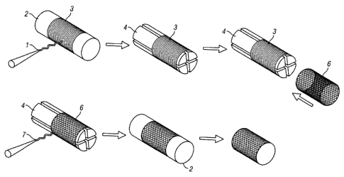
Figure 3A-B illustrates the creation of tubular structures from
electrospinning and casting.
Figure 4 illustrates the creation of tubular architectures by electrospinning.
Figures 4A-B
illustrate an electrospinning technique for providing a tissue engineered
scaffold. Figure 4C
illustrates a sudden transition between lamina (top) and a transitional mixing
of layers (bottom).
Figure 4D illustrates an electrospinning technique for achieving zonal
gradation in a tissue
engineering scaffold. Figure 4E depicts an alternative embodiment of the
expanding mandrel
process.
Figure 5A-B illustrates an expanding mandrel capable of continuous diameter
change during
rotation.
Figure 6 illustrates the application of a thin tensile mesh over an expanded
elastic lamina.
Figure 7 illustrates fiber morphologies from felt materials.
Figure 8 shows the stress/strain relationship of a latex/PDO architecture.
Figure 9 shows the stress/strain relationship of a latexNicryl architecture.
Figure 10 shows the stress/strain relationship of PDO and Vicryl.
Figure 11 shows the stress/strain relationship of latex.
Figure 12 shows the stress/strain relationship of tubes containing PGA and/or
PU.
Figure 13 shows the stress strain relationships of a tube containing PU and
PGA, and native
porcine carotid arteries.
Figure 14A-B shows a representative tubular scaffold of sutured material
around a latex tube.
Figure 15A-B shows a representative corrugated scaffold.
Figure 16A-B shows cross-sections of representative corrugated scaffolds.
Figure 17 shows the stress/strain relationship of tubes containing PLCL/PGA
and PU/PGA.
Figure 18 shows the pressure/volume relationship of tubes containing PLCL/PGA
and
PU/PGA.
Figure 19A-C depicts the concept of tunability for tubular scaffolds. A ¨
Failure of the tensile
element and failure of the elastic element coincides; B ¨ Failure of the
elastic element prior to failure
of the tensile element; C ¨ Hypothetical failure of the tensile element prior
to failure of the elastic
element.
Figure 20 shows the histochemistry of tubular scaffolds.
Figure 21A-E shows cell staining of segments of the tubular scaffolds
following cell seeding
and bioreactor conditioning.
Figure 22 shows the results of a whole blood clotting assay of the cell-
seeded, bioreactor-
conditioned tubular scaffolds.
Figure 23 shows the schematic of a bioreactor used to condition tubular
scaffolds.
12
CA 02715642 2010-08-13
WO 2009/103012 PCT/US2009/034137
DETAILED DESCRIPTION OF THE PREFERRED EMBODIMENTS
The present invention concerns tissue engineering (TE) scaffolds and methods
of making the
same. In particular, the invention provides TE scaffolds having properties
that are substantially
similar to those of native blood vessels. For example, the TE scaffolds of the
present invention
exhibit a mechanical response to stress and strain, namely a J-shaped
stress/strain curve, that is
substantially similar to that of a native blood vessel.
1. Definitions
Unless defined otherwise, technical and scientific terms used herein have the
same meaning
as commonly understood by one of ordinary skill in the art to which this
invention belongs.
One skilled in the art will recognize many methods and materials similar or
equivalent to
those described herein, which could be used in the practice of the present
invention. Indeed, the
present invention is in no way limited to the methods and materials described.
For purposes of the
present invention, the following terms are defined below.
Other relevant information is available from text books in the field of tissue
engineering,
such as, for example, Palsson, Bernhard 0., Tissue Engineering, Prentice Hall,
2004 and Principles of
Tissue Engineering, 3rd Ed. (Edited by R Lanza, R Langer, & J Vacanti), 2007.
The term "tissue engineering scaffold" or "TE scaffold" as used herein refers
to a tubular
structure that is laminated or multi-layered and characterized by an ability
to respond to stress and
strain in a manner that is substantially similar to a native blood vessel. For
example, the scaffold's
mechanical response to stress and strain is preferably characterized by a J-
shaped stress/strain curve.
The properties of the scaffolds of the present invention make them suitable
for use as a framework
for a blood vessel scaffold.
The term "tissue engineered blood vessel" or "TEBV" or "blood vessel scaffold"
as used
herein refers to a tissue engineering scaffold as defined above and described
herein that has been
further manipulated to render it suitable for transplantation into a mammalian
subject in need. For
example, the TEBV may be formed by manipulating a tissue engineering scaffold
to add one or more
cell populations by the methods described herein, or by any other suitable
method. Those of ordinary
skill in the art will appreciate that the present invention pertains to many
types of blood vessels,
including without limitation, the carotid artery, the subclavian artery, the
celiac trunk, the mesenteric
artery, the renal artery, the iliac artery, arterioles, capillaries, venules,
the subclavian vein, the jugular
vein, the renal vein, the iliac vein, the venae cavae. In addition, a TEBV of
the present invention may
also be arteriovenous shunt (AV shunt) or an inter-positional blood vessel
graft.
The term "elastomeric element" refers to a material characterized by it
ability to respond to
stress with large-scale deformations that are fully recoverable and
repeatable. The elastomeric
13
CA 02715642 2010-08-13
WO 2009/103012 PCT/US2009/034137
element may comprise a natural component, a synthetic component, or a mixture
of natural and
synthetic components.
The term "tensile element" refers to a material that is characterized by very
little ability to
elongate when stressed. The tensile element may comprise a natural component,
a synthetic
component, or a mixture of natural and synthetic components.
The term "synthetic component" as used herein refers to a component that does
not normally
exist in nature. Generally, synthetic components are not normally present in a
native blood vessel,
but nonetheless have the potential to exhibit native vessel-like properties
with respect to mechanics
and cellular behavior. A synthetic component may be part of a tissue
engineering scaffold and/or a
TEBV, as described herein, that may optionally include a natural component (as
defined below).
Synthetic components may be elastomeric or tensile in nature.
The term "natural component" as used herein refers to a substance that exists
in nature or is
derived from a substance that exists in nature, regardless of its mode of
preparation. Thus, for
example, a "natural component" may be a native polypeptide isolated and
purified from its native
source, or produced by recombinant and/or synthetic means. Natural components
may be present in a
native blood vessel and therefore have the potential to exhibit native vessel-
like properties with
respect to mechanical and cellular behavior. In certain embodiments, natural
components may be
elastomeric or tensile in nature.
The term "corrugated" as used herein, refers to a structure containing a
tensile component
characterized by corrugations, undulations, and/or kinks on one or more of its
surfaces. This
structure is generally in the form of a thin layer or lamina made up of a
fibrous network in which the
fiber direction is generally oriented circumferentially. In addition, the axis
of the corrugations is
configured to be parallel to the axial direction of the structure, e.g., a
tubular tissue engineering
scaffold.
The term "mechanical response" or "biomechanical response" as used herein
refers to the
behavior exhibited by a native blood vessel, blood vessel scaffold, or tissue
engineering scaffold
when subjected to stress and strain. The behavior upon exposure to stress and
strain is preferably
characterized by one or more of the following: (i) a J-shaped stress/strain
curve; (ii) viscoelasticity;
and (iii) resistance to tearing or fracturing.
The term "substantially similar to a native blood vessel" as used herein
refers to a scaffold
having mechanical properties that closely mimic or resemble those of a native
blood vessel. Those of
ordinary skill in the art will appreciate that several parameters can be
characterized and measured to
demonstrate this substantial similarity. Important parameters for providing
the tissue engineering
scaffolds of the present invention with mechanical behavior that is
substantially similar to a native
blood vessel, including a J-shaped stress/strain curve, are the scaffold's
circumferential tube elastic
14
CA 02715642 2010-08-13
WO 2009/103012 PCT/US2009/034137
modulus 1, circumferential tube elastic modulus 2, and the circumferential
tube's modulus transition.
In a preferred embodiment, other parameters also contribute to the desired
mechanical behavior or
response of the scaffolds to stress and strain and/or their capacity to serve
as a vascular graft,
including, without limitation, compliance, Young's or elastic modulus, burst
pressure, wall thickness,
porosity, pore diameter, pore gradient, fiber diameter, breaking strain (axial
and/or circumferential),
breaking stress (axial and/or circumferential), toughness (axial and/or
circumferential), axial tube
elastic moduli 1 and 2, the axial tube's elastic modulus transition, and
viscoelastic properties such as
those demonstrated by particular tangent delta (tan delta) and storage modulus
values.
The term "J-shaped curve" as used herein refers to the shape of the curve
where stress (force
per unit area of material or pressure) is plotted on the y-axis and strain
(change in length over the
original length or displacement) is plotted on the x-axis. The J-shaped curve
is a mechanical
response to stress and strain that is inherent to native arteries arising from
the synergistic interplay of
collagen and elastin, as depicted in Figure 1.
The term "compliance" as used herein is defined by the formula
C=A(delta)V/A(delta)P (the
slope) on a pressure (x-axis)/volume (y-axis) curve. It is the measure of
"softness" in a material and
is the inverse of "stiffness". Typically, C is mL/mm Hg where V is volume (mL)
and P is pressure
(mm Hg).
The term "Young's modulus" or "Elastic modulus" as used herein is defined as a
parameter
for stiffness. It is derived from the slope of a stress (y-axis)/strain (x-
axis) curve. In the case of a
non-linear "J" shaped curve, the elastic modulus can be modeled as two
separate intersecting slopes,
in which the first slope is derived from the initial quasi-linear segment
(elastic modulus 1) and the
second slope is derived from the later quasi-linear segment (elastic modulus
2). Figure 2 illustrates
this concept.
The term "elastic modulus 1 to elastic modulus 2 transition" or "modulus 1 to
modulus 2
transition" or "elastic modulus transition" as used herein refers to the range
over which the slope of
elastic modulus 1 transitions or changes to the slope of elastic modulus 2.
The unit of expression for
this parameter is a strain value at which the slope occurs. This is
illustrated in Fig. 2 where the
straight lines represented by Modulus (slope) 1 and Modulus (slope) 2
intersect. In the curve
showing the response in native blood vessels, the transition is illustrated by
the segment of the curve
indicating a change from the Modulus (slope) 1 to the Modulus (slope) 2.
The term "compliance mismatch" as used herein refers to the union of two
materials with
differing measures of softness/stiffness (i.e. compliance/Young's modulus or
Elastic modulus).
The term "porosity" as used herein is defined as the ratio of pore volume in a
scaffold to the
total volume of the scaffold, and may be expressed as a percentage porosity.
Alternatively, porosity
may be the percentage ratio of pore area in a scaffold to the total area of
the scaffold.
CA 02715642 2010-08-13
WO 2009/103012 PCT/US2009/034137
The term "burst pressure" as used herein is defined as the difference in
pressure between the
interior and exterior of a tubular scaffold which the scaffold can withstand
before at least a partial
disintegration of the scaffold occurs.
The term "wall thickness" as used herein is defined as the depth or extent
from the exterior
surface of a tubular scaffold to its interior luminal surface.
The term "pore diameter" as used herein is defined as the average diameter of
the pores
within a scaffold of the present invention.
The term "pore gradient" as used herein is defined as a linear change in pore
diameter size
from one surface to another. The pore diameter size will gradually decrease
within a layer of a
tubular element. For instance, the size can decrease from one surface, such as
the adventitial or
exterior surface of a tubular element, to another surface, such as a lumina'
or interior surface of the
tubular element.
The term "fiber diameter" as used herein is defined as the average diameter of
the fibers of a
scaffold of the present invention.
The term "breaking strain" as used herein is defined as strain at fracture in
a material.
The term "breaking stress" as used herein is defined as stress at failure in a
material.
The term "toughness" as used herein is defined as the energy required to
fracture a material,
the calculated area under a stress/strain curve to failure.
The term "tangent delta" as used herein is defined as an indicator of the
relative amounts of
energy stored and lost in a tubular scaffold and is typically used to
characterize molecular relaxations
and identify rheological transformations.
The term "storage modulus" as used herein is defined as the ability of a
material to store
mechanical energy, and is typically used to characterize molecular
relaxations.
The term "kink radius" as used herein is defined as the radius at which a kink
forms in a
flexed tubular structure.
The term "zonal gradation" as used herein is defined as a gradual gradient in
a laminate
structure having at least two different layers; where each layer contains a
different type of material;
and where the gradient exists between the layers and is a zone of
heterogeneity as between different
materials. For example, the zone of heterogeneity may contain material from an
elastomeric element
and material from a tensile element.
The term "smooth muscle cell" as used herein refers to a cell that makes up
non-striated
muscle that is found in the walls of hollow organs (e.g. bladder, abdominal
cavity, uterus,
gastrointestinal tract, vasculature, etc.) and is characterized by the ability
to contract and relax.
Vascular smooth muscle cells are found throughout the tunica media (thickest
layer of a blood
16
CA 02715642 2010-08-13
WO 2009/103012 PCT/US2009/034137
vessel), which contains a circularly arranged elastic fiber and connective
tissue. As described below,
smooth muscle cell populations can be isolated from a variety of sources.
The term "endothelial cell" as used herein refers to a cell that is suitable
for seeding on the a
scaffold of the present invention, either on the interior luminal surface or
within the scaffold.
Endothelial cells cover the interior or luminal surface of native blood
vessels and serve multiple
functions including, but not limited to, the prevention of thrombosis and the
prevention of tissue in-
growth and unwanted extracellular matrix production. As described below,
endothelial cell
populations for seeding onto scaffolds of the present invention can be
isolated from a variety of
sources including, without limitation, the vascular parenchyma, circulating
endothelial cells and
endothelial cell precursors such as bone marrow progenitor cells, peripheral
blood stem cells and
embryonic stem cells.
The term "cell population" as used herein refers to a number of cells obtained
by isolation
directly from a suitable tissue source, usually from a mammal, and subsequent
culturing in vitro.
Those of ordinary skill in the art will appreciate that various methods for
isolating and culturing cell
populations for use with the present invention and the various numbers of
cells in a cell population
that are suitable for use in the present invention.
The term "mammal" as used herein refers to any animal classified as a mammal,
including,
without limitation, humans, non-human primates, domestic and farm animals, and
zoo, sports or pet
animals such horses, pigs, cattle, dogs, cats and ferrets, etc. In a preferred
embodiment of the
invention, the mammal is a human.
The term "non-human animal" as used herein includes, but is not limited to,
mammals such
as, for example, non-human primates, rodents (e.g., mice and rats), and non-
rodent animals, such as,
for example, rabbits, pigs, sheep, goats, cows, pigs, horses and donkeys. It
also includes birds (e.g.,
chickens, turkeys, ducks, geese and the like). The term "non-primate animal"
as used herein refers to
mammals other than primates, including but not limited to the mammals
specifically listed above.
A "cardiovascular disease" or "cardiovascular disorder" is used herein in a
broad, general
sense to refer to disorders or conditions in mammals characterized by an
abnormality in the function
of the heart or blood vessels (arteries and veins) and affecting the
cardiovascular system, particularly
those diseases related to atherosclerosis. Such diseases or disorders are
particularly amenable to
treatment using a TEBV described herein as a bypass vascular graft. Such
grafts include, without
limitation, coronary artery bypass graft (CABGs), peripheral bypass grafts, or
arteriovenous shunts.
Examples of cardiovascular disorders include, without limitation, those
conditions caused by
myocardial ischemia, a heart attack, a stroke, a transmural or non-transmural
myocardial infarction,
an acute myocardial infarction, peripheral vascular disease, coronary artery
disease, coronary heart
disease, an arrhythmia, sudden cardiac death, a cerebrovascular accident such
as stroke, congestive
17
CA 02715642 2010-08-13
WO 2009/103012 PCT/US2009/034137
heart failure, a life-threatening dysrhythmia, cardiomyopathy, a transient
ischemic attack, an acute
ischemic syndrome, or angina pectoralis, acute coronary stent failure, or a
combination thereof.
Other examples of such disorders include,without limitation, thrombotic
conditions such as
pulmonary embolism, acute thrombosis of the coronary arteries, myocardial
infarction, acute
thrombosis of the cerebral arteries (stroke) or other organs.
2. J-shaped curve stress/strain response
Figure 1 depicts a J-shaped curve, which is a mechanical response to stress
and strain
inherent to native arteries that arises from the synergistic interplay of two
major structural proteins,
collagen and elastin (Roach et al. (1957) Can. J. Biochem. Physiol. 35:681-
690). Native vessel
mechanics are nonlinear and chacterized by a "1" shaped curve on a force
(stress)/displacement
(strain) diagram resulting from the synergistic interplay of collagen and
elastin (Figure 2). The
presence of both collagen and elastin in arteries gives them their profound
nonlinear behavior. If a
native artery has its elastin extracted leaving collagen as the remaining
primary structural protein, the
mechanical response becomes much stiffer. Conversely, if a native artery is
treated to remove
collagen, the predominant structural protein is elastin, and the mechanics
reflect a linear elastic
character. The "J" shaped curve of the native artery is non-linear behavior
resulting from the
combined effects of both collagen and elastin, the major structural proteins
present in arteries
(Gosline & Shadwick (1998) American Scientist. 86:535-541).
In this biological composite, collagen behaves as a high stiffness, low
elasticity component
while elastin behaves as the high elasticity, low stiffness element. Collagen
is a tensile element with
very little ability to elongate when stressed and thus is particularly suited
to roles in tissues such as
tendon and ligament. Elastin, however, is characterized by its ability to
respond to stress with large-
scale deformations that are fully recoverable and repeatable. These
characteristics of elastin make it
suitable for tissues that require some sort of recoil or restoring force such
as skin, arteries, and lungs.
One important failure mode associated with the loss of patency in vascular
grafts is intimal
hyperplasia (IH), which is characterized by tissue in-growth at the suture
line. IH is known to be
caused by the compliance mismatch of the resulting interface between two
vascular segments of very
different mechanical properties (O'Donnell et al. (1984) J. Vasc. Surg. 1:136-
148; Sayers et al.
(1998) Br. J. Surg. 85:934-938; Stephen et al. (1977) Surgery. 81:314-318;
Teebken et al. (2002) Eur.
J. Vasc. Endovasc. Surg. 23(6):475-85; Kannan et al. (2005) J. Biomed. Mater.
Res Part B ¨ Appl
Biomater 74B(1):570-81; Walpoth et al. (2005) Expert Rev. Med. Dev. 2(6):647-
51)). This interface
zone develops unnatural hydrodynamic conditions that set the stage for
pathological processes and
eventual occlusion (loss of patency) of the graft.
18
CA 02715642 2010-08-13
WO 2009/103012 PCT/US2009/034137
Although compliance matching has been recognized as important, given the
nonlinear
behavior of native arteries, it is unlikely that a significant match can occur
with the specification of
only one slope (portion of the mechanical response curve). The general trend
for determining
compliance (and stiffness) appears to be through consideration of only the
initial quasi-linear
segment from the respective graphs (Sanders et al. U.S. Published Patent
Application 2003/0211130
(Figure 16); Lee et al. (2007) J Biomed Mater Res A. [Epub ahead of print
PMID: 17584890]; Smith
et al. (2007) Acta Biomater. [Epub ahead of print, PMID: 17897890]). However,
by ignoring what
happens after this initial quasi-linear segment, important information is
lost. The "J" shaped curve is
nonlinear as shown in Figure 1 and therefore could be modeled as two separate
slopes intersecting.
Figure 2 illustrates this concept showing one "J"-shaped curve approximately
by distinguishing two
linear regions which relate to two different moduli (stiffnesses). The same
approach can be used on
pressure/volume graph for compliance. Therefore, where compliance is
concerned, the present
invention considers measurements taken not only during the initial quasi-
linear segment on the
stress/strain graph, but also measurements taken after this initial segment.
1 5 The "J"-shape of the curve does not merely represent the chance
mechanical behavior
resulting from the particular choice of materials employed in the construction
of native vessels.
Rather, the shape itself denotes a particular resistance to the formation of
aneurysms (Shadwick
(1998) American Scientist. 86:535-541). Additionally, mimicking native vessel
mechanical behavior
provides macroscopic benefits, namely modulation of compliance mismatch.
Others have shown that
many different types of cells are sensitive to the microscopic mechanical
environment in which they
are seeded. This includes the mechanical properties of the substrate the cells
are seeded on as well as
the stress imparted to cells via factors affecting tissues such as compression
(e.g. cartilage in a knee
joint), cyclical strain (e.g. a blood vessel experiencing pulsatile flow),
etc. (Georges et al. (2006)
Biophys. J. 90(8):3012-18; Engler et al. (2004) J. Cell Biol. 13;166(6):877-
87; Rehfeldt et al. (2007)
Adv. Drug. Deliv. Rev. Nov 10;59(13):1329-39; Peyton et al. (2007) Cell
Biochem. Biophys.
47(2):300-20). For example, vascular smooth muscle cells are sensitive to
certain strain regimes in
vascular tissue (Richard et al. (2007) J. Biol. Chem. 282(32):23081-8). In
addition, cells in tendons,
bone, and virtually every tissue in the body are exquisitely tuned to the
microscopic mechanical
environment which they inhabit, which provides yet another compelling reason
to closely mimic the
behavior of native tissue. Departures from the expected mechanical properties
can send cells down
different developmental pathways, or ultimately lethal pathways involving
necrosis or apoptosis.
3. Tissue engineering (TE) scaffolds
Native blood vessels have a multi-layered or laminated structure. For example,
an artery has
three layers: an innermost layer called the intima that comprises
macrovascular endothelial cells
19
CA 02715642 2010-08-13
WO 2009/103012 PCT/US2009/034137
lining the luminal surface, a middle layer called the media that comprises
multiple sheets of smooth
muscle cells, and the outer layer called the adventia that contains loose
connective tissue, smaller
blood vessels, and nerves. The intima and media are separated by a basement
membrane.
Specialized architectural features (undulations, corrugations, kinks) in
native vessels
facilitate parallel arrangements of collagen and elastin lamina being
mechanically engaged to
differing degrees at differing strains. Native arteries possess elastic
laminae that are concentrically
arranged in a circumferential direction. Such laminae are corrugated. In
theory, the corrugations of
elastic laminae could entrain surrounding collagen layers and impart similar
geometry to them but
this is not typically observed. Moreover, histology shows that elastic laminae
are typically
surrounded by concentrations of glycosaminoglycans (GAGs). For example, a 2007
report by Dahl
et al. report the comparison of a tissue engineered blood vessel with a native
artery, in which
corrugated elastin laminae were clearly visualized in each through the use of
representative Movat's
stain and Verheoff-Van Gieson's stain (Annals of Biomedical Engineering 2007
Mar;35(3):348-55).
Therefore, the typical observation in native arteries are corrugations in
elastic laminae but no
corrugations in surrounding collagen layers. An exception to this is an
unusual architecture
documented in fin whales, where a novel connective tissue design is present in
which the collagenous
component, which happens to be the tensile element, is highly corrugated
(Gosline 1998 supra).
As described herein, the present invention involves tissue engineering
scaffolds and methods
of making the same that take a reverse approach to what is typically seen in
native arteries, that is, the
tensile layer of the scaffold has corrugations but not the elastic layer. This
approach is advantageous
because it is easier to impart corrugations within a tensile layer than it is
to impart them in an elastic
layer.
The tissue engineering scaffolds of the present invention have a mutli-layered
or laminated
structure. In one embodiment, the scaffold includes (a) a first tubular
element that contains an
elastomeric element, an exterior surface and an interior luminal surface; and
(b) a second tubular
element that contains a tensile element, an exterior surface and an interior
luminal surface in contact
with the exterior surface of the first tubular element.
In another embodiment, the second tubular element is corrugated. The
corrugations present
in the tissue engineering scaffolds described herein are exemplified by Figure
15A-B showing their
appearance on the outer surface of the scaffolds.
In other embodiments, the corrugated second tubular element has a fibrous
network in which
the fiber direction is oriented circumferentially. Figure 16A-B shows a cross-
sectional view of the
circumferentially uniform nature of the corrugations
Additional tubular elements may be added over the first and second tubular
elements.
CA 02715642 2010-08-13
WO 2009/103012 PCT/US2009/034137
The interior luminal surface of the first tubular element and the exterior
surface of the second
tubular element are both accessible for further manipulation, such as, for
example in the formation of
a TEBV. As described below, the tissue engineering scaffolds of the present
invention may be used
to make tissue engineered blood vessels (TEBVs) by incorporating one or more
cell populations into
the scaffold. The laminated construction of the scaffolds provides a more
natural vessel morphology
which might facilitate the expected partitioning of cell populations, such as
smooth muscle cells,
endothelial cells, and fibroblasts.
The elastomeric element of the scaffolds described herein confers to the
scaffold an ability to
respond to stress with large-scale deformations that are fully recoverable and
repeatable. The
elastomeric elements have an elastomeric component that may be a natural
component, a synthetic
component, a mixture of more than one natural component, a mixture of more
than one synthetic
component, a mixture of natural and synthetic components, or any combination
thereof. In general,
an organic or natural component is a protein that is normally present in
native tissue structures, or can
be derived from native tissue structures, or can be produced recombinantly or
synthetically based on
the known nucleic acid sequence encoding the protein and/or its amino acid
sequence. For example,
elastin is naturally present in arteries and may be utilized as a natural
component in the blood vessel
scaffolds of the present invention. A natural component may be part of a TE
scaffold and/or a
TEBV, as described herein, that also includes or does not include a synthetic
component.
In some embodiments, the elastomeric element of the first tubular element
includes an
organic or natural component, such as an elastic protein, including without
limitation, elastin, gluten,
gliadin, abductin, spider silks, and resilin or pro-resilin (Elvin et al.
(2005) Nature. Oct
12:437(7061):999-1002). Those of ordinary skill in the art will appreciate
other natural elastic
proteins that may be suitable for use in the scaffolds of the present
invention.
The use of natural materials provides an advantage when the intact blood
vessel scaffold is
subjected to further manipulation for the purpose of constructing a tissue
engineered blood vessel.
For example, when a particular cell population is cultured on or seeded on the
scaffold, the natural
elastin protein present in the scaffold encourages proper cell interaction
with the scaffold.
In other embodiments, the elastomeric element includes a synthetic component.
Examples of
synthetic elastomeric components, include without limitation, latex, a
polyurethane (PU),
polycaprolactone (PCL), poly-L-lactide acid (PLLA), polydiaxanone (PDO),
poly(L-lactide-co-
caprolactone) (PLCL), and poly(etherurethane urea) (PEUU).
In one embodiment, the present invention contemplates first tubular elements
in which the
elastomeric element includes a natural elastic component and a synthetic
elastic component.
The tensile element of the scaffolds described herein confers to the scaffold
rigidity or
tensility that allows the scaffold to resist elongation in response to stress.
The tensile elements have a
21
CA 02715642 2010-08-13
WO 2009/103012 PCT/US2009/034137
tensile component that may be a natural component, a synthetic component, a
mixture of more than
one natural component, a mixture of more than one synthetic component, a
mixture of natural and
synthetic components, or any combination thereof.
In another embodiment, the tensile element of the second tubular element
comprises an
organic or natural component, such as a fibrous protein, including without
limitation, collagen,
cellulose, silk, and keratin. Those of ordinary skill in the art will
appreciate other natural fibrous
proteins that may be suitable for use in the scaffolds of the present
invention. In other embodiments,
the tensile element is a synthetic component. Examples of synthetic tensile
components, include
without limitation, nylon, Dacron (polyethylene terephthalate (PET)) Goretex
(polytetrafluoroethylene), polyester, polyglycolic acid (PGA), poly-lactic-co-
glycolic acid (PLGA),
and poly(etherurethane urea) (PEUU). In one embodiment, the present invention
contemplates
second tubular elements in which the tensile element includes a natural
tensile component and a
synthetic tensile component.
The elastomeric and tensile elements of the scaffolds may contain different
combinations of
natural and synthetic components. For example, a scaffold may contain a
natural elastic component
and/or a natural tensile component, and a synthetic elastic component and/or a
synthetic tensile
component.
In one aspect of the present invention, the TE scaffolds are not limited to a
two layer
structure having a second tubular element over a first tubular element, as
described above. In some
embodiments, the scaffolds include additional tubular elements, such as a
third tubular element over
the second tubular element, a fourth tubular element over the third tubular
element, a fifth tubular
element over the fourth tubular element, etc. In addition, as described
herein, the additional tubular
elements may contain an elastomeric element(s) (e.g. natural and/or synthetic)
or a tensile element(s)
(e.g. natural and/or synthetic). The additional tubular elements may be bonded
by the techniques
described herein.
In one aspect, the elastomeric component contained in the elastomeric element
and the tensile
component contained in the tensile element each have a different elastic
modulus. In one
embodiment, the elastic modulus of the elastomeric component of the
elastomeric element has a first
elastic modulus and the tensile component of the tensile element has a second
elastic modulus. In a
preferred embodiment, the second elastic modulus is greater than the first
elastic modulus by at least
about one order of magnitude. In one embodiment, the second elastic modulus is
greater than the
first elastic modules by about one order of magnitude, about two orders of
magnitude, about three
orders of magnitude, about four orders of magnitude, or additional orders of
magnitude. For
instance, Example I shows the tensile components PDO and Vicryl to have
elastic moduli of 3 GPa
22
CA 02715642 2010-08-13
WO 2009/103012 PCT/US2009/034137
and 9-18 GPa, respectively, as compared to the 0.3 MPa to 0.5 MPa elastic
modulus of the
elastomeric component latex (see also Figures 10 and 11).
In another aspect, the TE scaffolds of the present invention exhibit
structural and functional
properties substantially similar to those found in native blood vessels. In
native blood vessels, the
synergistic interplay of two major protein components, collagen and elastin,
gives rise to a
mechanical response to stress and strain characterized by a J-shaped
stress/strain curve (Roach et al.
(1957) Can. J. Biochem. Physiol. 35:681-690). Those of ordinary skill in the
art will appreciate the
numerous parameters that can be used to demonstrate that the scaffolds of the
present invention
mimic or closely resemble native blood vessels, including without limitation,
a response to stress and
strain, compliance, Young's modulus, porosity, strength, etc. In one
embodiment, the scaffolds of
the present invention are characterized by having the ability to respond
mechanically to stress and
strain in an anisotropic manner.
A number of well-recognized parameters in the art are useful for
characterizing the behavior
of tissue engineering scaffolds. Table 1 provides examples of reported values
(and their respective
publication citation) for some of these parameters.
Table 1
Parameter Reported value(s)
10001; 220-5202; 10006; 150012; 500-98020;
5023; 16047524; 1900-380028; 500-70029;
Material Wall Thickness (um) 1500-250033; I 00044;
902; 56,866.' 55-7510; 83-8611; 8012; 93-9514;
62-8116; 9017; 9719; 8029' 58-8635; 9113'39; 81-
Porosity (%) 8541;
0.2-104; 0.6-65; 5-3037; 120-1501 ; 100-
Pore Diameter (um) 20013'39; 131-1512'14; 20011; 7-
28035;
0.1-4.54; 0.4-1.25; 0.1-0.29;0.71-0.7611; 0.18-
1.416. 0.22-0.617; 1319; 0.47-2.422; 1226; 0.1-
Fiber diameter (um) 0.734; 0.22-0.8841; 0.37-10744;
90-1802; 50-2505; 200-5006; 1457; 160-2808;
110-1659; 500-60010; 137-13912; 20-4113; 42-
Tube- 6016; 22-11025; 1 10-19027;
12732; 15033; 82-
Circumferential Breaking Strain (I/1) 44335; 15036;
0.01-0.032; 3-65; 37; 2-138; 0.25-2.359; 3.3910;
22-2412; 0.06-0.2413; 3-17'6; 0.02-0.0518; 0.4-
0.721; 0.15-0.8322; 0.16725; 1.5-3.727; 1.3-1.631;
5.032; 1.534; 0.97-4.1135; 0.043-0.1014 ; 0.8-
Breaking Stress (MPa) 8.342; 1.15_7.5543;
0.002-0.0042; 0.22-0.2836; 5-215; 0.34-2.0822;
1-88; 0.51-0.929; 1.2210; 0.048-.14 ; 1.5-2.57;
Elastic Modulus 1 (MPa) 45-5734;
23
CA 02715642 2010-08-13
WO 2009/103012 PCT/US2009/034137
Elastic Modulus 2 (MPa) 0.003-0.0152; 1-88; 9.1-61.943;
Tube-Axial Breaking Strain (I/1) 45-25016;
Breaking Stress (MPa) 1-516; 0.734;
Elastic Modulus 1 (MPa) 20-3034;
916-23473; 130015; 1775-326320; 2000-600024;
250-115025i 1200-300027; 1500-300028; 20-
Vessel Burst Pressure (mm-Hg) 803 ; 74-9033; 1327-366742; 697-
373543;
Compliance (%/100 mm-Hg) 0.8-3.0; 0.1-65; 0.6138; 3.3-22.843;
I) Burton AC: Physiol Rev 34:619,1954
2) Buttafoco L et al., Biomaterials 27:2380,2006
3) Smith MJ et al., Acta Biomat. 4:58,2007
4) Boland ED et al., Frontiers in Biosci. 9:1422,2004
5) Sell SA et al., Biomed Mater 1:72,2006
6) Jeong SI et al., J. Biomater Sci Polym Ed. 15:645,2004
7) Lim SH et al., J. Biomed. Mat. Res. B Epub ahead of print 2007
8) Stankus JJ et al., J Biomed Mat Res, 70A:63,2004
9) Barnes CP et al., Tiss Eng 13:1593, 2007
10) Kim SH et al., J Biomater Sci Polym Ed. 17:1359,2006
11) Nam J etal., Tiss Eng 13:2249, 2007
12) Watanabe M etal., Tiss Eng 7:429, 2001
13) Jeong SI et al., Biomaterials 28:1115,2007
14) Engbers-Nuijtenhuijs P et al., Biomaterials 27:2390, 2007
15) Amiel GE et al., Tiss Eng 12:2355, 2006
16) Boland ED etal., Acta Biomat 1:115, 2005
17) Buttafoco L et al., Biomaterials 27:724,2006
18) Cummings CL et al., Biomaterials 25:3699, 2004
19) Heydarkhan-Hagvall Set al., Tiss Eng 4:831, 2006
20) Hoerstrup et al., Eur J CardioThorac Surg 20:164,2001
21) Ishii Y et al., Ann Thorac Surg 83:517, 2007
22) Lee SJ et al., J Biomed Mater Res A 83:999,2007
23) Lepidi, S et al., FASEB J 20:103,2006
24) L'Heureux N et al., Nature Med 12:361, 2006
25) Lu Q et al., Biomaterials 25:5227,2004
26) Mooney DJ et al., Biomaterials 17:115, 1996
27) Nieponice A et al., Biomaterials Epub ahead of print 2007
28) Niklason LE et al., Science 284:489, 1999
29) Shinoka T et al., J. Thorac Card Surg 129:1330, 2005
30) Weinberg CB et al., Science 399, 1986
31) Wu H et al., Biomaterials 28:1385, 2007
32) Xu C et al., Tiss Eng 10:1160,2004
33) Aper T etal., Eur J Vasc Endovasc Surg 1,2006
34) Matthews JA et al., Biomacromolecules 3:232, 2002
35) Guan Jet al., Cell Transplantation 15:S17, 2006
36) Mithieux SM et al., Biomaterials 25:4921,2004
24
CA 02715642 2010-08-13
WO 2009/103012 PCT/US2009/034137
37) Zhang Z et al., Biomaterials 25:177,2004
38) SoIan A et al., Tiss Eng 9:579,2003
39) Jeong SI et al., Biomaterials 26:1405,2005
40) Hahn MS etal., Ann Biomed Eng 35:190, 2007
41) Boland etal., J Biomed Mater Res B: App! Biomater 71B:144, 2004
42) Dahl SLM etal., Cell Transplant 12:659,2003
43) Dahl SLM et al., Ann Biomed Eng 35:348,2007
44) Stitzel J et al., Biomaterials 27:1088, 2006
Table 2 provides characterization specifications based upon the literature
cited in Table 1 that
project to provide mechanical properties to a TE scaffold or TEBV that are
substantially similar to a
native blood vessel.
Table 2
Test Parameter Value
Material Wall Thickness ( m) 600¨ 1200
Porosity (%) 90 ¨ 99
Pore Diameter (4m) 5 ¨ 100
Adventitial side pore size
¨100 m to lumina! pore
Pore Gradient ( m) size of-512m to ¨15 m.
Fiber diameter (pm) 0.05 ¨ 20
Tube-Circumferential Breaking Strain (1/1) 1.1 - 1.5
Breaking Stress (MPa) 1.5 - 3.5
Elastic Modulus 1 (MPa) 0.1 - 0.5
Elastic Modulus 2 (MPa) 3.0 - 6.0
Modulus 1 to Modulus 2
Transition 0.57¨ 1.12
Toughness (MJ/m3) 0.45 ¨ 1.0
Tube-Axial Breaking Strain (I/1) >0.8
Breaking Stress (MPa) >0.75
Elastic Modulus 1 (MPa) 0.1 - 0.3
Elastic Modulus 2 (MPa) 1.0 - 6.0
Modulus I to Modulus 2
Transition 0.64 ¨ 0.80
Toughness (VIJ/m3) 0.1 - 0.5
Tube-Viscoelastic
Properties Tan Delta 0.05 - 0.3
Storage Modulus (MPa) 400 - 0.12
Vessel Burst Pressure (mm-Hg) 1300-2000
Compliance (%/100 mm-Hg) 2.5 - 5.0
Kink Radius (mm) 5 ¨ 12
CA 02715642 2010-08-13
WO 2009/103012 PCT/US2009/034137
These parameters are useful in characterizing the mechanical behavior of a
tissue engineering
scaffold of the present invention, and in particular, in determining whether
the scaffold will exhibit
properties substantially similar to that of a native blood vessel. The present
invention is directed to
tissue engineering scaffolds that are characterized by the values of Table 2
and that exhibit
mechanical properties substantially similar to those of a native blood vessel,
preferably (i) a
mechanical response to stress and strain characterized by a J-shaped
stress/strain curve; (ii) resistance
to fracturing; (iii) viscoelasticity; or (iv) any combination of (i)-(iii). In
addition, the scaffolds are
characterized by accessibility to various cell types for the purpose of cell
seeding to form a TEBV.
In one embodiment, the characteristic of a J-shaped stress/strain curve
exhibited by the tissue
engineering scaffolds of the present invention is attributable to (i) a
circumferential tube elastic
modulus 1 of about 0.1 MPa to about 0.5 MPa, (ii) a circumferential tube
elastic modulus 2 of about
3.0 MPa to about 6.0 MPa; and (iii) a circumferential modulus transition of
about 0.57 to about 1.12,
and any combination thereof. In another embodiment, the circumferential tube
elastic modulus 1 is
about 0.1 MPa, 0.13 MPa, about 0.15 MPa, about 0.17 MPa, about 0.2 MPa, about
0.22 MPa, about
0.25 MPa, about 0.27 MPa, about 0.3 MPa, about 0.32 MPa, about 0.35 MPa, about
0.37 MPa, about
0.4 MPa, about 0.42 MPa, about 0.45 MPa, about 0.47 MPa, or about 0.5 MPa. In
another
embodiment, the circumferential tube elastic modulus 2 is about 3.0 MPa, about
3.2 MPa, about 3.5
MPa, about 3.7 MPa, about 4.0 MPa, about 4.2 MPa, about 4.5 MPa, about 4.7
MPa, about 5.0 MPa,
about 5.2 MPa, about 5.5 MPa, about 5.7 MPa, or about 6.0 MPa. In another
embodiment, the
circumferential modulus transition is about 0.57, about 0.59, about 0.61,
about 0.63, about 0.65,
about 0.67, about 0.69, about 0.71, about 0.73, about 0.75, about 0.77, about
0.79, about 0.81, about
0.83, about 0.85, about 0.87, about 0.89, about 0.91, about 0.93, about 0.95,
about 0.97, about 0.99,
about 1.01, about 1.03, about 1.05, about 1.07, about 1.09, about 1.11, or
about 1.12.
In another embodiment, the property favoring resistance to fracture is (i) a
circumferential
tube toughness of about 0.45 MJ/m3 to about 1.0 MJ/m3; (ii) an axial tube
toughness of about 0.1
MJ/m3 to about 0.5 MJ/m3; or (iii) a combination of (i) and (ii). The
toughness of a biomaterial is
one parameter that helps determine its resistance to fracture. Clearly, the
resistance to fracturing or
tearing is a desired feature in a TE scaffold because it helps ensure the
patency of any TEBV or
vascular graft derived therefrom. Native blood vessels are subject to
deformation in response to the
stress and strain of cyclic loading of fluid. As such, they are at risk for a
split or fracture in a
longitudinal or axial manner and/or a circumferential manner. Similar to
native blood vessels, the
vascular grafts derived from the TE scaffolds and TEBVs of the present
invention are also at risk for
a fracture. The present invention concerns the discovery that a particular
axial toughness and/or a
particular circumferential toughness contributes to a TE scaffold that is
resistant to fracture or
tearing. In one embodiment, the circumferential tube toughness is about 0.45
MJ/m3, about 0.50
26
CA 02715642 2010-10-26
M.T/1113, about 0.55 MJ/m3, about 0.60 MJ/m3, about 0.65 MJ/m3, about 0.70
MJ/m3, about
0.75 MJ/m3, about 0.80 MJ/m3, about 0.85 MJ/m3, about 0.90 MJ/m3, about 0.95
MJ/m3, about 1.0
MJ/m3. In another embodiment, the axial tube toughness is about 0.1 MJ/m3
about 0.15 MJ/m3,
about 0.20 MJ/m3, about 0.25 MJ/m3, about 0.30 MJ/m3, about 0.35 MJ/m3, about
0.40 MJ/m3,
about 0.45 MJ/m3, or about 0.50 MJ/m3. hi another embodiment, the TE scaffolds
of the present
invention are characterized by one or more of: i) a scaffold which has a
mechanical response to
stress and strain characterized by a J-shaped stress/strain curve; ii) a
fracture-resistant scaffold; and
iii) a viscoelastic scaffold.
In another embodiment, the viscoelastic properties of a TE scaffold are
characterized by (i)
a tangent delta of about 0.05 to about 0.3; (ii) a storage modulus of about
400 MPa to about 0.12
MPa; or (iii) a combination of (i) and (ii). Viscoelastic materials exhibit
both viscous and elastic
characteristics in response to deformation. While viscous materials resist
strain linearly with time
when stress is applied, elastic materials strain instantly in response to
stress and rapidly return to
their original state once the stress is removed. A viscoelastic material
exhibits a time-dependent
strain in response to stress, which typically involves the diffusion of atoms
or molecules within an
amorphous material. As native blood vessels display viscoelasticity to cope
with the cyclic
loading of fluid, this trait is desirable for the TE scaffolds of the present
invention that will be used
to create a TEBV or vascular graft. The present invention concerns the
discovery that the
viscoelasticity of a TE scaffold of the present invention is characterized by
a particular tangent
delta value and/or a particular storage modulus value. In one embodiment, the
tangent delta is
about 0.05, about 0.06, about 0.07, about 0.08, about 0.09, about 0.10, about
0.11, about 0.12,
about 0.13, about 0.14, about 0.15, about 0.16, about 0.17, about 0.18, about
0.19, about 0.20,
about 0.21, about 0.22, about 0.23, about 0.24, about 0.25, about 0.26, about
0.27, about 0.28,
about 0.29, or about 0.30. In other embodiments, the storage modulus is about
400 MPa, about
350 MPa, about 300 MPa, about 250 MPa, about 200 MPa, about 150 MPa, about 100
MPa, about
90 MPa, about 80 MPa, about 70 MPa, about 60 MPa, about 50 MPa, about 40 MPa,
about 30
MPa, about 20 MPa, about 10 MPa, about 9 MPa, about 8 MPa, about 7 MPa, about
6 MPa, about
MPa, about 4 MPa, about 3 MPa, about 2 MPa, about 1 MPa, about 0.9 MPa, about
0.8 MPa,
about 0.7 MPa, about 0.6 MPa, about 0.5 MPa, about 0.4 MPa, about 0.3 MPa,
about 0.2 MPa,
about 0.19 MPa, about 0.18 MPa, about 0.17 MPa, about 0.16 MPa, about 0.15
MPa, about 0.14
MPa, about 0.13 MPa, or about 0.12 MPa.
There are several techniques well-known to those of ordinary skill in the art
that are
suitable for identifying and characterizing the desirable properties for the
scaffolds of the present
invention. These techniques include, without limitation, burst pressure
testing; quasi-static
mechanical testing
27
CA 02715642 2010-10-26
(a.k.a. tensile testing) in the circumferential direction (results provided in
a stress/strain
diagram); determining porosity and pore size (e.g. by mercury intrusion
porosimetry); cell
attachment assays; and degradation rate; pressure/volume curves for
measurement of graft
compliance.
4. Methods of makin2 TE scaffolds
The methods of the present invention concern the construction of TE scaffolds
that possess
suitable, long-lasting biomechanical properties commensurate with native blood
vessels. In one
aspect, the methods of the present invention provide methods of making vessel
scaffolds having a
laminated structure, namely a first tubular element comprising an elastomeric
element, an exterior
surface and an interior luminal surface; and a second tubular element
comprising a tensile element,
an exterior surface and an interior luminal surface in contact with the
exterior surface of the first
tubular element. As illustrated in Figure 3, the first tubular element 4 may
be formed on a mandrel
1 by techniques known in the art, including without limitation,
electrospinning 2 (Figure 3A) and
casting 3 (Figure 3B), and any combination thereof An elastomeric element,
such as elastin
and/or an elastomeric polymer, may be used to form the first tubular element
having a first
diameter, which is at least the nominal size needed for an in vivo
application. Electrospinning may
be performed by applying solutions (i) containing one or more elastomeric
natural components
and/or one of more elastomeric synthetic components; and/or (ii) containing
one or more tensile
natural components and/or one of more tensile synthetic components.
Electrospinning offers the
benefit of circumferential arrangement of the fibers of the elastomeric
element, thus increasing the
strength of the vessel.
Once formed, the first tubular element containing an elastomeric element is
dilated to a
second diameter by techniques known in the art, including without limitation,
utilizing a mandrel
with a variable diameter, or removal and placement of the first tubular
element on a larger
mandrel. The use of a mandrel with a variable diameter has the advantage of
avoiding the removal
of the first tubular element from the mandrel which can be problematic due to
friction. Dilation to
the second diameter of the first tubular element is intended to account for
the extent of
physiological strains that arteries are subjected to during normal function,
i.e. about 5% to about
35%.
In one embodiment, the first tubular element is formed by a technique
described herein to
have a first diameter of about 1 mm, about 2 mm, about 3 mm, about 4 mm, about
5 mm, about 6
mm, about 7 mm, about 8 mm, about 9 mm, or about 10 mm. In a preferred
embodiment the first
diameter is from about 3 mm to about 8 mm, more preferably from about 4 mm to
about 7 mm,
and most preferably from about 5 mm to about 6 mm.
28
CA 02715642 2010-10-26
In another embodiment, the second diameter to which the first tubular element
is dilated to
by a technique described herein is about 4 mm, about 5 mm, about 6 mm, about 7
mm, about 8
mm, about 9 mm, about 10 mm, about 11 mm, about 12 mm, about 13 mm, about 14
mm, about 15
mm, or about 16 mm. In a preferred embodiment the second diameter is from
about 5 mm to
about 10 mm, more preferably from about 6 mm to about 9 mm, and most
preferably from about 7
mm to about 8 mm.
Once dilated to the second diameter, a second tubular element is formed or
layered on the
exterior surface of the first tubular element by techniques known in the art,
including without
limitation, casting or electrospinning. A tensile element, such as collagen
and/or a tensile polymer,
may be used to form the second tubular element. Electrospinning as a method of
providing or
forming the second tubular element is advantageous due to its ability to form
tensile fibers of
varying lengths.
Following the formation of the second tubular element over the first tubular
element, the
layers can be bonded by various techniques known to those of ordinary skill in
the art. Such
techniques include, without limitation, the use of a surgical adhesive such as
one based on fibrin;
or the use of a solvent interaction with the proportions of any synthetic
polymers that are present.
In one embodiment, the bonding step is performed after the second tubular
element is
formed or placed over the first tubular element and includes the step of
applying an additional
layer of material on the outer surface of the second tubular element to allow
adhesion sandwiching
of the second tubular element between the first tubular element and the
additional layer of
material. In another embodiment, the additional layer contains the same type
of material that was
used to form the first tubular layer. In another embodiment, the bonding is
achieved via
electrospinning application of an additional layer containing an elastomeric
element (e.g. a
Solution 1 containing, for example, a natural/synthetic elastomeric material
mix as described
below).
Those of ordinary skill in the art will appreciate that other techniques can
be used to
crosslink both within and among the layers. For example, thermal treatment has
been shown to
form crosslinks in a tensile element (e.g. collagen) based on condensation
reactions. Other
biocompatible chemical crosslinking treatments have been shown to be effective
in this area as
well.
Figure 4A exemplifies the electrospinning method of creating the novel
scaffold
architectures described herein. Solution 1 containing, for example, a
natural/synthetic elastomeric
material mix is spun 1 on a rotating mandrel 2 to create a first tubular
element having a first
diameter of Do 3. Then, the mandrel's diameter is increased (alternatively,
the scaffold is placed
on a mandrel of larger diameter) to a second diameter Df 4, a value
commensurate with
physiological strains in native vessels, and Solution 2 containing, for
example, a natural/synthetic
29
CA 02715642 2010-10-26
tensile material mix is electrospun 5 onto the first tubular element created
with Solution 1 to form
a second tubular element over the first tubular element having a second
diameter of Df 6. This
results in the formation of a pre-stressed laminate structure. The final step
shown in Figure 4B
involves returning the mandrel to the first diameter, Do 3, and removing the
scaffold 7 that now
includes both the first and second tubular elements. Structural analysis of
the outer laminate made
up of Solution 2 will reveal corrugations 8 in the fibrous structure in a
circumferential direction,
shown in the blown-up portion of Figure 4B.
Figure 4E depicts an alternative embodiment of the expanding mandrel process.
A first
tubular element is formed 1 from Solution 1, as described above, to create a
first tubular element
having a first diameter of Do 3 (A). The diameter of the mandrel is increased
to a second diameter
Df (B), at which point a second tubular element 6 containing natural/synthetic
tensile material is
placed over the first tubular element 3 while it is on the expanded mandrel 4
(C). After placement
of the second tubular element 6, an additional thin layer of Solution 1 7 may
be electrospun on top
of the second tubular element 6 to allow adhesion sandwiching of the second
tubular element 6 in
between the respective layers of Solution 1 (D). Following application of the
thin layer of
Solution 1 7, the diameter of the expanded mandrel is returned to the first
diameter of Do 2 (E).
The contraction of the first tubular element entrains the second tubular
element causing a
corrugated or kinked uniform surface feature. In one embodiment, the second
tubular element is in
the form of a mesh.
As described above, it is well known that compliance mismatch at the interface
where a
vascular graft is joined to a native blood vessel can lead to intimal
hyperplasia, which is an
important failure mode associated with loss of patency in vascular grafts. It
is known that such
intimal hyperplasia can lead to aneurysm formation and dilatation of the
graft. A problem that
arises in multi-laminate structures where the respective laminae possess
differing compliances is
delamination. This can be a particular problem in structures where there is a
sudden transition
among laminae and thus potential for correspondingly high stress
concentrations. To combat this,
the sudden transition among laminae can be lessened by ensuring that each
successive layer
possesses a zone of heterogeneity where it impinges on the next successive
zone.
Figure 4C illustrates this concept. As a transition between layers is
approached, a gradual
gradient exists upon mixing between the two materials that comprise the
neighboring layers. This
zonal gradation can be accomplished in a number of ways, but most apparently
through the use of
multiple syringes and solution gradients.
Figure 4D illustrates an electrospinning methodology for achieving zonal
gradation. The
method employs two spinnerets, two material solutions, and sequential
application (with overlap)
in order to generate a gradual transition between the lamina constructed from
the two materials.
Solution 1 containing, for example, a natural/synthetic elastomeric material
mix is spun 1 onto a
CA 02715642 2010-10-26
rotating mandrel to create a first tubular element 3 having a first diameter
of D. 2 (A) but before the
application of Solution 1 is complete, the mandrel is expanded to a second
diameter of Df 4 and
Solution 2 containing, for example, a natural/synthetic tensile material mix
is applied 5 (B) to form a
second tubular element 6 over the first tubular element (C). Preferably, the
application of Solution 2 5
is begun close to the end of the application 1 of Solution 1. The application
of Solution 1 and Solution
2 continues simultaneously until the completion of Solution 1 's application
(B). Thus, a gradual
blending of the material in Solution 1 and the material in Solution 2 is
created at the zone between the
first and the second tubular elements. This results in the formation of a pre-
stressed laminate structure
having zonal gradation.
In one embodiment, a tissue engineered scaffold of the present invention that
comprises a
zonal gradation is made up of a first tubular element containing an
elastomeric element, a second
tubular element containing a tensile element contacted with the exterior of
the first tubular element, and
a zone of gradual transition or gradient mix of the elastomeric element in the
first tubular element and
the tensile element of the second tubular element. In another embodiment, the
tissue engineered
scaffold's zonal gradation contains a transitional zone of heterogeneity
having materials from each of
the first and second tubular elements.
As described above, the present invention provides methods in which the
diameter of a
mandrel is increased from a first diameter (D.) to a discrete second diameter
(Df) and then subsequently
returned to the first diameter (D.). In another embodiment, the present
invention provides methods in
which the mandrel diameter is increased from a first diameter (D.) to a second
diameter (Df) over a
continuum of diameter increases during electrospinning. To achieve a continuum
of diameter
increases, a mandrel may be programmed such that the diameter increases from a
first diameter (Do) to
a second diameter (Df) at a continuous rate during the electrospinning of
Solution 2 to form a second
tubular element over the first tubular element. This approach would ensure
that during stretching of the
two-layer laminar structure in the circumferential direction, the outer
tensile layer would engage at
different strain values and ensure a more gradual curvature associated with a
more natural "J" shaped
curve.
Figure 5 illustrates an expanding mandrel device capable of continuous
diameter change
during rotation. Figure 5A shows a near minimum diameter at which an
electrospun tube could be
easily removed by contracting the mandrel's diameter. Figure 5B shows the
mandrel in a maximum
diameter configuration. The mandrel sections are in screw-driven tracks that
allow continuous
movement during spinning at a preprogrammed rate.
In one embodiment, the steps of increasing and decreasing the diameter of a
novel scaffold architecture
are performed in parallel with an electrospining step. In a preferred
embodiment, the first diameter D.
of a first tubular element formed from a Solution 1 containing, for example, a
natural/synthetic
elastomeric material mix is increased to the second diameter Df at a steady
continuous rate while
simultaneously electrospinning a Solution 2 containing, for example, a
31
CA 02715642 2010-08-13
WO 2009/103012 PCT/US2009/034137
natural/synthetic tensile material mix onto the first tubular element. The end
result is the deposition
of a second tubular element containing a tensile element onto the first
tubular element containing an
elastic element such that the tensile element exists in the novel scaffold
architecture as a continuum
of tensile fibers. Upon the cycling of gradually increasing volumes of fluid
through the novel
scaffold architecture, the first diameter Do of the first tubular element will
in response gradually
increase due to the elastic element contained in the first tubular element,
and as it does so, the
continuum of tensile fibers present in the second tubular element will engage
over the continuum as
the first diameter Do gradually increases to the second diameter Df due to the
cycling of fluid. As
such, the continuum of tensile fibers created by the methods of the present
invention instills in a
novel scaffold architecture the property of gradual engagement of tensile
fibers as the volume of fluid
passing through increases. Such a property further contributes to the
substantial similarity to native
blood vessels exhibited by the tissue engineering scaffolds of the present
invention.
As described above, the methods of the present invention may employ
electrospinning for the
creation of a second tubular element over a first tubular element. In one
embodiment, the second
tubular element is not formed by electrospinning but rather is a knitted,
woven or mesh structure of
monofilament (one filament thick in the radial direction) that may be placed
over the first tubular
element. In this embodiment, the first tubular element is created and expanded
to the desired
diameter with a chosen strain value before maneuvering the knitted/woven/mesh
second tubular
element into place surrounding the first tubular element. The size of the
knitted/woven/mesh second
tubular element may be preselected in order to fit snugly with the first
tubular element at the desired
expansion size as shown in Figure 6. Following placement, the second tubular
element may be
fastened to the first tubular element through the bonding techniques described
above.
As described herein, the blood vessel scaffold includes a first tubular
element comprising an
exterior surface and an interior luminal surface, and a second tubular element
comprising an exterior
surface and an interior luminal surface. Following bonding, the exterior
surface of the first tubular
element is in contact with the interior luminal surface of the second tubular
element. The interior
luminal surface of the first tubular element and the exterior surface of the
second tubular element are
both accessible at this point for further manipulation.
After bonding is complete, the second diameter of the first tubular element is
decreased to its
first and original diameter. This may be performed by reducing a variable
mandrel to the first
diameter or, in the case of casting, simply by removing the scaffold from a
larger mandrel. The
constriction of the first tubular element back to its first diameter imparts a
series of corrugations to
the fibers of the second tubular element containing a tensile element.
In one other embodiment, the methods of the present invention include the
application of
fibers to a first tubular element (containing an elastomeric element) with
variable degrees of kink, in
32
CA 02715642 2010-08-13
WO 2009/103012 PCT/US2009/034137
particular tensile filaments having an inherent degree of kinking. Such fibers
can, for example, be
isolated from a non-woven felt such is used for the formation of bladder
replacement scaffolds.
These fibers are 12-18 flm in diameter (length: ¨2cm) and have a kinked
morphology based on a
prerequisite need for this geometry for the needling process in nonwoven felt
formation.
Figure 7 illustrates fiber morphologies that can be realized from felt
materials. The varying
morphologies contribute to a continuum of stiffening as a first tubular
element (containing an
elastomeric element) is expanded. In one embodiment, these non-continuous
fibers are adhered to
the first tubular element at its desired expanded size, and optionally, are
generally oriented in the
circumferential direction. Once applied, the fibers can be sealed in or bound
to the first tubular
element by the application of one of the bonding techniques described above.
In another
embodiment, a fiber-to-fiber linkage is provided within the material itself to
impart a continuum of
stiffening based on the variety of different degrees of individual fiber
morphology, as illustrated in
Figure 7. This fiber-to-fiber linkage may be performed prior to bonding.
Mechanically, the
advantageous effect of the application of these fibers (once linked and/or
bonded to the first tubular
element) is that upon strain, the fibers with the least amount of kinking will
straighten first, and
engage. Since there is a continuum in the degree of kinking in the fibers
applied, as strain increases,
fibers will engage at varying intervals leading to a gradual rounding of the
stress/strain diagram thus
providing a response much more akin to native materials.
In a preferred embodiment, the method of making a tissue engineered blood
vessel scaffold
comprises the steps of (a) providing or forming an elastomeric tubular element
comprising an exterior
surface, an interior luminal surface, and a first diameter; (b) dilating the
elastomeric tubular element
to a second diameter; (c) providing or forming a tensile tubular element
comprising an exterior
surface and a second diameter on the exterior surface of the elastomeric
tubular element of step (b);
(d) bonding the tensile tubular element to the exterior surface of the
elastomeric tubular element; and
(e) decreasing the second diameter of the elastomeric tubular element to the
first diameter.
In one aspect, the methods provided herein allow a person of ordinary skill in
the art to
exercise a high degree of tunability making the TE scaffolds. By varying
different aspects of the
methods, the mechanical properties described herein are subject to tuning in
the manner desired by
the skilled artisan. In one embodiment, the tuning of mechanical properties
comprises alteration of
one or more of the following: the choice of materials used to provide the
tubular scaffolds, the
diameter of expansion of a tubular element, the distance between the needle
and the mandrel during
electrospinning, and the thickness of the the tubular elements employed. In
another embodiment, the
tuning comprises alteration of one or more parameters listed in Table 2 above.
Those of skill in the
art will appreciate other parameters that may be altered to tune the
mechanical properties of the TE
scaffolds.
33
CA 02715642 2010-08-13
WO 2009/103012 PCT/US2009/034137
5. Tissue Engineered Blood Vessels (TEBVs)
In another aspect, the present invention provides tissue engineered blood
vessels (TEBVs)
that are derived from the TE scaffolds of the present invention. Given their
substantial similarity to
native blood vessels, the scaffolds are particularly amenable to modification
to create TEBVs that in
turn can be used as vascular bypass grafts for the treatment of cardiovascular
disorders. Vascular
bypass grafts include arteriovenous (AV) shunts. In a preferred embodiment,
the scaffolds of the
present invention can be used to create TEBVs having a small diameter,
typically less than 6 mm, for
use in treating cardiovascular disorders.
As discussed herein, certain embodiments of the TE scaffolds have been shown
to exhibit a
mechanical response to stress and strain characterized by a J-shaped
stress/strain curve that is
attributable to a range of elastic moduli and modulus transition, and any
combination thereof. In
addition to the moduli parameters, there are other properties exhibited by the
TE scaffolds that make
them attractive for use in making vascular grafts. In one aspect, the TE
scaffolds of the present
invention exhibit certain properties which render them particularly suitable
for making a TEBV or
vascular graft in the first place, and for ensuring that the vascular graft
will retain patency once
implanted. Such properties include, without limitation, those that allow the
seeding of cells on a
scaffold, those that provide resistance to fracture of the scaffold, and those
that provide
viscoelasticity to a scaffold.
In one embodiment, the property favoring the seeding of cells on the TE
scaffolds is
attributable to a pore gradient where the pore diameter gradually decreases
from about 100 microns at
the adventitial or exterior side to about 5 to about 15 microns at the luminal
or interior side of a
tubular element. It is well known in the art that pore diameter is an
important factor for the
successful seeding of cells on and within a TE scaffold. For example, the pore
diameter must be
large enough for various cell types to migrate to the surface of a scaffold
and through a scaffold, such
that they can interact with other migrating cells in a manner similar to that
observed in vivo. The
present invention concerns the discovery that a particular pore gradient
contributes to the successful
seeding of cells. In one embodiment, the pore gradient renders the TE scaffold
accessible to cells and
thereby enhances its capacity for cell seeding. In another embodiment, the
pore gradient is about 100
microns (exterior side) to about 5 microns (interior side), about 100 microns
(exterior side) to about 6
microns (interior side), about 100 microns (exterior side) to about 7 microns
(interior side), about 100
microns (exterior side) to about 8 microns (interior side), about 100 microns
(exterior side) to about 9
microns (interior side), or about 100 microns (exterior side) to about 10
microns (interior side).
In one aspect, the pore gradient provides architecture that is advantageous
for the seeding of
cells on the luminal, interior side of a TE scaffold and for the seeding of
cells on the exterior,
adventitial side of a TE scaffold. In one embodiment, the smaller pore size on
the luminal, interior
34
CA 02715642 2010-08-13
WO 2009/103012 PCT/US2009/034137
surface is suited for seeding of endothelial cells on and within the interior
surface, and the larger pore
size on the exterior, adventitial side is suited for seeding of smooth muscle
cells on and within the
exterior surface. In another embodiment, the endothelial cells are seeded to
form a monolayer or flat
sheet-like structure on and within the interior, luminal surface of the TE
scaffold and/or the smooth
muscle cells are seeded on and/or within the exterior, adventitial surface of
the TE scaffold.
In some embodiments, the endothelial cells seeded on and throughout the
interior, luminal
surface of the TE scaffold are unable to migrate towards the exterior,
adventitial surface beyond
certain pore size. In a preferred embodiment, the pore size is about 15 to
about 20 microns. In
another preferred embodiment, the pore size is about 15 microns, about 16
microns, about 17
microns, about 18 microns, about 19 microns, or about 20 microns.
In another embodiment, the property favoring resistance to fracture is (i) a
circumferential
tube toughness of about 0.45 MJ/m3 to about 1.0 MJ/m3; (ii) an axial tube
toughness of about 0.1
MJ/m3 to about 0.5 MJ/m3; or (iii) a combination of (i) and (ii). The
toughness of a biomaterial is
one parameter that helps determine its resistance to fracture.
In another embodiment, the property favoring the viscoelasticity of a TE
scaffold is (i) a
tangent delta of about 0.05 to about 0.3; (ii) a storage modulus of about 400
MPa to about 0.12 MPa;
or (iii) a combination of (i) and (ii).
In another aspect, the present invention provides tissue engineered blood
vessels (TEBVs)
that are derived from the TE scaffolds described herein. As a result, the
TEBVs exhibit structural
and functional properties substantially similar to those found in native blood
vessels. As discussed
above, the synergistic interplay of two major protein components, collagen and
elastin, in blood
vessels gives rise to a mechanical response to stress and strain characterized
by a J-shaped
stress/strain curve (Roach et al. (1957) Can. J. Biochem. Physiol. 35:681-
690). In one embodiment,
the TEBVs of the present invention are characterized by having the ability to
respond mechanically
to stress and strain in an anisotropic manner. In another embodiment, the
TEBVs have (i) properties
favoring resistance to fracture of the scaffold; and/or (ii) properties
favoring the viscoelasticity of a
scaffold.
In another aspect, the tissue engineered blood vessels (TEBVs) of the present
invention can
modulate certain complications associated with vascular grafts that have been
observed following
implantation. In one embodiment, the TEBVs modulate compliance mismatch after
implantation. In
another embodiment, the modulation comprises one or more of the following:
resistance to aneurysm
formation, resistance to dilatation, resistance to fracture, resistance to
thrombosis, resistance to
anastomotic hyperplasia, and resistance to intimal hyperplasia. Those of skill
in the art will
appreciate additional factors subject to modulation by the TEBVs.
CA 02715642 2015-07-29
In one embodiment, the a TEBV of the present invention comprises a TE scaffold
as
described herein. A TE scaffold of the present invention may be further
manipulated to form a
TEBV that will be suitable for transplantation into a mammal in need. For
example, the TE scaffold
may be manipulated by adding one or more cell populations by the methods
described herein. Those
of ordinary skill in the art will appreciate that the present invention
pertains to many types of blood
vessels, including without limitation, the carotid artery, the subclavian
artery, the celiac trunk, the
mesenteric artery, the renal artery, the iliac artery, arterioles,
capillaries, venules, the subclavian vein,
the jugular vein, the renal vein, the iliac vein, the venae cavae.
In one embodiment, the TEBV further comprises a first cell population within
the second
tubular element and/or on the exterior surface of second tubular element of
the TEBV. In a preferred
embodiment, the first cell population is a smooth muscle cell population.
Those of skill in the art will
appreciate that various types of smooth muscle cells (SMCs) may be suitable
for use in the present
invention (see Bertram et al. U.S. Published Application 20070190037
), including without limitation, human aortic smooth muscle cells, human
umbilical artery smooth muscle cells, human pulmonary artery smooth muscle
cells, human coronary
artery smooth muscle cells , human bronchial smooth muscle cells, human radial
artery smooth
muscle cells ,and human saphenous or jugular vein smooth muscle cells. As
described in Bertram et
al. U.S. Published Application 20070190037, the SMCs may be isolated from a
variety of sources,
including, for example, biopsies from living subjects and whole-organ recover
from cadavers. The
isolated cells are preferably autologous cells, obtained by biopsy from the
subject intended to be the
recipient.
In another embodiment, the TEBV comprises a second cell population on the
interior or
luminal surface of the TEBV. In a preferred embodiment, the second cell
population is an
endothelial cell population. Those of skill in the art will appreciate that
various types of endothelial
cells (ECs) may be suitable for use in the present invention (see U.S.
Published Application
20070190037 ),
including without limitation, arterial
and venous ECs such as human coronary artery endothelial cells, human aortic
endothelial cells,
human pulmonary artery endothelial cells, dermal microvascular endothelial
cells, human umbilical
vein endothelial cells, human umbilical artery endothelial cells, human
saphenous vein endothelial
cells, human jugular vein endothelial cells, human radial artery endothelial
cells, and human internal
mammary artery endothelial cells. ECs may be isolated from a variety of
sources including, without
limitation, the vascular parenchyma, circulating endothelial cells and
endothelial cell precursors such
as bone marrow progenitor cells, peripheral blood stem cells and embryonic
stem cells (see Bischoff
et al. U.S. Published Application 20040044403 and Raffi et al. U.S. Patent
6,852,533,
).
36
CA 02715642 2015-07-29
Those of skill in the art will appreciate that the seeding or deposition of
one or more cell
populations described herein may be achieved by various methods known in the
art. For example,
bioreactor incubation and culturing, (Bertram et al. U.S. Published
Application 20070276507;
McAllister et al. U.S. Patent 7,112,218; Auger et al. U.S. Patent 5,618,718;
Niklason et al. U.S.
Patent 6,537,567); pressure-induced seeding (Torigoe et al. (2007) Cell
Transplant., I6(7):729-39;
Wang et al. (2006) Biomaterials. May;27(13):2738-46); and electrostatic
seeding (Bowlin et al. U.S.
Patent No. 5,723,324) may be used. In addition, a recent technique that
simultaneously coats
electrospun fibers with an aerosol of cells may be suitable for seeding or
deposition (Stankus et al.
(2007) Biomaterials, 28:2738-2746).
In one embodiment, the deposition of cells includes the step of contacting a
tubular scaffold
with a cell attachment enhancing protein. In another embodiment, the enhancing
protein is one or
more of the following: fibronection, collagen, and MATRIGELTm. In one other
embodiment, the
tubular scaffold is free of a cell attachment enhancing protein. In another
embodiment, the
deposition of cells includes the step of culturing after contacting a tubular
scaffold with one or more
cell populations. In yet another embodiment, the culturing may include
conditioning by pulsatile
and/or steady flow in a bioreactor.
In one aspect, the present invention provides methods of treating a
cardiovascular disease or
disorder in a subject in need thereof. In one embodiment, the method includes
the step of identifying
a subject in need. In another embodiment, the method includes the step of
obtaining one or more
biopsy samples from the subject. In one other embodiment, the method includes
the step of isolating
one or more cell populations from the sample and culturing the one or more
cell populations on a TE
scaffold to provide a TEBV. In another embodiment, the culturing includes
conditioning of cell-
seeded TEBV scaffold in a bioreactor. In one embodiment, the conditioning
comprises steady and/or
pulsatile flow in a bioreactor. In another embodiment, the method includes the
implantation of the
cell-seeded, conditioned TEBV into the subject in need to treat the
cardiovascular disease or disorder.
Those of ordinary skill in the art will appreciate the various cardiovascular
disorders that are
suitable for treatment by the methods of the present invention.
In another embodiment, the present invention provides the use of the TE
scaffolds and/or
TEBVs described herein for the preparation of a medicament useful in the
treatment of a
cardiovascular disorder in a subject in need.
The following examples are offered for illustrative purposes only, and are not
intended to
limit the scope of the present invention in any way.
37
CA 02715642 2010-08-13
WO 2009/103012 PCT/US2009/034137
EXAMPLES
EXAMPLE 1 ¨ Suture wrap over latex tubing
Generation of a "J"-shaped mechanical response in a two-component tubular
architecture.
There are several ways in which the generation of a "J"-shaped mechanical
behavior in a
two-component system is possible. The results from the combination of an
elastic inner layer
coupled to a stiff outer layer (tensile element) are presented below. In this
case, the inner layer is
latex and the outer layer is suture, either wrapped polydioxannone (PDO), or
stiched VICRYLTm
(90:10 PLGA). Figure 14A-B shows a scaffold made from VICRYLTM sutured around
the outer
circumference of a latex tube. Suture was applied while the latex tube was
expanded to a larger
diameter. The latex tube was photographed at its resting diameter which is why
the suture, applied at
a larger diameter is forming loops around the circumference of the latex tube.
Scale bar is 0.5 cm. A)
axial view B) lateral view.
Methods
Thin-walled latex tubing (Primeline Industries) with an inner diameter of
3.175 mm (D1) was
stretched onto a mandrel with an outer diameter of 8.0 mm (D2) leading to a
151% increase in
circumferential length. At the new, larger circumference, PDO suture (1.0
metric, Eth icon) was
hand-wound in a spiral fashion down the length of the latex tube. The PDO
suture was fixed in place
by application of a thin layer of liquid latex (Environmental Technologies,
Inc.) on top of the suture.
Following curing at room temperature and standard pressure (atmospheric
pressure), the
composite was removed from the mandrel, at which time the diameter returned to
the initial diameter
(D1). The composite was then tested according to standard practices on an MTS
Bionix tensile
testing system (MTS, Inc.). Briefly, the tube was mounted in an ad hoc
restraint and strain was
applied at a rate of 5 mm/sec until failure occurred.
The same thin-walled latex tubing (D1) was stretched onto a mandrel of larger
diameter (D2)
leading to a 151% increase in circumferential length. At the new
circumference, Vicryl suture
material (1.5 metric, Ethicon) was hand-sutured around the circumference of
the tube in a spiral
fashion not penetrating more than half of the tube wall thickness. No adhesive
coating was required.
Testing was carried out to failure as previously described.
Results
Respective tensile loading of these test specimens resulted in a "J"-shaped
curve
characterized by an initial low modulus (stiffness) region followed by a sharp
upswing to a modulus
of not less than one order-of-magnitude increase from the initial modulus.
Figure 8 shows the
resulting behavior of the latex/PDO architecture. Calculations of the initial
and final modulus are 0.3
MPa and 2 MPa, respectively. Figure 9 shows the resulting behavior of the
latexNicryl architecture.
Moduli for this specimen were calculated to be 2 MPa and 20 MPa for the
respective initial and final
38
CA 02715642 2010-08-13
WO 2009/103012 PCT/US2009/034137
regions of the curve. Figure 10 demonstrates the respective stress/strain
behaviors of PDO and
Vicryl, which have respective elastic moduli of 3 GPa and 9GPa-18GPa. Figure
11 demonstrates the
stress/strain relationship of latex, which has an elastic modulus of 0.3 MPa-
0.5 MPa.
These results illustrate the feasibility of using a two component system to
generate "J"-
shaped mechanical behavior with the key factor involving stretching the
elastic component prior to
depositing the tensile component. Other variations in layer deposition are
possible. For example,
one or more layers created by wrapping, casting, electrospinning, or any
combination thereof.
Material selection is also open to a wide range of combinations based on
available materials
as long as one material is highly elastic with a low modulus and the other
material is high modulus
(minimum of an order-of-magnitude greater than the other material) and low
elasticity. Possible
selections for the materials are described herein.
With the selection of different materials, different prestrain values, and
different layer
thicknesses, a high degree of tenability is available to "J"-shaped mechanical
behavior in a scaffold
design.
EXAMPLE 2
A combination of an elastic inner layer coupled to a stiff outer layer
(tensile element) was
also examined. The inner layer is electrospun polyurethane (PU) and the outer
layer is electrospun
Poly glycolic acid (PGA).
Methods
10% PU in 1,1,1,3,3,3-Hexafluoro-2-propanol (HFIP) and 10% PGA in HFIP were
the base
solutions used in electrospinning. Approximately 2 milliliters of 10% PU was
electrospun onto a 5
mm OD mandrel utilizing standard electrospinning procedures. Following
completion, the PU tube
was rolled off of the 5 mm OD mandrel and rolled onto an 8 mm OD mandrel. Use
of a 5 mm OD
and 8 mm OD mandrel equates to a 60% increase in circumferential length.
10% PGA was then electrospun onto the surface of the dilated PU tube until
fully coated
which equated to an overall volume of approximately 1 ml of the PGA solution.
Following coating,
the hybrid tube was removed while care was taken to minimize delamination.
Subsamples were taken from pure PU and PGA tubes were tested along with the
laminate
hybrid according to standard practices on an MTS Bionix tensile testing system
(MTS, Inc.). Briefly,
the tubes were mounted in an ad hoc restraint and strain was applied at a rate
of 5 mm/sec until
failure occurred.
Results.
Figure 12 illustrates both the stress/strain behavior of tubes constructed
from pure PGA and
pure PU, as well as the resulting stress/strain behavior from a hybrid of both
materials constructed as
39
CA 02715642 2010-08-13
WO 2009/103012 PCT/US2009/034137
described above. Tensile loading of the hybrid resulted in a "J"-shaped curve
characterized by an
initial low modulus (stiffness) region followed by a sharp upswing to a
modulus of approximately
twice the value of the initial modulus (0.5 MPa versus 0.24 MPa).
Figure 13 shows the resulting stress/strain behaviors of the PU/PGA hybrid
compared to
native porcine carotid arteries.
These results support the feasibility of using at least a two component system
to generate "J"-
shaped mechanical behavior with an important factor involving stretching the
elastic component prior
to depositing the tensile component. Other iterations of the two component
system will encompass
variations in material selection and the deposition of additional layers. For
example, both layers
could be provided as a pre-formed layer, or formed by wrapping, casting,
electrospinning, and any
combination thereof.
Example 3 ¨ Scaffold formation using an expanding mandrel
Here, we describe a novel method that successfully recapitulates the complex
stress/strain
behavior of native vessels through a multi-component architectural
modification. In addition, the
method presents opportunities for the "tuning" of these complex biomechanical
properties through a
combination of material selection and variations in the formation processes.
Tubular scaffolds made
with Tecothane 1074 or Poly(L-lactide-co-e-caprolactone, and Polyglycolic acid
knitted mesh tubing
generated native vessel characteristic stress/strain behavior with moduli of
0.5 MPa ¨ 3.97 MPa and
burst pressures averaging 1676 mm-Hg.
10% Polyurethane (PU: Tecothane 1074, Lubrizol, Inc.) and 12% Poly(L-lactide-
co-e-
caprolactone) (PLCL: Lakeshore Biomaterials) were maintained as stock
solutions in 1,1,1,3,3,3-
Hexafluoro-2-propanol (HFIP: Sigma). 12 cm length tubes of these materials (4
mm-6 mm internal
diameter, ¨4-5 ml of stock solution) were formed through electrospinning as
described elsewhere
(Dahl 2007 supra). Electrospinning parameters for PU and PLCL are shown in
Table 3.
Table 3
nve-
NiandrL I Trans\ ersel
111in-doll NcL:dlc VotIon
pcd olti l<tc )1,1,11k. c:
(rpm) (ke \/) on l, (cm) (1z)
pr KJ 5633 14 15 11
1.2
61)LCL 5633 15 15 15.5 1.2
Following electrospinning, a custom mandrel is inserted into the tubes. The
custom mandrel
consists of multiple sections that are driven apart by end wedges while
maintaining a circular cross
section (exemplified in Fig. 5). In this fashion, the polymer tubes can be
driven to larger internal/
CA 02715642 2010-08-13
WO 2009/103012 PCT/US2009/034137
external diameters for brief periods of time. For example, the mandrel allows
the internal diameter
(ID) of the tubes to be increased up to 160% for a tube with a 6 mm ID, or up
to 250% for a tube with
a 4 mm ID. After increasing the ID, the mandrel can be returned to its
original setting to allow the
tubes to recoil elastically to their original diameters.
6mm ID Tubes of either PU or PLCL were expanded to 140% of their original
diameter (new
diameter) following insertion into 8 mm ID polyglycolic acid (PGA) knitted
mesh tubes (Concordia).
At this new diameter, the PU or PLCL tubes were tightly bound by the knitted
mesh PGA tubes. At
this point, an additional thin layer (-1 ml polymer solution) of PU or PLCL
was electrospun on top of
the mesh and tube in such a fashion as to allow adhesion sandwiching of the
mesh in-between the
respective layers of synthetic (either PU or PLCL). The PU or PLCL tube/PGA
mesh composite was
allowed to return to the original diameter of the PU or PLCL tube originally
utilized. Contraction of
the underlying tube will entrain the mesh tube causing a corrugated (kinked)
uniform surface feature.
An illustration of this "expanding mandrel" process is presented in Fig 4E.
Scaffold formation.
Fig 15A-B illustrates the gross appearance typical of scaffolds constructed
using the
expanding mandrel technique. Corrugations running the length of this PU/PGA
scaffold are visible at
lower magnification A), and at larger magnification B). The scale of the
scaffold is ¨12 cm.
Figure 16A-B shows a 5x cross sectional view of a PU/PGA scaffold and further
illustrates
the circumferentially uniform corrugations formed as a result of the expanding
mandrel technique.
The scale bar shown in Fig. 15A is 700 pm. In Fig. 16A, the PGA is not
present, but the formation
process remains the same as that conducted in Fig. I 6B where PGA mesh is
present. In both images,
the corrugations can be seen as a result of the formation process with the
corrugations being
enhanced in Fig. 16B as a result of the presence of the mesh. The lesser
degree of corrugation in Fig.
16A is due to the the additional layer of PU applied after expansion of the PU
tube. The wall
thickness and length of the scaffolds was typically on the order of 700 ium
and 12 cm, respectively.
Example 4 ¨ Mechanical Testing
Burst pressure Testing.
A burst testing apparatus, fabricated in-house, consisted of a high pressure
syringe pump
(Cole-Parmer), a stainless steel 20m1 syringe (Cole-Parmer), and a calibrated
100 psi max liquid/gas
pressure gage (Omega). The system was controlled using Labview v8.5 and a
compact field point
(National Instruments). In order to ensure no leaking during the testing, the
inner lumen of the
tubular scaffold was lined with a cylindrical 5mm ID standard latex balloon
(Unique Industries, Inc.).
Liquid volume was delivered to the scaffold at a stead rate of 1 ml/min until
failure occurred. The
maxima immediately preceding mechanical failure is the reported burst pressure
value.
41
CA 02715642 2010-08-13
WO 2009/103012
PCT/US2009/034137
Circumferential testing (ring test): The scaffold was then tested according to
standard
practices on a MTS Bionix tensile testing system (MTS, Inc.). Briefly, the
scaffold was mounted in
an ad hoc restraint and displacement was applied at a rate of 5 mm/sec until
failure occurred. The
resulting raw force/ displacement data were converted to stress/ strain plots
through careful
micrometer measurement of the dimensions (thickness, starting length, width)
of the tested scaffolds.
Results.
Tubular scaffolds that were tested consistently yielded stress/ strain
behavior commensurate
with a two-component system (Fig 17). All scaffolds demonstrate a mechanical
behavior consisting
of an initial low stiffness behavior (E-= 0.5+0.24 MPa) that gives rise to a
high stiffness zone (E=
3.97+1.6 MPa) at a transitional strain of 374+229% prior to mechanical
failure. Fig 18 illustrates the
results from burst pressure tests of tubular scaffolds. Overall burst
pressures were 1676+676 mm-Hg.
Summary data are presented in Table 4.
Table 4
Eiitinl IiiI Iurt
\10,1tilu.
(MPa) N ( \1P,i) N Inflection Pt (",,) (mm-
Hg) N
r lL P(J\ 0.581.23 5 3.4+1.5 5 410+265 5
1463 1
POA 0.3+0.08 2 5.5+0.707 2 280+94 2 1782+919 2
Combined 0.5+0.24 7 3.97+1.6 7 374+229 7 1676+676 3
Scaffold tunability: The tubular scaffolds are multi-component systems with
various
degrees of freedom related to formation parameters such as the final diameter
of the expanding
mandrel utilized, PGA mesh stretch, and electrospun layer thickness. Fig. 19
demonstrates some of
the variability in overall mechanical properties that is possible varying
elements of the construction
of these scaffolds. This indicates that the mechanical properties of the
tubular scaffolds are tunable.
Figure 19A depicts favorable mechanics where the failure of a PGA mesh tube
coincides with the
failure of a synthetic electrospun tube.
Figure 19B depicts the failure of an electrospun elastic tube prior to
engagement of a
reinforcing PGA mesh tube. In this case, the thin layer of PU or PLCL applied
over the second
tubular element when fitted over the first tubular element on the expanded
mandrel is electrospun at a
mandrel/needle distance of about one-half the normal distance, i.e., about 5
cm to about 7 cm for PU
and about 6 cm to about 8 cm for PLCL. The closer proximity of the needle
means that the time the
PU/PLCL solution is exposed to air as it travels from the needle to the
surface of the second tubular
element decreases, which results in a greater amount of solvent coming into
contact with the second
tubular element and the underlying first tubular element, as compared to
electrospinning at the
42
CA 02715642 2010-08-13
WO 2009/103012 PCT/US2009/034137
normal distance. The increased contact of solvent causes melting of the first
tubular element, which
makes the first tubular element more brittle.
Figure 19C depicts a hypothetical engagement and failure of a PGA mesh tube
before the
inner electrospun tube fails.
Example 5 ¨ Cell interaction with electrospun PLCL or PU
Glass coverslips were coated with a thin layer of electrospun PLCL or PU
followed by
coating with extracellular matrix proteins. For fibronectin coating, scaffolds
were soaked overnight
at 4C in 5ug/m1 human fibronectin I (Chemicon FC010) in PBS. For low
concentration collagen
coating, scaffolds were soaked lhr at RT in 5Oug/m1 rat tail collagen I (BD
354236) in 0.1% acetic
acid, followed by a brief wash with PBS. Low concentration collagen scaffolds
were air dried prior
to seeding. High concentration collagen scaffolds were prepared by applying a
thin layer of 3mg/m1
rat tail collagen I (BD 354236), then exposing the scaffolds to ammonia vapor
in a closed chamber
for 3 minutes. High concentration collagen scaffolds were then washed briefly
with water, followed
by an overnight wash in PBS. Lastly, for MATRIGELTm coating, scaffolds were
covered with a thin
layer of MATRIGELTm solution (BD 356234) and incubated at 37C for 30 minutes
to allow for
protein polymerization.
Prior to seeding, all scaffolds were attached to the bottom of a 6-well cell
culture dish with
fibrin glue (Quixil). Human aortic endothelial cells (Cascade Biologicis, C-
006) were resuspended in
250uL growth media and seeded directly onto scaffold surfaces at a density of
40,000 cells per cm2.
Seeded scaffolds were incubated at 37C, 5% CO2 for 3 hours to allow for ample
cell attachment.
Wells were then filled with 3m1 Media 200 (Cascade Biologics, M-200)
supplemented with LSGS kit
components (Cascade Biologics, S-003). Seeded scaffolds were cultured for 14
days with media
changes occurring on every third day.
Seeded scaffolds were fixed in 4% paraformaldehyde in PBS overnight at 4C.
Cells were
stained with 2ug/m1CD31 (Dako M0823) primary antibody, followed by 2ug/m1
A1exa488 goat anti-
mouse IgG1 secondary antibody. Lastly, nuclei were stained with 3uM DAPI
(Invitrogen).
Figure 20 illustrates in static culture, the cellular attachment and spreading
of cells on the two
synthetics (PU/ PLCL) used as the inner structure in the tubular scaffolds.
The histochemistry of
electrospun synthetic polymers used in this study following treatment with
cell attachment enhancing
proteins: fibronectin, collagen, and MATRIGELTm is shown. Without any coating
PLCL retains
more cells than PU. Of the three coatings: fibronectin, collagen 1, and
MATRIGELTm, the
MATRIGELTm and Collagen 1 (dose dependent response) appeared to retain the
highest number of
cells. Furthermore, in the case of collagen 1 and MATRIGELTm coatings, there
was strong staining
for CD31 where confluency was evident.
43
CA 02715642 2010-08-13
WO 2009/103012 PCT/US2009/034137
Example 6 ¨ Cell seeding and Bioreactor conditioning
Two tubular scaffolds were constructed as previously described from PLCL and
PGA mesh
having respective lengths of 6 cm and 10 cm, referred to as short and long,
respectively.
Cell Seeding: Primary human aortic endothelial cells (HAEC; Cascade Biologics,
C-006)
were maintained in Medium 200 (Cascade Biologics, M-200) supplemented with 2%
fetal bovine
serum, lug/ml hydrocortisone, lOng/m1 hEGF, 3ng/m1 bFGF, bug/m1 heparin, and
1X concentration
of Gentamicin/Amphotericin B solution (Cascade Biologics, S-003). For seeding
scaffolds, cells at
passages 5-10 were trypsinized with 0.05% Trypsin-EDTA (Gibco, 25300) and
resuspended in
supplemented M-200 at 12x106 per ml. Cell suspensions were injected into the
vascular bioreactor
through the distal port with ample volume to cover all lumina! surfaces. After
sealing all tubing,
bioreactors were transferred to a roller bottle apparatus and rotated at
0.2rpm for 2 hrs at 37C.
Following this step, bioreactor chambers were connected aseptically to the
flow circuit described
below.
Bioreactor conditioning: As illustrated in Figure 23, a bioreactor system was
fabricated in-
house with a custom designed control system capable of imparting pulsatile
flow. Flow from a
reservoir (A) passes through a peristaltic pump (B) and into a pulse dampener
(C) with a one-way
check valve (D) to restrict retrograde flow. A pressure transducer (E)
anterior to the bioreactor
chamber where the scaffold is held (F) is followed by a posterior pressure
transducer (G) and on into
a pinch valve (H)
prior to return to the reservoir. (Not pictured: computer control via compact
field
point)
Conditioning occurred over the course of 8 days based on a protocol (Table 5)
designed to
ease the seeded construct into physiological pulsatility and shear, thus
maximizing the opportunity
for cell attachment and integration.
Table 5
Shear
intim in ( (I rte/cm t I 10\1
r , 67.4 3.85 24 Steady
stp 2 82.3 4.7 24 Steady
sti1 3 95.4 5.45 12 Pulsatile
siLp 4 107.7 6.15 12 Pulsatile
c,1t) 5 133.9 7.65 12 Pulsatile
step () 146.2 8.35 12 Pulsatile
sici) - 170.5 9.75 12 Pulsatile
1/4tq) 8 197 11.25 12 Pulsatile
L step k) 234.6 13.4 90 Pulsatile
44
CA 02715642 2010-08-13
WO 2009/103012 PCT/US2009/034137
Following the 8-day conditioning protocol, a series of cellular assays were
utilized to assess
the cell interaction with the construct.
Example 7 ¨ Conditioned scaffold cellular assays
Live/Dead Staining (Invitrogen, L3224): A single representative piece from the
distal and
proximal section of each vessel was reserved for fluorescent staining. The
construct section was
washed in an excess of DPBS. DPBS was removed and replaced with 2.5 ml of
prepared stain. (10
ml DPBS, 20 pl calcein AM (green), 5 tl ethidium homodimer-1 (red). Following
a 10-minute
incubation the scaffold sections were visualized using the inverted
fluorescent microscope. The
pieces maintained a significant degree of curvature that made visualization
quite difficult. Round
cover slips were placed in the wells on top of the construct sections to help
with flattening the pieces.
Figure 21 demonstrates that at the seeding density utilized in the experiment,
cells were
largely confluent with few indications of active cell death (A-short proximal;
B-short proximal; C-
long proximal; D-long distal; E-short distal). In the long segment samples,
cells are rounded with no
clear formation of an intact endothelium. Short segment samples show cells
that cells have spread out
on the scaffold and are clearly making cell-cell connections suggestive of a
rudimentary endothelium.
The live/dead staining of proximal and distal segments (with respect to flow
entry and exit)
from the long and short PLCL/PGA mesh vascular tubular scaffolds following
cell seeding and
conditioning in a bioreactor is shown. Any non-viable cells are highlighted in
red.
Whole Blood Clotting Assay: 4.25 ml of ACD whole blood was activated by the
addition
of 425 il calcium chloride (0.1M). 10 ill aliquots of the well-mixed activated
blood were placed on
control or scaffold surfaces and incubated for varying lengths of time. At
determined time points 300
tl of distilled water is added which lyses RBS not incorporated into a clot.
Absorbance of resultant
water/ hemoglobin solution is read which is inversely proportional to the
amount of clotting. A glass
cover slip served as positive control surface for clotting and a CoStar Low
Binding 6 well plate
served as the negative control surface.
Figure 22 shows clotting development as a function of time for seeded graft
scaffolds
compared with controls. Whole blood clotting on seeded, conditioned scaffold
segments, positive and
negative controls, as well as unseeded/unconditioned scaffold material, is
shown. The positive
control developments near-maximal clotting (85%) at 35 minutes and not much
increase at 45
minutes. The unseeded control sees a rise from 40% clotting to maximal
clotting (-75%) between the
and 45 minute time points. The negative control shows trace clotting at the
beginning of the
experiment time point, but consistently demonstrates no clotting for all
remaining timepoints. Lastly,
the seeded graft shows maximal clotting (-30%) at the 15 minute time point,
but decreased to ¨10%
35 clotting by 45 minutes.
CA 02715642 2010-08-13
WO 2009/103012 PCT/US2009/034137
eNOS Detection: eNOS production is indicative of a healthy, intact
endothelium. Cellular
associated eNOS was quantified using the R&D Systems eNOS ELISA system
according to the
manufacturer's protocol. Scaffold pieces, 4 pieces from each construct (2
distal and 2 proximal)
were placed in microcentrifuge tubes with 150 al of cell lysis buffer. These
lysates were then frozen
at -80 C until assayed. Upon thaw the lysate was centrifuged to remove
cellular debris and 100 tl
from each sample was available for assay.
Table 6 shows the results of eNOS production from seeded and conditioned graft
tubular
scaffolds. The detection of eNOS production in segments isolated from both the
long and short
seeded, conditioned tubular scaffolds is shown. eNOS is normalized to surface
area of the graft. The
short graft had large quantities of eNOS (-500 pg eNOS/ 0.25 cm2) detected in
both samples. The
short scaffold had less than 62.5 pg eNOS/ 0.25 cm2 detected in each sample,
placing the short graph
below the threshold for positive eNOS reporting.
Table 6
Gran Sample eNOS pg eNOS/ eNOS
Detected .25 cm2 average
Short 1 Yes 492.4 495.9
2 Yes 499.3
Long I No <62.5 <62.5
2 No <62.5
Metabolic analysis: Each scaffold had 900mls of media for its 8-day
incubation/
conditioning. The overall change detected in glucose and lactate for the short
and long scaffold were
comparable although glucose usage of was slightly less for the long scaffold
compared with the short
scaffold (0.07 g/L and .008 g/L respectively), with a lactate production of
0.053 g/L for each graft.
Ammonia production was slightly higher for the long graft when compared with
the short graft
(0.880 mmol/L versus 0.783 mmol/L, respectively).
Table 7 shows the metabolic analysis of spent bioreactor media. Media reserved
from each
bioreactor was analyzed on Nova BioProfile 400 and the results were compared
to fresh media
control.
46
CA 02715642 2010-08-13
WO 2009/103012 PCT/US2009/034137
Table 7
Bioreactor Change over Media Control
Graft Media Vol pH Glucose Lactate Glutamine Glutamate NIN+
g/L g/L mmol/L mmol/L mmol/L
Short 900 -0.211 -0.083 0.053 -1.037 0.057
0.783
Long 900 -0.099 -0.070 0.053 -1.213 0.070
0.880
Examples 1-7 illustrate the feasibility of using a multi-component system to
generate "J"-
shaped mechanical behavior reminiscent of native vessels where the elastic
component (PU or PLCL)
is stretched prior to depositing the tensile component (PGA mesh tube). This
technique provides a
corrugated/kinked structure that will function in a similar fashion to that
seen in vessels (albeit at a
larger scale).
Mechanical testing of the tubular scaffolds demonstrated an order-of-magnitude
difference
between modulus 1 and modulus 2 commonly seen in native vessels (see Fig 1).
Moreover, the
choice of PGA as the tensile material and PLCL or PU as the elastic material
was made in order to
accurately match values seen in native vessels (Table 1). In fact, the
technique for providing or
forming the tubular scaffolds can be applied to many different material
choices, synthetic or natural
as long as one material is highly elastic with low modulus, and the other
material is high modulus
(min. order-of-magnitude greater than the other material) and low elasticity.
The average inflection point location (i.e. the strain at which the transition
from modulus 1 to
modulus 2 occurs) was ¨374% strain units. Typically, native vessels see this
transition closer to
¨100% stain units (Table 1). The explanation for this value relates to the
resting diameter and
properties of the knitted PGA mesh tube utilized in the experiments and
correspondingly the ability
to increase the diameter of the expanding mandrel. For example, in order to
shift the inflection point
in a tubular scaffold to lower values, it must be understood how much a
knitted tube will expand past
its resting diameter before the fibers begin to experience loading. With the
ability to tune the
expansion properties of the knitted mesh prior to loading and its internal
resting diameter, one can
choose at what strain the mesh engages and consequently bind the inner elastic
tube at this value.
PGA meshes can bear a significant amount of loading. In fact, this is
demonstrated by the
observation that an average physiologically-relevant burst pressure of 1676 mm-
Hg can be observed.
The method, however, is not limited to meshes. As mentioned above, different
materials can be
utilized, but different techniques for applying the tensile outer layer (as
well as the inner elastic layer)
can also be addressed. For example, future iterations might encompass layers
being wrapped, cast,
electrospun, or any combination thereof.
47
CA 02715642 2010-08-13
WO 2009/103012 PCT/US2009/034137
Cell seeding and bioreactor conditioning experiments provided insight into how
the tubular
scaffolds will perform in vivo. As shown in Figure 20, standard treatments for
enhancing cell
attachment such as precoating the scaffold with collagen 1, MATRIGELTm, or
Fibronectin show
marked improvement in both cell:cell and cell:biomaterial interaction with
synthetic materials. Other
methods for enhancing cell attachment include, but are not limited to,
chemical modifications of the
bulk synthetic polymers utilized in this study.
The live/dead assay of conditioned scaffolds showed little presence of non-
viable cells. In
fact, both the long graft and the short graft appeared to have the same
coverage in cell density.
However, on the long graft there was a clear difference in cell morphology.
Although clotting results
which are lumped in Figure 22 clearly show a benefit to the presence of cells
on the graft, eNOS
(Table 6) was lacking in the long scaffold. It is known that eNOS production
is indicative of a
healthy, intact endothelium, and although the cells are clearly present on the
long graft, they are not
spreading and forming connections with neighboring cells in the same fashion
as that seen in the
short scaffold. Given that these two scaffolds are of the same materials and
were produced in the
1 5
same fashion, this suggests that the conditioning of these scaffolds was
somehow different. In fact,
both grafts were given the same conditioning protocol, but one possible
explanation is that
geometrical considerations may have led to differences in flow within the
different scaffolds. Given
cell sensitivity to hydrodynamic factors, it may be that turbulent flow
conditions led to the rounded
morphology of the cells seen in the long scaffold and their consequent lack of
eNOS expression.
Furthermore, the discrepancy seen in eNOS expression might be indicated in the
metabolic data
(Table 7) that shows a slight variation in glucose consumption between the
long and short scaffolds
(long consumes slightly less) during the course of the 8 day conditioning
protocol. This finding,
along with the lack of eNOS production by the long graft is possibly
indicative of a less active
phenotype of cells in the long graft.
A novel structural technique is described herein for the formation of a multi-
component
tubular scaffold with the ability to mimic native vessel complex mechanics.
The flexibility of the
both the technique and material selection allows for fairly precise tuning and
hence precise matching
of vascular properties. In the future, in vivo animal experiments to assess
the long term benefits of
minimizing or removing compliance mismatch in the vascular graft milieu may be
performed.
Example 8 ¨ Retention of seeded cells on a scaffold
The retention of cells seeded on a TEBV after in vivo implantation may be
assessed in a
modified version of Example 26 of Flugelman U.S. Published Patent Application
No. 20070190037.
48
CA 02715642 2010-08-13
WO 2009/103012 PCT/US2009/034137
Tissue engineered blood vessels (TEBVs) of the present invention are prepared
by seeding
tissue engineered scaffolds on the luminal side with endothelial cells and on
the adventitial side with
smooth muscle cells.
Rabbits are anesthetized and then intubated. The monitoring system during the
experiment
includes blood pressure measurement, pulse oxymetry, and ECG. Heparin is
injected intravenously
for systemic anticoagulation following exposure and preparation of TEBVs for
graft implantation.
Blood samples are regularly taken during the procedure (e.g., every 30
minutes) to assess the efficacy
of heparinization by measuring partial thromboplastin time (PTT).
The TEBVs are then implanted bilaterally end to side in carotid and femoral
arteries.
Patency of the TEBVs is assessed 30 minutes following exposure of the
implanted TEBVs to blood
flow and prior to harvesting by direct palpation, flow measurements using a
Doppler flow meter
(Transonic Animal Research Flowmeter, NY, USA) and by performing selective
angiography.
The femoral and carotid implanted TEBVs are harvested two hours following
implantation.
The cellular retention on the interior surfaces of the harvested TEBVs is
analyzed by fluorescence
microscopy.
Example 9 ¨ In vivo Arterio-Venous Shunt (A-V shunt)
The in vivo effectiveness of the TEBVs of the present invention may be test in
a modified
version of the "In Vivo Rabbit Arterio-Venous Shunt Thrombosis Model" as
described in Corte et al.
U.S. Patent No. 7,459,564.
Rabbits of an appropriate weight are anesthetized. A saline-filled TEBV of the
present
invention is connected between the femoral arterial and the femoral venous
cannulae. Blood will
flow from the femoral artery via the TEBV, which acts as the aterio-venous
shunt (AV-shunt), into
the femoral vein. The patency of the TEBV can be assessed in vivo using this
model using various
techniques known in the art. For example, the presence of blood flow through
the graft without
significant stenosis and the absence of clogging are assessed. Ultrasound
techniques may be used to
observe the implanted TEBV. The ability of the TEBV to recover from needle
puncturing is also
used to test patency. At the end of the study, the animals are sacrificed and
the implanted TEBVs are
removed for further examination, such as the number of cells on the TEBV, and
the extent to which
the seeded cells have begun regenerative processes while in vivo. In addition,
the mechanical
properties of the TEBV are assessed and compared to the mechanical properties
of a native blood
vessel graft and/or the TEBV prior to implantation.
The same type of AV-shunt model may be used to test the patency of a TEBV used
for an
inter-positional blood vessel graft.
49