Note: Descriptions are shown in the official language in which they were submitted.
CA 02715770 2010-08-17
WO 2009/105886 PCT/CA2009/000236
PROCESS OF MAKING CERIA-BASED ELECTROLYTE COATING
Cross-reference to Related Applications
[0001] The present application claims the benefit of United States
provisional application serial number 61/064,272 to Jorg Oberste Berghaus et
al., filed February 25, 2008, entitled "Process for Making Ceria-Based
Electrolyte Coating".
Field of the Invention
[0002] The present invention relates in general to a process of producing
ceria-based electrolyte coatings applicable in reduced temperature solid oxide
fuel cells. In particular, the invention produces thermal sprayed ceria-based
coatings that can be deposited onto a metal substrate in air to produce a
thin,
low-porosity layer without sintering.
Background of the Invention
[0003] Solid oxide fuel cells (SOFCs) are highly efficient devices that
convert hydrogen and hydrocarbon fuels electrochemically into electricity and
heat with low environmental pollution and greenhouse gas emission. Most
SOFCs comprise an anode or fuel electrode, a cathode or air electrode, and
an electrolyte separating the electrodes. At the air electrode, oxygen is
ionized and the oxygen ions travel through the electrolyte to the fuel
electrode. At the fuel electrode hydrogen or hydrocarbon is ionized and the
hydrogen ions react with oxide ions, to form water and release electrons and
heat. The released electrons then travel though an interconnect conductor
through an external load thereby completing the electrical circuit and
generating electrical power.
[0004] For widespread commercialization and application of these devices
there are still significant challenges to overcome, primarily involving the
high
cost of material and high overall fabrication costs. Presently widespread
exploration and development of economical and technically viable fabrication
techniques that can be industrially implemented is underway.
1
CA 02715770 2010-08-17
WO 2009/105886 PCT/CA2009/000236
[0005] Traditional doped zirconia (YSZ) based electrolyte SOFCs operate
at elevated temperatures of 900-1000 C and thus cannot be supported by, or
otherwise incorporate, metallic components. Operation at these temperatures
poses high demands on the thermal compatibility of the component materials
and can accelerate the degradation of the cell. Ceria based electrolytes
attain
equivalent ionic conductivity at much lower temperatures (450-650 C),
thereby allowing the use of substantially less expensive and more robust
metal interconnects and structural components. U.S. Patent 5,672,437 to
Yajima et al. relates to a solid electrolyte consisting essentially of cerium
oxide for a fuel cell.
[0006] There are many processes and regimes applied to ceria bulk
powders, nanostructured powders, slurries, nanosized powders, precursors,
solutions, suspensions, and solids to try to produce such thin, low-porosity
and fully crystalline electrolyte coatings. Some known processes are
extremely expensive, cannot be performed in air (i.e. require an inert
atmosphere or vacuum) and/or cannot be scaled to commercially applicable
industrial processes. For example, traditional methods of producing such
electrolyte layers include applying a liquid or slurry to a substrate,
followed by
a drying step and then by calcination or sintering (>1200 C). Sintering of the
layer precludes continuous production and does not allow for metal parts to
be included in the processing.
[0007] Some known processes do not realize satisfactory performance of
reduced temperature SOFCs. They may not provide gas barriers and they
may have cracks, especially when applied to a metal substrate.
[0008] Some known processes cannot produce thin layers, below 100 pm,
and preferably below 50 pm. A low electrolyte thickness is particularly
important to reduce the internal losses of the cell.
[0009] Known thermal spray processes involve feedstock powders 10-100
pm in diameter. Cerium-based powder coatings made by these methods
typically show microstructural defects, such as porosity and inter-lamellar
gaps within the size range of the starting powder.
2
CA 02715770 2010-08-17
WO 2009/105886 PCT/CA2009/000236
[0010] It is known to replace the feedstock powders with use agglomerated
ceria-based nanoparticles as feedstock. These coatings are also generally too
thick and too coarse to be suitable for reduced-temperature SOFC electrolyte
applications.
[0011] For example, USP 6,638,575 to Chen et al. teaches that supersonic
plasma spraying, using spray modes in the Mach I to Mach II range, are
suitably employed to fabricate OTMs and HTMs comprising a uniform, dense,
essentially microcrack-free coating of a ceramic, or metal, or combination
thereof. One example is of a crack-free oxygen transport membrane coating
provided by supersonic plasma spray deposition. An example teaches the
deposition of Ce0.8Gd0.2 02 (CGO) ionic conducting film by subsonic plasma
spraying using a nanocrystalline agglomerate powder. The patent states that
the method alternatively can use high velocity oxygen fuel (HVOF) thermal
spraying. Particles in the range of 5 to 80 pm are used and consequently
Chen et al. does not teach a thermal spray coating of CGO thinner than 100
pm. The only example of a coating with a lower thickness according to the
teachings of Chen et al. contains no cerium.
[0012] A conference publication in Thermal Spray 2007: Global Coating
Solutions pp.1052-1058 to Gadow et al. relates an HVOF-technique for
fabrication of SOFCs electrolyte layers from micron-sized yttria stabilized
zirconia (YSZ) nanostructured feedstock powders. The HVOF technique with
acetylene as fuel gas was able to produce extremely dense coatings which
can fulfill the thermo mechanical requirements for SOFC electrolyte layers.
The high velocity thermal spray system visibly affected the intrinsic stresses
in
the coatings since the shrinkage of the coating material due to solidification
and the thermal contraction during cooling was considered to be
compensated by the peening effect of the impacting particles. The use of
acetylene fuel, in the quantities required to operate an HVOF system, can
pose a significant safety risk and is consequently severely restricted in many
parts of the world, including North America.
[0013] Applicant's International Patent Application PCT/CA2006/000651
teaches a method of fine particle liquid suspension feed for thermal spray
3
CA 02715770 2010-08-17
WO 2009/105886 PCT/CA2009/000236
system and coatings formed therefrom and teaches an example for the
production of a samarium doped ceria electrolyte for an intermediate
temperature SOFC. The application teaches that plasma spraying has
preferred entrainment properties and particle flight properties for spraying
metal, ceramic and cermet powders, but that other torches, such as an HVOF
type torch can be used. HVOF torches have high velocity and low
temperature (2,500-3,500 C) plumes in comparison with plasma spray
torches (6,000-15,000 C).
[0014] A publication in Surface & Coatings Technology 2001 (2006) 1922-
1929 to Killinger et al. teaches a High-Velocity Suspension Flame Spraying
(HVSFS) process for spraying nanoparticles of zirconia, alumina and titania
with hypersonic speed to form thin, nanostructured ceramic coatings with
potential applications as SOFC components. In spite of choosing acetylene as
the fuel gas, as it provides the highest flame temperature, the flame enthalpy
was not sufficient to fully melt suspended zirconia particles, and the
zirconia
coatings are not satisfactory. Acetylene is a high temperature fuel, burning
at
about 3,300 C, that cannot be widely deployed commercially because of
safety concerns
[0015] As is widely known, to produce layers by thermal spray techniques,
the temperature of plasma or flame must be higher than the melting point of
the particles, and in most cases the plume needs to be considerably hotter
than the melting point. Ceria and zirconia-based powders are high melting
point ceramics, but ceria-based powders have deposition issues that zirconia-
based powders do not.
[0016] There is consequently a need for a process for producing a thin,
nanocrystalline, low-porosity, crack-free, ceria-based electrolyte coating
that
is cost-effective and industrially scalable, and can be applied to a metal
substrate.
Summary of the Invention
[0017] Surprisingly it has now been found that ceria-based nanoparticles,
having a mean diameter smaller than 200 nm, and preferably smaller than
4
CA 02715770 2010-08-17
WO 2009/105886 PCT/CA2009/000236
100, 80, 60, 50, 30 or 20 nm, can be applied using a low temperature (2,600 -
4,000 C), high velocity, thermal spray apparatus when dispersed in a
combustible organic solvent. This is unexpected because the previous
publication to teach suspension ceramic deposition at temperatures below
about 6,000 C (Killinger), did not sufficiently melt the YSZ particles to
provide
a useful coating, and ceria have similar melting temperatures to YSZ.
[0018] More surprisingly such coatings have been tested and a 2-5 fold
increase in power density when used as an electrolyte has been found, in
comparison with ceria-based coatings produced from plasma spraying nano-
or submicron-sized particle suspensions. For example, power densities of
greater than 0.92 W/cm2 at 700 C and 0.5 W/cm2 at 600 C have been
obtained. No other process reported appears to be able to provide an equally
efficient reduced temperature SOFC electrolyte that can be applied onto a
surface having metal components, and advantageously high deposition rates
are provided in comparison with vapour deposition techniques, and no
vacuum or isobaric chamber is required.
[0019] Accordingly a coating process is provided, the coating process
includes: providing ceria-based powder having a mean particle diameter
smaller than about 200 nm, uniformly dispersing the ceria-based powder in a
combustible organic solvent to form a suspension feedstock having a solids
weight ratio less than about 20%, and injecting the feedstock into a plume
having a maximum temperature from about 2,600 C to 4,000 C to vaporize
and consume the combustible organic solvent and sufficiently heat and
accelerate a spray jet of the precipitated solids for deposition.
[0020] The cerium-based powder preferably has a mean particle diameter
smaller than 100 nm, 80 nm, 60 nm or 50 nm. In the best example provided
the mean diameter is 20 nm. The ceria-based powder preferably consists
essentially of cerium oxide doped or admixed with an oxide of one or more of:
Nb, Ta, Gd, Sm, Y, Ca, and Sr. More preferably, the ceria-based powder
consists essentially of cerium oxide doped or admixed with gadolinium oxide
or samarium oxide. In the best example provided, the ceria-based powder
CA 02715770 2010-08-17
WO 2009/105886 PCT/CA2009/000236
consists essentially of cerium oxide doped or admixed with about 10 to 25 wt.
% of samarium oxide, and more exactly, about 20 wt. %.
[0021] Uniformly dispersing the powder may comprise any one or more of:
chemically dispersing the powder by selection of the organic solvent;
chemically dispersing the powder by addition of a dispersant; mechanically
agitating the suspension; and sonication. In the best example provided, all of
these are performed. The combustible organic solvent preferably consists of:
ethylene glycol and ethanol. In the best example provided, the combustible
organic solvent is a 3:1 mixture of ethylene glycol to ethanol. The solids
weight ratio is preferably less than about 15%, or less than about 5% and, in
the best illustrated example, a solids weight ratio of 2.5% is used. In
general
the solids weight ratio can be lowered, and the feed rate of the suspension
feedstock can be varied to permit a same effective solids delivery rate.
[0022] The coating process preferably involves placing a substrate to be
coated at a standoff distance where the spray jet would otherwise attain a
mean velocity of 600 m/s to 1000 m/s, and a mean temperature of about
2,600 C to about 3,800 C, more preferably between 2,750 C and 3,300 C,
and in the best example below, between 2,880 C and 3,080 C.
[0023] The substrate may be cooled using frontside and/or backside
cooling, for example to maintain the temperature below 700 C or less.
[0024] The substrate may be an electrode of a SOFC, in which case the
coating serves as an electrolyte.
[0025] By this method a coating can advantageously be produced having
no open porosity and a closed porosity below 1%, and preferably below 0.5%,
to reduce gas leakage across the layer. Furthermore the coating may have
virtually no cracks. Gas tightness may be important in some applications. For
example coatings may have a gas leakage rate measured with Helium gas at
1 psi differential pressure across the coating below 0.15 L/min/cm2, and
preferably below 0.1 L/min/cm2.
6
CA 02715770 2010-08-17
WO 2009/105886 PCT/CA2009/000236
[0026] Further features of the invention will be described or will become
apparent in the course of the following detailed description.
Brief Description of the Drawings
[0027] In order that the invention may be more clearly understood,
embodiments thereof will now be described in detail by way of example, with
reference to the accompanying drawings, in which:
[0028] FIG. 1 is a schematic representation of a high velocity low
temperature thermal spray apparatus used in accordance with an
embodiment of the invention;
[0029] FIG. 2 is a graph of samarium doped cerium oxide (SDC) particle
states in a spray jet as a function of distance from the gun exit in terms of
particle temperature and velocity in the specific apparatus used in the
examples of the present invention;
[0030] FIG. 3 is a top-view photograph of a rectangular SOFC fuel cell
component with the dimension of 50 X 50 mm, 1.25 mm thick, consisting of a
Hastelloy X substrate, a nickel oxide-SDC anode and a SDC electrolyte
produced by an exemplary process of this invention;
[0031] FIG. 4 is a scanning electron micrograph taken at a 500 times
magnification of the cross-section of a SOFC button cell component of the
same construction as the SOFC component of FIG. 3;
[0032] FIG. 5 is a scanning electron micrograph taken at a 5,000 times
magnification of the cross-section of the button cell component of FIG. 4;
[0033] FIG. 6 is an X-Ray diffraction pattern of a SDC electrolyte coating of
the button cell component of FIG. 4;
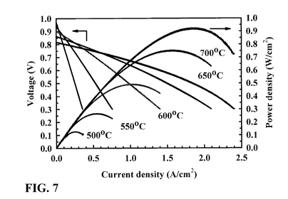
[0034] FIG. 7 is a graph showing current-voltage and power density
characteristics for the fuel cell consisting of button cell of FIG. 4 on which
a
samarium strontium cobaltite cathode is applied operated at temperatures
between 500 and 700 C;
7
CA 02715770 2010-08-17
WO 2009/105886 PCT/CA2009/000236
[0035] FIG. 8 is a scanning electron micrograph taken at a 500 times
magnification of a cross-section of a SOFC fuel cell of FIG. 7 after
performance and thermal cycle testing (14 cycles between 25 C and 600 C at
60 C/min heating rate);
[0036] FIG. 9 is a top-view photograph of a circular SOFC button cell fuel
cell component with a diameter of 16 mm, 1.25 mm thick, consisting of a
Hastelloy X substrate, a nickel oxide-SDC anode and a SDC electrolyte
produced by suspension plasma spraying;
[0037] FIG. 10 is a scanning electron micrograph taken at a 1,000 times of
a cross-section of the button cell shown in FIG. 9;
[0038] FIG. 11 is a scanning electron micrograph taken at a 5,000 times
magnification of the cross-section of the button cell shown in FIG. 9;
[0039] FIG. 12 is a graph showing current-voltage and power density
characteristics for the fuel cell consisting of the button cell shown in FIG.
9
covered with a samarium strontium cobaltite cathode operated at
temperatures between 400 C and 700 C with hydrogen and air;
[0040] FIG. 13 is a scanning electron micrograph taken at a 150 times
magnification of the cross-section of a fuel cell of FIG. 12 after performance
and thermal cycle testing;
[0041] FIG. 14 is a graph of particle states in a spray jet as a function of
standoff in terms of SDC particle temperature and velocity in a HVOF thermal
spray apparatus using suboptimal parameters in comparison with those of
FIG. 2;
[0042] FIG. 15 is a scanning electron micrograph taken at a 5,000 times
magnification of the cross-section of a SDC coating on a stainless steel 430
substrate;
[0043] FIG. 16 is a scanning electron micrograph taken at a 500 times
magnification of the cross-section of a SDC coating on a stainless steel 430
substrate;
8
CA 02715770 2010-08-17
WO 2009/105886 PCT/CA2009/000236
[0044] FIG. 17 is a scanning electron micrograph taken at a 10,000 times
magnification of the cross-section of a SDC coating produced with submicron
sized particles on a mild steel substrate; and
[0045] FIG. 18 is a scanning electron micrograph taken at a 1,000 times
magnification of the cross-section of the SDC coating shown in FIG. 17.
Description of Preferred Embodiments
[0046] It has been surprisingly found that injecting submicron- to nano-
sized ceria-containing particles suspended in a combustible organic solvent
into a plume having a temperature between about 2,600 C and 4,000 C
produces a thin, uniform, dense, crack-free, nanocrystalline ceria-based
coating, which may be applied on porous cermet or metal substrate, for
example. The plume within this temperature range preferably imparts onto a
resulting spray jet a mean temperature of from about 2,600 C to about
3,800 C which has been demonstrated to sufficiently melt a substantial
proportion of the particles, and to accelerate the particles to a mean
velocity
between about 600 to 1000 m/s. The physical environment of a high-velocity
oxy-fuel (HVOF) thermal spraying gun suitably deployed using standard fuels
produces these conditions. The method of the present invention is particularly
useful for the cost-effective fabrication of ceria-containing electrolytes for
solid
oxide fuel cells (SOFCs).
[0047] While not wanting to be limited by the following theory, it is
postulated that the relatively low temperatures of the spray jet in the range
of
2,600-3,800 C, barely above or below the melting point of pure ceria,
sufficiently melted enough of the of spray jet to permit decent deposition
rates
because of substantial contributions from at least some of the following:
dopants such as Nb, Ta, Gd, and Sm are known to reduce the melting point of
the ceria by different amounts in comparison with pure ceria; the relatively
high surface area of the particles provides a relatively large thermal
interface
for exchanging heat with the plume, in comparison with larger particles; the
small volume of the particles permits less heat to completely melt the
particles; the size of the particles may further reduce the intrinsic melting
point
9
CA 02715770 2010-08-17
WO 2009/105886 PCT/CA2009/000236
of the particles in comparison with that of the bulk material according to the
quantum size effect; the combustible organic solvent intimately in contact
with
the particles burns to supply a heat greater than the latent heat of
vaporization
and accordingly supplies localized heat to the particles; and the length of
the
plume extending substantially from the combustion chamber to the substrate
provides for reduced cooling times after the spray jet exits the plume and a
prolonged entrainment within the plume.
[0048] The examples below demonstrate a reproducible, relatively high
deposition rate, thermal spray process using the identified thermal regime.
[0049] While advances in thermal spray technologies are ongoing, and
while plasma plumes can be made exceedingly hot, it is noted that they
generally have very small (a few centimeters) spatial extent (unless produced
in a vacuum), and accordingly it has not been found possible to heat a spray
jet to an average temperature of 2,600-3,800 C with a plasma torch, nor has it
been found possible to operate a plasma torch having a maximum
temperature of 2,600-4,000 C. The HVOF gun used in the examples has a
plume extending from a combustion chamber through a barrel and beyond,
having a spatial extent of at least 20 cm.
[0050] It has surprisingly been found that high density (low porosity) and
highly uniform, thin, ceria-based coatings can be applied without traversal
cracks or pin holes (i.e. breaks in the coating that run in a direction
substantially normal to the substrate surface) that may occur with the
deposition of the particles using plasma spraying. While not wanting to be
limited by the following explanation for this coating property is posited.
[0051] The relatively low temperatures of the spray jet in accordance with
the present invention, permits a fraction of the spray jet to not
substantially
melt. The high velocities of this insufficiently melted fraction arrive at the
substrate/coating and serve to peen the surface. This peening provides local
plastic deformation of the cooling coating, which is considered to have
significant effects on the intrinsic stresses in the coating. The shrinkage of
the
coating material due to solidification and thermal contraction during cooling,
CA 02715770 2010-08-17
WO 2009/105886 PCT/CA2009/000236
which is understood to lead to the detrimental crack formation in the coating,
is compensated by this plastic deformation. Evidence of the peening is
provided by the smoothness of the coating surface akin to grit blasting. The
insufficiently molten fraction appears to need to be limited to ensure
adherence as if the fraction is too high (i.e. the mean temperature of these
particles is too low) the coating is effectively grit blasted resulting in the
effacement of the coating at a rate that approaches the rate of deposition.
[0052] Furthermore it is believed that overheating of ceria-based powders
(i.e. heating to temperatures near their boiling point) have numerous
consequences, as explained by S. Sodeoka et al. in a paper entitled "Thermal
and mechanical properties of Zr02-CeO2 plasma-sprayed coatings" (Journal
of Thermal Spray Technology, Vol.6 (3) 1997, 361-367). If ceria-based
materials are exposed to high temperatures, chemical reduction of the cerium
from Ce4+ to Ce+3 can occur through the loss of oxygen, resulting in the
formation of Ce203 along with the typically strongly reducing atmosphere in a
plasma plume. Ce203 is an electrically conducting material, which is known to
reduce the performance of the electrolyte. Ce203 is somewhat fragile and
occupies a different specific volume than CeO2, and can therefore interfere
with the mechanical integrity and uniformity of the coating. Moreover, as
Ce203 melts at 1,690 C (whereas CeO2 melts at about 2,750 C), Ce203 also
evaporates at substantially lower temperature than CeO2. The overheating in
the plasma flame may then causes a non-negligible portion of the ceria to
evaporate, which reduces the deposition efficiency.
[0053] Furthermore, the plumes of plasma torches are strongly reducing
environments that encourage the stripping of oxygen from the particles. The
plume is therefore preferably a much less reducing environment. Fortunately
the HVOF gun can even operate with a surplus of oxygen relative to that
consumed by the fuel(s) combustion to inhibit the reduction reaction.
[0054] In any case, it has been found that using flames having maximum
temperatures below 4,000 C, and more preferably below 3,800, 3,500, 3,300,
or 3,200 C results in good quality coatings.
11
CA 02715770 2010-08-17
WO 2009/105886 PCT/CA2009/000236
[0055] FIG. 1 schematically illustrates an apparatus useful for applying the
process of the present invention. The design and equipment choice is
principally dedicated to deliver a uniformly dispersed submicron- to nano-
scale ceria particle suspension feedstock to a plume having a temperature
between about 2,600 C and about 3,500 C at a precise rate, in which the
particles are heated and accelerated, and to avoid any malfunction of the
equipment due to the suspension feedstock. The apparatus includes a
torch 1, which may be commercially available HVOF gun, to which a fuel
supply 2, for supplying a liquid fuel such as kerosene and propylene, or a
gaseous fuel such as ethylene, propane or hydrogen, oxygen supply 3 and air
supply 4 are delivered. The fuel supply 2, oxygen supply 3 and pressurized
air supply 4 lead to a combustion chamber 5 where the fuel is ignited to form
a high-velocity super-sonic combustion flame 6, which provides the plume in
the illustrated embodiment.
[0056] The suspension feedstock is supplied to the combustion chamber 5
though a suspension supply tube 7 concentrically enclosed by an annular
coolant feed tube 9. The outer diameter of the suspension supply tube 7 may
be chosen to fit inside a standard powder feeding tube of a standard
commercially available torch. The coolant feed tube 9 supplies an inert gas
such as N2 to the combustion chamber. The inert gas serves to cool the
suspension injection tube and gas distributor of the torch 1 and to control
properties of the torch I during operation.
[0057] The suspension is propelled into the combustion chamber 5 under
fluid pressures, where the organic carrier combusts with the oxygen and fuel
and the solid content of the suspension is precipitated into small particles,
which tend to melt or partially melt while in contact with the flame 6, and
are
accelerated to form a spray jet. The combustion chamber 5 is in fluid
communication with a barrel 16 which exits the torch 1 at a nozzle. The
flame's 6 confinement to the combustion chamber 5 and the barrel 16 leads to
an extended travel time during which the spray jet is heated and accelerated.
When the burning gasses are ejected through the nozzle, combustion is
continuing and the flame is traveling at a substantial velocity, carrying the
12
CA 02715770 2010-08-17
WO 2009/105886 PCT/CA2009/000236
spray jet. The duration of the particles within the flame may permit the
particles to nearly match the temperature of the flame.
[0058] The spray jet of heated and accelerated particles impact on the
substrate 10 to form the coating 11. The mean temperature of the particles is
substantially at or somewhat above the melting point of the ceria used, and is
not overheated prior to contact with the surface.
[0059] The spray jet continues to be heated while it remains in the plume
of a thermal spray apparatus, and rapidly cools thereafter. The combustion
flame of an HVOF gun therefore provides for heating from the point the
suspension is fed into the chamber throughout the acceleration through the
barrel, and after discharge throughout the length of the projected flame. The
flame of the spray jet can extend up to 30 cm from the nozzle of the HVOF
gun. In contrast, plasma plumes are very small, extending only a few cm from
the nozzle. Throughout the travel between the end of the plume and the
substrate, the particles rapidly cool. In order for the spray jet to retain
sufficient heat to remain sufficiently molten upon striking the substrate to
produce a coating, the spray jet must be overheated in the plume, which is
problematic for ceria-based coatings. For the same reason, the substrate has
to be placed close to the plasma flame (plume) to reduce the travel time of
the
spray jet available for cooling and deceleration.
[0060] Consequently using an HVOF gun, instead of the plasma torch, the
standoff distance between the exit of the barrel of the torch I and the
substrate 10 can be significantly longer. This permits the spray jet to be
deposited at a temperature and velocity that may be nearly maximal, rather
than in close proximity to the high intensity heat source of a plasma. Using
the HVOF gun may improve deposition efficiency and coating quality. In any
case, it has been found that the particles are preferably deposited on the
substrate at a standoff where the mean velocity in the spray jet would
otherwise be above 600 m/s. Depending chiefly on the size distribution and
composition of the ceria-based particles, a temperature of at least 2,600 C is
required in order to achieve a good deposition efficiency and coating quality.
13
CA 02715770 2010-08-17
WO 2009/105886 PCT/CA2009/000236
More preferably, especially if SDC is used, a temperature above 2750 C
would be preferred.
[0061] FIG. 1 also shows a feed delivery apparatus consisting of a
suspension vessel 12, which is equipped with an agitator 13 to prevent
sedimentation in the vessel and ensure homogeneity of the solid content, a
flow measurement and dosing system 14, and a washing system 15. While it
is widely known that nanoparticles have a tendency to aggregate and it is
known that monodispersion is an exceedingly difficult condition to obtain, in
general the higher the uniformity of distribution of the nanoparticles in the
suspension, the more uniform the delivery, and the more likely that smaller
volume precipitates will be produced by the atomization and solvent
evaporation within the chamber. Accordingly the spray jet will include more of
the smaller, more fully melted droplets which are entrained in the combustion
flame, and are believed to be essential to providing the deposition efficiency
and coating quality.
[0062] Given the theory posited above, it is reasonable to infer that a size
distribution of the powder that is substantially bimodal, with a substantial
part
being nanoscale powders less than 50 nm and more preferably less than
about 30 nm or 20 nm as is used below would provide the substantially
molten droplets that provide the adhesion and larger diameter fraction that is
expected to substantially peen the substrate or impact the substrate with a
higher inertia to densify the coating. The larger fraction may be constituted
of
monolithic nano- to submicron-scale particles, or may be nanostructured
agglomerates. In the later case a higher surface area to volume ratio would
be expected favouring increased probabilities of sufficient melting and
incorporation of the larger fraction into the coating in comparison with the
former, which would increase a deposition efficiency.
[0063] Naturally the combustion chamber produces a considerable
pressure. The delivery of each fluid to the combustion chamber must
overbear this pressure, while maintaining controlled delivery, including the
suspension. This can be achieved by using pump based systems such as
that described in Applicant's US application serial no. 11/410,046 and
14
CA 02715770 2010-08-17
WO 2009/105886 PCT/CA2009/000236
International Patent Application PCT/CA2006/000651, or by pressurizing the
feedstock to a pressure higher than that of the combustion chamber, as
described in the paper to Killinger et al. identified above, the totality of
which
is incorporated herein by reference. In the examples provided, the method of
Killinger et al. is adopted, using essentially a Nanofeed Liquid Powder Feeder
Model 650 from Northwest Mettech Corp. (North Vancouver, BC, Canada).
[0064] Suspension delivery systems are able to deliver with feed rates
between 0.01 and 10 kg/hr, and to maintain constant and adjustable feed
rates for the duration of a coating process. Such delivery systems may be
fully automated and have automated washing and rinsing cycles to clean the
delivery lines in between deposition runs. Furthermore, the suspension
delivery system can provide the preferred suspension feed rate of 0.5 kg/hr to
kg/hr, more preferrably 1.5 kg/hr to 2.5 kg/hr against the backpressure in the
combustion chamber, which can reach or exceed 100 psi.
[0065] In operation, HVOF thermal spray guns are known to use either
liquid fuel such as kerosene and propylene, or gaseous fuel such as ethylene,
propane or hydrogen to combust with pure oxygen and air at flame
temperatures between 2,500 C and 3,200 C. Suspended feedstock particles
injected into the combustion chamber are precipitated out by the vaporization
and combustion of the combustible organic solvent to produce a spray jet that
is heated and melted while accelerating with the plume to exit the gun nozzle
at high velocities.
[0066] The spray jet then impact on a substrate that is usually positioned
substantially orthogonally to the velocity of the spray jet at some distance
(standoff) downstream from the gun exit nozzle to form the thermal spray
coating. Maximum temperatures of the particles in the HVOF spray process
depends on the spray gun design as well as on the feed rate, morphology and
size distribution of the powder particles, oxygen to fuel ratio as well as
position within the spray flame.
[0067] It should be pointed out that for HVOF spraying of submicron- to
nano-sized ceria particles in accordance with the invention, the maximum
CA 02715770 2010-08-17
WO 2009/105886 PCT/CA2009/000236
particle temperature (e.g. between 2750 C and 3300 C) is reached outside
and downstream from the gun exit nozzle, such that the particle can be
deposited on the substrate in or close to their hottest state during their
flight
history. A fortiori no earlier overheating has taken place.
[0068] It should further be pointed out that for HVOF spraying of
submicron- to nano-sized ceria particles in accordance with the invention, the
particles are accelerated to high velocities above 600 m/sec, reaching 700-
1000 m/sec close to the gun exit nozzle.
[0069] Feeding submicron or nano-sized particles into a thermal spray gun
with conventional powder feeding equipment is known to be difficult or
impossible due to the strong powder agglomeration, which impedes powder
flowability. Suspending the small particles in a liquid carrier, which is then
injected into the HVOF gun, and can therefore alleviate this problem and
allows for more precisely controlled feeding rates of the feedstock.
[0070] Ceria-containing electrolyte coatings according to the invention are
produced from suspended ceria-containing submicron- to nano-sized
particles, which may have a mean particle size below about 100 nm,
preferably below about 60 nm, more preferably below about 20 nm,
corresponding to a specific surface above 80 to 220 m2/g. The particles are
composed of cerium oxide, preferably doped or admixed with another oxide to
enhance the ionic conductivity. For example, Nb, Ta, Gd, Sm, Y, Ca, or Sr
and preferably gadolinium oxide or samarium oxide may be used. Examples
of compositions of solid electrolytes having oxide-ionic conduction includes
(Ce02)0.8(YO1.5)0.2; (Ce02)0.9(Sm01.5)0.1; (Ce02)0.8(CaO)0.2;
(Ce02)0.8(SrO)0.2.
The ceria-based powder has a general formula of (Ce02)1_),(Sm01.5))', where x
is preferably about 5-25 mol%, more preferably 15-20 mol%. A commercially
available example of a suitable nano-sized powder is produced by nGimat
TM, Atlanta Ga, USA.
[0071] Using a combustible organic solvent carrier, such as for example
ethanol or ethylene glycol or a mixture of ethanol and ethylene glycol, into
which the nano-sized particles are suspended, additional fuel for the
16
CA 02715770 2010-08-17
WO 2009/105886 PCT/CA2009/000236
combustion in the HVOF gun is provided to further increase the particle
temperatures. The powders according to the invention are suspended in a
combustible organic solvent, which may be ethanol, ethylene glycol or the
like. Two or more solvents can be mixed. As such, the solvent poses a low
thermal load on the flame, or even contributes to its heat. The ethylene
glycol
appears to chemically disperse the powders used, especially when included
at about 75%.
[0072] The suspensions may be prepared with a mixture of less than 20
solid wt. %, preferably less than 5 wt. %, and in the best example 2 and 3 wt.
% of solids is used, ensuring only small amounts of molten ceramic exit the
gun at a time, which has been observed to increase the average particle
temperature and to be beneficial for the coating formation.
[0073] To prevent solid sedimentation, the suspensions can be prepared
using any one of a wide variety of dispersants. The person of ordinary skill
in
the art will choose a dispersant a view to optimally dispersing the particles
in
the particular organic solvent used. For example, polyethyleneimine, available
by Alfa Aesar, USA could be used because a cationic polyelectrolyte was
found to work in this system.
[0074] The coating can be applied in a wide range of thicknesses. For use
in a SOFC, the thickness is preferably less than 100 pm, more preferably less
than 80 pm, more preferably less than 70, 60, or 50 pm. Coatings have been
produced with about 20 pm thicknesses. Uniform thickness coatings of
between 5 and 25 pm are contemplated by variation of the parameters to
provide a favourable SOFC electrolyte. A thin and nanostructured electrolyte
layer can compensate for the reduction of ionic conductivity at lower
temperatures by decreasing the traveling distance of oxygen ions and
enhancing the mobility of the ions along the grain boundaries. Since the
electrolyte thickness is inversely proportional to the oxygen ion flux through
the electrolyte, the thin electrolyte has the advantage of lower ohmic
resistance during cell operation.
17
CA 02715770 2010-08-17
WO 2009/105886 PCT/CA2009/000236
[0075] The electrolyte should have no open porosity and a closed porosity
below 1%, and preferably below 0.5%, to reduce gas leakage across the
layer. Furthermore the electrolyte should have virtually no cracks that permit
reactant gases to pass through the electrolyte during operation of the cell.
Gas tightness is important to attain a high voltage of the cell and reduce
degradation due to hot regions created by the combustion of gases which
would pass through cracks or pinholes in the electrolyte during operation of
the fuel cell. For example, a gas leakage rate measured with Helium gas at 1
psi differential pressure across the electrolyte area should be below 0.15
L/min/cm2, preferably below 0.1 L/min/cm2.
[0076] While the examples and parameters below are all provided using a
particular HVOF gun, it will be appreciated that the person of ordinary skill
in
the art will be able to achieve equivalent results using analogous equipment
with corresponding operating parameters to achieve flames within the
temperature range provided to impart the desired temperature and velocity to
the sub-micron to nano-sized particles.
[0077] The following non-limiting examples demonstrate the method for the
production of the ceria-based coating and show its performance as an
electrolyte for a reduced temperature SOFC.
Example 1: HVOF sprayed electrolyte
Apparatus
[0078] A thermal spray apparatus, as shown in FIG. 1 was assembled. A
commercially available HVOF gun used (model number DJ-2700, Sulzer-
Metco, Westbury, NY, USA) is capable of generating supersonic flame
velocities and sufficiently high temperatures.
[0079] The DJ-2700 gun has a stainless steel tube inserted into the 1.5
mm inner diameter feedstock supply tube throughout its length so that the
stainless steel tube had an opening flush with the opening of the feedstock
supply tube at the combustion chamber. The stainless steel tube was a 19
gauge tube having an outer diameter just over 1 mm, and an inner diameter of
18
CA 02715770 2010-08-17
WO 2009/105886 PCT/CA2009/000236
about 0.8 mm, although other arrangements that do not provide excessive
resistance to both the coolant and the feedstock suspension flows would be
expected to work equally well. This is how the inert gas and feedstock
suspension were supplied to the DJ-2700 gun.
[0080] The suspension of 2.5 wt. % solids in a 3:1 mixture of ethylene
glycol to ethanol was prepared from nanosized (-20 nm particle size)
samarium doped ceria (SDC) (specifically (Ce02).8(SmO1.5).2) and dispersed
in a two-frequency ultrasonic bath at 16 and 80 kHz, with the addition of a
dispersant at a quantity corresponding to 0.5 wt% of powder
polyethyleneimine, obtained from Alfa Aesar, USA. The suspension was
mechanically agitated for at least 12 hrs. The suspension was injected into
the
DJ-2700 at a flow rate of 33.3 mL/min with a computer controlled flow control
loop from a pressurized canister maintained at a pressure of 150 psi.
[0081] Experimental conditions were as follows:
Propylene flow 75 slpm
Oxygen flow 279 slpm
Air flow (shroud) 202 slpm
Nitrogen flow 15 slpm
Spray jet particle ranking
[0082] On-line measurements of the particle states in the spray jet were
performed using commercially available particle diagnostic equipment
(Accuraspray G3, Tecnar Automation, St. Bruno, Quebec, Canada).
[0083] These measurements indicated that the highest average particle
temperature (2980 100 C) was reached with a standoff distance of between
about 14 and 16 cm from the gun exit nozzle where the average particle
velocity slows to about 700-600 m/sec.
[0084] FIG. 2 is a graph that shows the average particle velocity and
temperature as a function of standoff. The graph illustrates that indeed the
highest particle temperature is attained downstream of the gun exit nozzle.
Based on this measurement, a standoff distance of 127 mm was chosen for a
19
CA 02715770 2010-08-17
WO 2009/105886 PCT/CA2009/000236
substrate. The 127 mm standoff distance was particularly chosen because it
is about 2.5 cm before the maximum temperature standoff.
[0085] The flame properties at a given standoff and thus the spray jet
properties are altered significantly by the presence of the substrate. The
sheath gas, spray jet and plume are all affected by the obstacle. The gasses
are entirely deflected. As the precipitated solids are light enough to be
entrained by the gas in order to produce the spray jet in the first place, a
significant part of the spray jet will slow significantly (in the direction of
the
surface normal) and lose heat in the process. For this reason a sufficient
inertia to the spray jet is important to permit these to land on the surface
of the
coating/substrate.
[0086] A minimum velocity of about 600 m/s is considered important for
ensuring deposition at a high enough rate to provide a coating in accordance
with this invention. It is expected that a standoff distance between 11.5 cm
and 16 cm could be used to achieve substantially similar coatings, as shorter
standoff distances would provide particles that aren't hot enough (for these
particles so dispersed and sized), and would also increase thermal stresses
on the substrate, and any longer standoff distances would not provide
sufficient inertia to strike the substrate.
[0087] It should be noted that the temperature trend is more accurately
identified than the absolute temperatures measured using this equipment.
The trend is confirmed by the deposition rates at standoff distances that are
close to the maximum temperatures attained, which must be at or above the
melting point of the particles. The maximum mean temperature of the spray
jet was observed to be 2980 C +/- 100 C.
[0088] It should further be noted that the graph shows only the points that
are well suited to the deposition of SDC of a particle size distribution of
than
20 nm in the apparatus under the illustrated mode of operation. A
hotter/cooler fuel, different fuel delivery rate, smaller mean particle size,
or a
different dopant will be expected to change the mean temperature of the
particles required for deposition. It is believed that useful deposition rates
can
CA 02715770 2010-08-17
WO 2009/105886 PCT/CA2009/000236
be achieved with finer sized doped particles at temperatures as low as 2,600,
and that useful coatings can be provided by raising the temperatures of the
particles as high as 3,800, for example, if larger particles of undoped ceria
are
used.
Sample preparation
[0089] A SDC electrolyte of approximately 20 pm thickness was deposited
on a porous, 70 micron thick suspension plasma sprayed anode, composed of
50 wt. % nickel-oxide and 50% wt. SDC. The electrolyte can also be
deposited onto an air electrode and used in a planar or tubular fuel cell, for
example. The anode, in turn, was supported by a metallic Hastelloy X
substrate with a porosity of 27.5% and a pore size of about 10 pm. The
electrolyte was produced using the DJ-2700 and apparatus as described
above.
[0090] The substrate was retained on a cooled substrate holder adapted to
the substrate dimensions. The substrate holder was a planar plate having
dimensions substantially larger than the substrate and the spray jet,
combustion flame, and sheath gasses so that an obstruction of an infinite
plane is presented. During deposition, the substrate temperature was
maintained at about 450 C using backside air and water cooling, as well as
forced-air cooling at the front side of the substrate holder.
[0091] To deposit the coating, the gun was moved in a ladder pattern in
2.5 mm steps horizontal to the substrate at a scan speed of 760 mm/second
and repeated 60 times, i.e. 60 passes at the standoff distance of 127 mm from
the substrate.
[0092] In this manner, a substrate having a circular disk geometry of 16
mm diameter was coated. Electrolyte coatings were also produced on larger
substrates with rectangular dimensions of 50 X 50 mm without introducing any
distortion of the substrate during spraying or any optically visible defect in
the
electrolyte coating. For the larger 50 X 50 mm substrates, the electrolyte
coating was produced in 16 minutes, consuming 13.3 g of (solids) SDC
21
CA 02715770 2010-08-17
WO 2009/105886 PCT/CA2009/000236
powder material. A deposition efficiency of approximately 50% was attained.
FIG. 3 is a photograph of the 50 X 50 mm half-cell after electrolyte
deposition.
Micrographic imaging
[0093] FIGs. 4 and 5 are micrograph images of the button cell of example
1 showing the uniform microstructure of the electrolyte layer taken at 50 and
500 times magnification, respectively. The cross-section was obtained by
vaccum impregnating the sample with epoxy, dicing the impregnated button
cell with a metallurgical diamond blade saw, mounting the sample in an epoxy
disk and then polishing the cross-section with consecutively refining
polishing
media up to 0.05 micron diamond paste.
[0094] The electrolyte has a thickness between 60 and 75 microns, and is
of very uniform thickness, given the roughness of the substrate. The
electrolyte has no major defects and has a relatively smooth surface finish,
which facilitates further processing steps, such as the subsequent deposition
of an air electrode. The electrolyte layer material appears well fused, and no
distinct lamellar structure can be discerned. The electrolyte layer is in
close
contact with the rough surface of the underlying fuel electrode thereby
ensuring sufficient electrical contact and adhesion.
[0095] Electron microscopy on the cross-section of the coatings revealed a
highly dense micostructure, free of cracks and without any visible lamellar
structure, as shown in FIG. 5. A pronounced lamellar structure is usually
associated with thermal spray coatings by virtue of the overlapping droplets
from which it is formed. A porosity < 1 % was determined using image analysis
on the micrograph. Besides some closed porosity, the micrograph in FIG.5
shows only few regions of gray contrast, which are representative of pull-out
and fracture surface created during the polishing step. This serves as an
indication of a high degree of material fusion and coating quality.
X-Ray analysis
[0096] X-Ray Diffraction (XRD) analysis indicated that the coatings
consisted exclusively of cerianite (CeO2) of a fluorite crystalline structure.
The
22
CA 02715770 2010-08-17
WO 2009/105886 PCT/CA2009/000236
nanostructure of the coatings was confirmed by the peak broadening of the
XRD spectra, indicating a grain size of below 50 nm. An exemplary XRD
spectrum is depicted in FIG. 6.
Gas tightness testing
[0097] Gas tightness is important to attain a high voltage of the cell and
reduce degradation due to hot regions created by the combustion of gases
which would pass through cracks or pinholes in the electrolyte during
operation of the fuel cell. A gas leakage rate measured with Helium gas at 1
psi differential pressure should be below 0.15 slpm, preferably below 0.1
slpm.
[0098] The produced half cells (metal interconnect-anode-electrolyte) were
subjected to a gas leak test, using helium at 1 psi differential pressure. In
this
rest the cell is sealed on the electrolyte, using o-rings, and helium pressure
is
applied to one side, while the gas flow through the electrolyte is recorded by
a
mass flowmeter. The electrolyte had a measured low gas permeability of
0.085 slpm/cm2.
SOFC construction
[0099] After electrolyte deposition, a composite cathode consisting of
samarium strontium cobaltite (SSCo) and SDC (70 wt% SSCo) was applied to
the electrolyte by stencil printing. The composite cathode was in situ fired
at
800 C for 2 h. NiO-SDC anode was reduced at 650 C with 10% H2 (Nitrogen
as balance gas) for 90 min, 20% H2 for 60 min, 50% H2 for 30 mins, 100% H2
for 120 mins. All the mixed gas was humidified at room temperature.
SOFC performance
[0100] The button cell performance and electrochemical impedance
spectra were tested from 500 C to 700 C in 50 C intervals.
[0101] Exemplary performance of this button cell is shown in FIG. 7. A
maximum power density of The 0.92 W/cm2 at 700 C was attained. At 600 C
the cell shows a maximum power density of 0.5 W/cm2. This is an
23
CA 02715770 2010-08-17
WO 2009/105886 PCT/CA2009/000236
exceptionally high value for a metal supported SOFC operated at reduced
temperatures and underscores the quality of the coating.
Thermal cycling
[0102] The button cell was thermally cycled between 60 C and 600 C at a
60 C/min heating rate for 14 cycles.
[0103] After cycling the microstructure of the electrolyte of the fuel cell is
substantially unaltered as shown in the micrograph of FIG. 8. On the other
hand, changes in the anode and cathode microstructure, as well as at the
interface between the components lead to significant performance
degradation of the SOFC.
Example 2: Plasma sprayed electrolyte
Apparatus
[0104] In this example, a SDC electrolyte of approximately 27 pm
thickness was fabricated by suspension plasma spraying using an axial
injection plasma torch (Axial III, Northwest Mettech Corp., North Vancouver,
BC, CAN). The SDC electrolyte was deposited onto a porous, 25 micron thick
suspension plasma sprayed anode, composed of 70 wt. % nickel-oxide and
30 wt. % SDC. The anode, in turn, was supported by a metallic Hastelloy X
substrate with a porosity of 27.5% and a mean pore size of about 10 pm. As
such the electrolyte is applied to a comparable surface as that of the
electrolyte of example 1.
[0105] This example was first published in Dynamic Evaluation Of Low-
Temperature Metal-Supported Solid Oxide Fuel Cell Oriented Towards
Auxiliary Power Units (Z. Wang et al., Journal of Power Sources, Vol. 176,
Issue 1, Jan. 2008, 90-95).
[0106] For the electrolyte, the suspension of 5 wt % solids in ethanol was
prepared from micron to sub-micron sized SDC particles (average particle
diameter d50 < 1.54 pm), and dispersed in a two-frequency ultrasonic bath at
16 and 80 kHz, with the addition of a dispersant. The suspension was injected
24
CA 02715770 2010-08-17
WO 2009/105886 PCT/CA2009/000236
into the center of three converging plasma streams inside the torch at a flow
rate of 21.7 mL/min.
[0107] In such an arrangement, the suspension droplets are intimately
contacted with the plasma flame (8000 C- 15,O00 C) to impart a high heat
and momentum transfer, which was found to be beneficial for creating the
densest and most defect free coatings. During deposition, the substrate
surface temperature was maintained below 700 C using backside air and
water cooling, as well as forced-air cooling at the front side. Plasma torch
operating conditions were as follows:
Torch current (3X) 200 A
Total primary gas flow rate 275 slpm
Argon concentration 75 %
Nitrogen concentration 15 %
Hydrogen concentration 10 %
Torch power 91 kW
Torch nozzle size 9.53 mm
[0108] To apply the coating, the torch was moved in a ladder pattern in 3
mm steps horizontal to the substrate at a scan speed of 1016 mm/second and
repeated 140 times, i.e. 140 passes at a standoff distance of 50.8 mm from
the substrate.
[0109] The substrate had circular disk geometry of 16 mm diameter (button
cell). The electrolyte coating was produced in 16 minutes, consuming 17.3 g
of SDC powder material. A deposition efficiency of approximately 15% was
attained.
[0110] The following differences between how the electrolytes were
deposited in the first and second examples are noted: the change in the
combustible organic solvent is expected to have little consequence in terms of
the temperature of the plume because of the extremely high temperatures in
the plasma torch, but is expected to impact the feedstock properties and in
particular the uniformity of the dispersion, which are not expected to be as
critical in the plasma thermal spray embodiment; the differences in scan
CA 02715770 2010-08-17
WO 2009/105886 PCT/CA2009/000236
speed and number of passes are also not expected to significantly impact on
the quality of the electrolyte. The low deposition efficiency is the highest
that
was achieved, and using a smaller particle distribution, resulted in a lower
deposition efficiency, as is consistent with the premise that Ce203 is
vaporized
in the process.
[0111] FIG. 9 shows a photograph of a button cell-cell after electrolyte
deposition.
Spray jet particle ranking
[0112] Prior to spraying the coating, on-line measurements of the particle
states were performed using commercially available particle diagnostic
equipment (Accuraspray G3, Tecnar Automation, St. Bruno, Quebec,
Canada). The measurement volume was centered in the spray plume at the
location of the substrate during deposition, at the standoff distance of 50.8
mm. Due to interference with the optical diagnostic system by the output of
the plasma torch, an indirect approach to ranking the particle states was
adopted, using zirconia suspensions at the same spray conditions. An
average in-flight particle velocity of 860 m/sec and temperature of 2950 C
was determined at the spray distance of 50.8 mm.
Micrographic imaging
[0113] Electron microscopy on the cross-section of the coatings revealed a
relatively dense microstructure, with some residual fine porosity and a few
thin
vertical defects, as shown in FIG. 10. A porosity as high as 2% was
determined using image analysis on the micrograph. Besides some porosity,
the micrograph in FIG. 11 shows some regions of gray contrast, which are
representative of pull-out and fracture surface created during the polishing
step. This can serve as an indication of some incomplete material fusion.
Gas tightness testing
26
CA 02715770 2010-08-17
WO 2009/105886 PCT/CA2009/000236
[0114] The produced half cells (metal interconnect-anode-electrolyte) were
subject to a gas leak test, using helium at 1 psi differential pressure and
showing a low gas permeability of 0.37 slpm/cm2.
SOFC construction
[0115] After electrolyte deposition, a composite cathode consisting of
samarium strontium cobaltite (SSCo) and SDC (75 wt% SSCo) was applied to
the electrolyte by screen printing. The composite cathode was in situ fired at
800 C for 2 h. NiO-SDC anode was reduced at 650 C for 5h while gradually
introducing hydrogen. All the mixed gas was humidified at room temperature.
SOFC performance
[0116] The cell performance and electrochemical impedance spectra were
tested from 400 C to 700 C in 50 C intervals.
[0117] Cell performance is graphically represented in FIG. 12. A maximum
power density (MPD) of 0.216 W/cm2 with an open cell voltage (OCV) of
0.768 at 650 C was attained. At 600 C, the cell showed a MPD of 1.76
W/cm2. At 700 C the cell showed a MPD of 0.183 W/cm2. This performance is
within the range of values reported for metal-supported SOFCs at the current
state of the art. In comparison, example 1 provides 2-5 times the power
density at the corresponding operating temperatures.
[0118] Having regard to the examples 1 and 2, it is surprising that such a
significant change in the quality of the electrolyte and the material
properties
of the coating could be achieved by reducing the temperature of the thermally
sprayed particles to near that of the melting point of the ceria-based
particles.
Themal cycling tests
[0119] The SOFC was thermally cycled between 60 C and 600 C at a
60 C/min heating rate for 12 cycles.
[0120] After cycling the microstructure of the fuel cell electrolyte is
substantially unaltered as shown in the micrograph of FIG. 13. For much the
27
CA 02715770 2010-08-17
WO 2009/105886 PCT/CA2009/000236
same reasons as stated in relation to example 1, the SOFC performance was
degraded by the thermal cycling.
Example 3: Suboptimal fuel to oxygen ratio
[0121] A SDC coating of approximately 15 pm thickness was deposited on
a stainless steel 430 substrate. For the coating, the suspension of 5 wt. %
solids in ethanol was prepared from nanosized SDC (-20 nm particle size).
The suspension was injected into the DJ 2700 spray gun at a flow rate of 50
mL/min. During deposition, the substrate temperature was maintained at
420 C using backside air and water cooling, as well as forced-air cooling at
the front side. Experimental conditions were the following:
i. Propylene flow 80 slpm
ii. Oxygen flow 279 slpm
iii. Air flow (shroud) 202 slpm
iv. Nitrogen flow 15 slpm
Spray jet particle ranking
[0122] Prior to spraying the coating, on-line measurements of the particle
states were performed. These measurements indicated that the highest mean
particle temperature of 2670 C 100 C is reached 15 cm after the gun exit
nozzle at an average particle velocity of 660 m/sec. FIG. 14 shows a graph of
the axial profile of average particle velocity and temperature for these spray
conditions. A spray distance of 102 mm was chosen for coating production,
for much the same reason as 127 mm was chosen in example 1.
Electrolyte deposition
[0123] To deposit the coating, the gun was moved in a ladder pattern in
2.5 mm steps horizontal to the substrate at a scan speed of 760 mm/second
and repeated 20 times, at a standoff distance of 102 mm from the substrate.
[0124] The substrate was of the same dimension as for the previous button
cell electrodes of examples 1 and 2, but was a sold stainless steel 430.
Micrographic imaging
28
CA 02715770 2010-08-17
WO 2009/105886 PCT/CA2009/000236
[0125] Electron microscopy of the cross-sections of the coatings revealed
a fractured, non-continuous coating as shown in FIGs. 15 and 16. As such
the coatings are unsuitable for an SOFC electrolyte application. Besides
horizontal cracks, a large number of gray regions can be seen.
[0126] This microstructure indicates that the coating was formed from
particles that were not sufficiently molten at impact to form a continuous
coating. The small amount of deposited material remained on the substrate
only by virtue of mechanical anchoring in the roughness asperities of the
substrate. It is believed that the unacceptably high fraction of
insufficiently
molten particles in the spray jet is responsible for effectively grit blasting
the
surface resulting in a coating that is effaced as fast as it is deposited.
This
conclusion is in agreement with the particle temperatures measured being
below or not sufficiently above the melting point of the ceramic, and below
that of the example 1.
[0127] It is further noted that smaller particle sizes and other ceria-based
compositions are expected to have lower melting points, and accordingly this
thermal spray regime may be useful although the parameters used in example
1, where a substantially higher flame enthalpy is produced, may be preferred
in general because the superheating of the droplets by a small margin (in
comparison with the overheating that approaches the vaporization point of the
ceria-based powder) so that a higher fraction of the spray jet melts in
general
is expected to improve deposition efficiency and coating quality.
[0128] It is therefore noted that too high a delivery rate of the solids
content
in relation to the fuel delivery rate, and a too high fuel delivery rate in
relation
to the oxygen flow, have the consequence of lowering the temperature
imparted on the spray jet, which in this case has a negative impact on the
deposition efficiency, and the quality of the coating.
Example 4: Suboptimal particle size
[0129] A samarium doped ceria coating of approximately 5 pm thickness
was deposited on a mild steel substrate. For the coating, the suspension of 5
wt% solids in ethanol was prepared from sub-micron sized samarium doped
29
CA 02715770 2010-08-17
WO 2009/105886 PCT/CA2009/000236
ceria particles (average particle diameter d50 < 1.54 pm). The suspension
was injected into the HVOF spray gun at a flow rate of 50 ml/min. During
deposition the substrate temperature was maintained at 380 C using forced-
air cooling at the front side. Experimental conditions were as follows:
v. Propylene flow 90 slpm
vi. Oxygen flow 279 slpm
vii. Air flow (shroud) 202 slpm
viii. Nitrogen flow 15 slpm
[0130] To deposit the coating, the gun was moved in a ladder pattern in
2.5 mm steps horizontal to the substrate at a scan speed of 760 mm/second
and repeated 10 times, at a standoff distance of 102 mm from the substrate.
[0131] The substrate had rectangular geometry of 25 X 75 X 12.5 mm.
[0132] A spray distance of 102 mm was chosen for coating production.
[0133] Electron microscopy on a cross-section of the coatings revealed a
microstructure, which appears to be a loose aggregation of particles as shown
in FIGs. 17 and 18. Such coatings are unsuitable for SOFC electrolyte
applications. A large number of gray regions can be seen, which suggest a
lack of particle melting and fusion in the coating. This microstructure
indicates
that the coating was formed from particles that were not sufficiently molten
at
impact to form a continuous coating.
[0134] It is therefore noted that a mean particle size has a significant
impact on the microstructure of the coating. It will be appreciated that the
conditions of examples 3 and 4 are substantially the same except for the
additional fuel in example 4, and the use of a powder having a larger mean
particle size. Despite the added fuel, a significantly worse coating is
produced.
[0135] It will be further noted that the combustible organic solvent used in
examples 3 and 4 did not contain the ethylene glycol and are expected to
accordingly have reduced dispersion of the powder.
CA 02715770 2010-08-17
WO 2009/105886 PCT/CA2009/000236
[0136] While a preferred embodiment has been shown and described,
various modifications and substitutions may be made without departing from
the spirit and scope of the invention. Accordingly, it is to be understood
that
the present invention has been described by way of illustrations and not
limitations.
[0137] References: The contents of the entirety of each of which are
incorporated by this reference.
U.S. PATENT DOCUMENTS
5,672,437 9/1997 Yajima et al.
7,090,891 B2 8/2006 Anderson et al.
6,579,573 B3 6/2003 Strutt et al.
5,609,921 3/1997 Gitzhofer et al.
5,234,722 8/1993 Ito et al.
6,638,575 bl 10/2003 Chen et al.
PATENT APPLICATIONS
US 2005/0089739 Al 4/2005 Seccombe et al.
PCT/CA2006/000651 4/2006 Oberste Berghaus et al.
US2004/0058225 Al 3/2004 Schmidt et al
OTHER PUBLICATIONS
J. Oberste Berghaus, J.-G. Legoux, C. Moreau, R. Hui, D. Ghosh, Suspension
plasma spraying of intermediate temperature SOFC components using an
axial injection dc torch, Material Science Forum, Trans. Tech. Publisher,
Switzerland, Vol. 539-543, (2007) pp. 1332-1337.
J. Oberste Berghaus, J.-G. Legoux, C. Moreau, F. Tarasi, T. Chraska,
Mechanical and thermal transport properties of suspension thermal sprayed
31
CA 02715770 2010-08-17
WO 2009/105886 PCT/CA2009/000236
alumina-zirconia composite coatings, Journal of Thermal Spray Technology,
JTST 17(1) March 2008.
Killinger, M. Kuhn, R. Gadow, High-velocity suspension flame spraying
(HVSFS), a new approach for spraying nanoparticles with hypersonic speed,
Surface & Coatings Technology 2001 (2006) 1922-1929.
R. Gadow, A Killinger, A. Candel Ruiz, H. Weckmann, A. Ollinger, 0. Patz,
Investigation on HVOF-Technique for Fabricatio of SOFCs Electrolyte Layers,
Thermal Spray 2007: Global Coating Solutions, ASM International, Materials
Park, Ohio, USA pp.1052-1058.
Z. Wang, J. Oberste Berghaus, S. Yick, C. Deces-Petit, W. Qu, R. Hui,
R.Maric, D. Ghosh, Dynamic evaluation of low-temperature metal-supported
solid oxide fuel cell oriented to Auxiliary Power Units, Journal of Power
Sources, Vol. 176, Issue 1, Jan. 2008, 90-95.
Q.-A. Huang, J. Oberste-Berghaus, D. Yang, S. Yick, Z. Wang, B. Wang and
R. Hui, Polarization Analysis for Metal-Supported SOFCs from Different
Fabrication Processes Journal of Power Sources, 177 (2008) 339-347.
P. Fauchais, R. Etchart-Salas, C. Delbos, M. Tognonvi, V. Rat, J. F. Coudert
and T. Chartier, Suspension and solution plasma spraying of finely structured
layers: potential application to SOFCs, J. Phys. D: Appl. Phys. 40 (2007)
2394-2406.
J. Will, A. Mitterdorfer, C. Kleinlogel, D. Rerednis, L.J. Gauckler,
Fabrication
of thin electrolytes for second-generation solid oxide fuel cells, Solid State
Ionics 131 (2000) 79-96.
S. Sodeoka, M. Suzuki, K. Ueno, H. Sakamoto, R. Shibata, and M. Ando,
Thermal and mechanical properties of Zr02-CeO2 plasma-sprayed coatings,
Journal of Thermal Spray Technology, Vol.6 (3) 1997, 361-367.
R. Henne, Solid oxide fuel cells: A challenge for plasma deposition processes,
Journal of Thermal Spray Technology, Vol. 16 (3) 2007 381-403.
32
CA 02715770 2010-08-17
WO 2009/105886 PCT/CA2009/000236
D. Stover, D. Hathiramani, R. VaIen, R. J. Damani, Plasma-sprayed
components for SOFC applications, Surface and Coatings Technology 201
(2006) 2002-2005.
[0138] Other advantages that are inherent to the structure are obvious to
one skilled in the art. The embodiments are described herein illustratively
and
are not meant to limit the scope of the invention as claimed. Variations of
the
foregoing embodiments will be evident to a person of ordinary skill and are
intended by the inventor to be encompassed by the following claims.
33