Note: Descriptions are shown in the official language in which they were submitted.
CA 02715804 2015-06-10
WO 2009/103158
PCT/CA2009/000198
Device For Improved Delivery Of Gas to Fluid
Field of the Invention
This invention relates to a device for improved delivery of gas to fluid. A
particularly
desirable application of this invention is for the delivery of ozone into
water for
consumption or for above ground pools for sterilization.
Background of Invention
The general need for reduction of chemical water treatment to preserve and
rehabilitate the environment is now at the forefront of scientific analysis.
The growing
need for potable water is quickly reaching a crisis level in many parts of the
developed world. Thus there is a need for an improved device for delivery of
gases
into fluid.
Summary Of The Invention
In accordance with an aspect of the invention there is provided a device for
diffusion
of gas into liquid comprising an outer housing of hollow frustum shape having
a
central axis, extending from a small diameter fluid outlet end, defining a
fluid outlet
opening, to a large diameter end; a fluid inlet port for delivery formed in
said housing
for delivery of fluid into said hollow housing; a helically cut conical member
("also
referred to as a Unicorn") positioned and affixed within the hollow center of
the
housing with its axis aligned with that of the hollow frustum shape such that
fluid
delivered into the housing forms a swirling motion around the outside of the
member
as it passes from inlet to outlet, said housing having a gas inlet for
delivery of gas to
the fluid within the housing as it moves from inlet to outlet opening.
1
CA 02715804 2010-08-17
WO 2009/103158
PCT/CA2009/000198
In accordance with a further aspect of the invention, the Device is of the
frustum
dispersion type having a housing forming a conical cavity, sealed at its large
end,
tapering to a discharge orifice at the other end. There is a fluid inlet,
which is
preferably tangential to the cavity near the sealed end. There is a hollow,
tapered helix
cut cone shape in the center of the cavity, preferably affixed to the sealed
end, with
the point thereof axially aligned with the discharge orifice to help enable
the
continuous swirling motion of the contained fluid and to act as a gas inlet
port to start
the formation of a gas vortex. The Device's fluid inlet receives fluid which
may be
from a pumped source causing a fluid rotation inside the cavity. The fluid
progressively gets pushed towards the discharge end due to inflow from the
pump. As
the fluid in the cavity approaches the discharge orifice, it is accelerated
because of the
reduction of area inside the cavity as it tapers. The change in specific
gravities
between the fluid and the gas causes a swirling centrifugal force on the
liquid and a
centripetal inner swirling of the gas. The difference in swirling speeds
between the
two cause collision and shear between the fluid and gas. The net result is at
the point
of discharge, the fluid is heavily loaded with small bubbles of gas.
In the case of the invention described herein, one purpose is to reduce the
amount of
chlorine and other treatment chemicals used and disposed of in municipal works
or
public waterways.
In accordance with an aspect of the herein invention, the Device not only
adapts
environmentally friendly ozone as the sterilization gas, but infuses it in a
manner that
produces fine bubbles that ensure adequate contact with the fluid body.
The Device incorporates a helical cut or spiral cone feature in the center of
the frusta
cavity, attached to the large diameter end of the frustum, to maximize the gas
infusion
and swirling motion of the fluid mass.
The Device is capable of making a bubble so small that its buoyant tendency is
outweighed by the column of water above it, leading to extended periods of
submersion in the fluid. This provides superior contact time between the fluid
and the
gas over devices known in the art.
2
CA 02715804 2010-08-17
WO 2009/103158
PCT/CA2009/000198
Brief Description Of The Drawings
Reference to an example embodiment of the invention will now be made in the
accompanying drawings in which:
= Figure 1 is a top view of an embodiment of the invention;
= Figure 2 is a bottom view of the embodiment of Figure 1;
= Figure 3 is a section view of the embodiment of Figure 1;
= Figure 4 is a side and bottom perspective view of the embodiment of
Figure 1;
= Figures 5a-5c are perspective, side and top views, respectively of an
example
Unicorn;
= Figure 6a-6d are perspective, side, bottom and further side views,
respectively
of an alternate embodiment of the invention; and
= Figure 7 is a further perspective view of an example Unicorn.
Detailed Description of Example Embodiments of the Invention
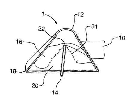
In the embodiments of the Device (1) illustrated in the Figures, the Device is
made of
plastic, resembling a cone with a fluid inlet (10) and discharge (12), a gas
inlet (14)
and an interior feature, helically cut conical member (also referred to as the
Unicorn)
(16), which assists in maximum pressure and velocity gradients to ensure peak
efficiency of gas infusion. Other suitable materials may be used for
construction.
The device is made such that under normal operation it may be submerged in the
fluid
body it discharges to.
The device main shape is a frustum, with the smallest end acting as the
discharge end,
defining an outlet port. The axis of rotation is defined by the line drawn
through the
center of both parallel ends of the frustum. Figure 4 shows a preferred ratio
of frustum
large diameter, small diameter and inlet, outlet size ratios for ideal
injection of gas. It
should be understood that variations in these ratios are contemplated by the
herein
invention.
3
CA 02715804 2010-08-17
WO 2009/103158
PCT/CA2009/000198
The discharge orifice can be equal in size to the inlet pipe or it can be of
another
dimension. An example embodiment includes a discharge orifice that is 25%
smaller
than the inlet diameter.
The inlet pipe can be of any size, but an example embodiment is 35% of the
large end
base (17) diameter (18) of the frustum. Under different inlet and outlet
conditions the
unit will continue to function, but efficiency will be compromised.
In an example embodiments shown, the inlet pipe is within 3 degrees of
tangential to
the inner curvature of the surface (31) of the frustum. The inlet pipe is
parallel to the
large diameter end of the frustrum. In the example embodiments, the inlet pipe
enters
the Device near the large end of the frustum.
While the inlet pipe must allow fluid into the main cavity, preferably it
should not
extend into the main cavity. Any objects other than The Unicorn in the cavity
may
disrupt uniform fluid flow and may lower the performance of the unit.
The main cavity of The Device serves the function of accepting the pressurized
fluid
such as water at its inlet and creating a rotating body of fluid about the
axis of rotation
that is constantly being replenished at the same rate that it discharges
through the
discharge orifice.
The large diameter end of The Device has an inclined ramp starting (zero
elevation
with respect to the large diameter end) in line with the fluid inlet. This
ramp follows
and fills the space between the inner surface of the frustum and the outer
surface of
The Unicorn. The ramp continues around until it terminates at the same point
where it
started (one rotation of the cavity). In the example embodiments, the total
elevation of
the ramp is 1140th of the height of The Device. Depending on configuration,
other
ramp tapers may be used to lesser or more effect. The ramp serves the purpose
of
added acceleration and swirling motion of the fluid.
The main cavity of the device is tapered such that the rotating fluid is
constantly
pushed towards the discharge as new fluid is received by the device. The taper
of the
4
CA 02715804 2010-08-17
WO 2009/103158
PCT/CA2009/000198
frustum increases the velocity of the rotating fluid as it has less space to
occupy the
same volume of fluid.
Inside the main cavity there is a helically cut conical member ("The Unicorn"
(16))
whose base (17) is directly affixed to the Devices large diameter end, co-
axial with
the axis of rotation. The Unicorn helps accelerate the fluid rotation and
limits inner
cavity turbulence which can reduce the low pressure vortex in the center of
the cavity.
The Unicorn has a hollow center (20) running axially from large diameter base
to the
tip for the purpose of gas injection directly into the lowest pressure area
inside of the
cavity. The center of the Unicorn will have a opening (22) drilled
therethrough to
allow inlet of gas to the center of the swirling mass.
The gas will enter the Unicorn from a small hole, pipe or other feature (14)
in the
large diameter end of the frustum that is connected in a sealed manner to the
large
diameter end of the Unicorn. The gas will exit the Unicorn from the tip or
small
diameter end (22) of the Unicorn.
The gas supply can be connected either from a pressurized source or from one
at
atmospheric pressure. If the gas is connected to a pressurized source, the
supply may
need to be regulated to ensure optimal operation of the Device. If the gas is
at
atmospheric pressure, there has to be sufficient fluid supply to the device to
create the
low pressure vortex in the axial center of the Device to draw the gas to
whatever
depth the unit is running at. Typically, the device when fed with fluid at 20
psi will
create 5 psi of vacuum. For every 1 psi, the unit will draw gas through 2.31
ft of fluid.
The device of the herein invention uses a swirling mass of fluid to generate a
low
pressure area in the center of said swirling liquid to draw in gas, breaking
gas into a
multitude of very fine bubbles, so the increased surface area of said bubbles
has a
maximum potential and ability to diffuse their contained gas to the
surrounding fluid
they are submerged in.
It should be understood that many changes, modifications, variations and other
uses
and applications will become apparent to those skilled in the art after
considering the
specification and the accompanying drawings. Therefore, any and all such
changes,
5
CA 02715804 2010-08-17
WO 2009/103158
PCT/CA2009/000198
modifications, variations and other uses and applications which do not depart
from the
spirit and the scope of the invention are deemed to be covered by the
invention.
6