Note: Descriptions are shown in the official language in which they were submitted.
CA 02715837 2010-08-18
DUAL SCREEN DISPLAY SYSTEM
BACKGROUND
[0001] The application generally relates to a dual screen display system. The
application
relates more specifically to a dual screen display system having a hinging
system that permits
the dual screens to be arranged in multiple positions.
[0002] Many dual screen display systems use a center hinge arrangement between
the
two screens. The center hinge arrangement locks the two screens together and
limits the
positions of the two screens relative to one another. The use of the center
hinge permits the
screens to be moved between a first position where the screens are stacked on
top of one
another and a second position where the screens are positioned side-by-side,
similar to the
movements associated with opening and closing a book. One drawback to the use
of the
center hinge is that it prevents the screens from being arranged in a position
where one screen
can be positioned to show information to one or more people such as during a
presentation
while the other screen can still be utilized by the user of the system giving
the presentation.
[0003] Therefore what is needed is a hinging system for a dual screen display
system
that permits the two screens in the dual screen display system to be quickly
and easily
positioned into a variety of different positions, including positions that
require the one screen
to be rotated independent of the other screen.
SUMMARY
[0004] The present application relates to a display system including a first
display device
having a first screen and a second display device having a second screen. The
display system
also includes a hinging system connecting the first display device and the
second display
device. The hinging system includes a first member connected to the first
display device and
a second member having a first end and a second end opposite the first end.
The first
member is configured to rotate relative to the first display device. The
second member is
connected to the first member at the first end and the second member is
connected to the
second display device at the second end. The second member is configured to
rotate relative
to the first member. The second display device is configured to rotate
relative to the second
-1-
CA 02715837 2010-08-18
member. The hinging system is configured and positioned to permit the second
display
device to rotate independently of the first display device.
[0005] The present application further relates to a system to connect a first
display device
to a second display device including a first member connectable to a first
display device with
a first connector and a second member connected to the first member with a
second
connector. The first connector is configured and positioned to permit the
first member to
rotate relative to the first display device. The second connector is
configured and positioned
to permit the second member to rotate relative to the first member. The second
member is
connectable to a second display device with a third connector. The third
connector is
configured and positioned to permit the second display device to rotate
relative to the second
member. The first member, the second member, the first connector, the second
connector
and the third connector are configured to permit the second display device to
be positioned at
a distance from the first display device.
BRIEF DESCRIPTION OF THE FIGURES
[0006] FIG. 1 shows a perspective view of an exemplary embodiment of a dual
screen
system in a closed position.
[0007] FIG. 2 shows a perspective view of an exemplary embodiment of a dual
screen
system in an open position.
[0008] FIGS. 3 and 4 show opposing perspective views of an exemplary
embodiment of a
dual screen system in an another open position.
[0009] FIG. 5 shows a perspective view of an exemplary embodiment of a dual
screen
system in a further open position.
[0010] FIG. 6 shows a perspective view of an exemplary embodiment of a dual
screen
system in still another open position.
[0011] FIG. 7 shows a side view of an exemplary embodiment of the dual screen
system.
[0012] FIG. 8 shows a side view of an exemplary embodiment of the dual screen
system
moving between three separate positions.
-2-
CA 02715837 2010-08-18
[0013] FIGS. 9 and 10 show side views of an exemplary embodiment of the dual
screen
system being moved between open positions.
DETAILED DESCRIPTION OF THE EXEMPLARY EMBODIMENTS
[0014] FIGS. 1-6 show one embodiment of a display system in different
positions.
Display system 100 can include a first display device 102 connected to a
second display
device 104 by a hinge system 106. Each of the first display device 102 and the
second
display 104 includes a screen 108. The screen 108 is the portion of the
surface area of the
corresponding display device on which light patterns, such as characters,
shapes, images,
lines, etc., are formed for viewing by a user. In one exemplary embodiment,
the screens 108
of the display devices 102, 104 can be substantially equal in size. However,
in other
exemplary embodiments, the screens 108 of the display devices 102, 104 can be
of different
sizes.
[0015] In an exemplary embodiment, one or both of the first display device 102
and the
second display device 104 can be operated as a display or monitor that is used
to display, on
screen 108, a corresponding video signal(s) that may be provided to the
display device. The
display devices 102, 104 can be any suitable type of flat panel display, e.g.,
a liquid crystal
display (LCD) or a gas plasma display. Further, the display devices 102, 104
may include a
LCD that uses technology such as cold cathode fluorescent lamp (CCFL) and/or
light
emitting diode (LED) for backlighting.
[0016] In an exemplary embodiment, the first display device 102 and the second
display
device 104 can display a common video signal that is provided to one or both
of the display
devices 102, 104. The common video signal can be provided, using either a
wired or wireless
connection, to both display devices 102, 104 at the same time or one of the
display devices
102, 104 can receive the video signal and then transmit, using either a wired
or wireless
connection, an appropriate video signal(s) to the other display device. In
another exemplary
embodiment, each of the first display device and the second display device can
receive and
display different or independent video signals. The video signal(s) displayed
by display
devices 102, 104 can be provided from any suitable video source and can
include a computer,
a computer network, e.g., a local area network, an intranet or the Internet, a
video playback
device, e.g., a DVD player or video camera, or a direct video source, e.g., a
cable or satellite
TV connection. The display devices 102, 104 can include corresponding
connections (both
-3-
CA 02715837 2010-08-18
wired and wireless) in order to receive video signals. Additionally, the
display devices 102,
104 may include internal switching devices, logic or functionality to adjust
the image on
screens 108 for correct viewing between the landscape position and the
portrait position
based on the orientation of the display devices 102, 104. The internal
switching devices,
logic or functionality can also invert the image on one or both of screens 108
of the display
devices 102, 104 for correct viewing by a user.
[0017] In an exemplary embodiment, one or both of the first display device 102
and the
second display device 104 can include one or more suitable types of computing
devices, e.g.,
central processing units (CPUs) or microprocessors, an internal power supply
and one or
more suitable types of memory devices, e.g., random access memory (RAM), read
only
memory (ROM), flash memory, or internal hard drive. In another exemplary
embodiment,
the computing devices and memory devices may receive information and data from
sources
such as flash memory devices, CDs, DVDs, or mini DVDs. The computing devices
can
execute algorithms or computer programs that are stored in the memory devices
to provide
the display device with additional processing capabilities in addition to
displaying video
signals. The inclusion of computing devices and memory devices in a display
device can
enable the display device to generate video signals that can be displayed by
the display
device itself and/or displayed by the other display device.
[0018] In addition, the display devices 102, 104 can include one or more
connections
(both wired and wireless) to receive input from other external sources or
devices. For
example, the display devices 102, 104 can include modem, Ethernet or Firewire
ports or
connection points to receive and/or transmit information and data over wired
connections. In
addition, the display devices 102, 104 may also include an antennae and/or
transceiver to
receive and/or transmit information and data over wireless connections.
Further, the display
devices 102, 104 can include any suitable type of audio, video or data
connection point or
port such as microphone ports, audio input ports, external headphone ports,
speaker ports,
and universal serial bus (USB) ports.
[0019] In a further exemplary embodiment, screen 108 of one or both of the
display
devices 102, 104 can include any suitable touch screen overlay or technology,
such as
resistive, electromagnetic, or multitouch technologies. The touch screen
overlay can be used
to provide input capabilities to the display device and can be used by the
user to enter and
execute commands to be executed by the computing device(s).
-4-
CA 02715837 2010-08-18
[0020] In another exemplary embodiment, one or both of the display devices
102, 104
can include port(s) or connection points for electricity and power to be
provided to the
display device. One or both display devices 102, 104 may have electrical
storage
capabilities, such as a battery, power cell or capacitor, to store received
power or electricity
for use at a later time by the display device. The display devices 102, 104
may include one or
more external contacts, points, or pads to enable the transfer of electricity
and power from
one display device to the other display device.
[0021] FIG. 1 shows the display system 100 in a closed position. In the closed
position,
screen 108 of display device 102 faces screen 108 of display device 104. The
positioning of
screens 108 in a facing position can protect the screens 108 from exterior
forces that may
damage the screens 108. In an exemplary embodiment, one or both of display
devices 102,
104 may include a power switch that can automatically turn off one or both of
the display
devices 102, 104 when the display system 100 is moved into the closed
position.
[0022] FIG. 2 shows the display system 100 in an open position with both
screens 108 of
corresponding display devices being positioned or located substantially in the
same plane.
The open position of the display system 100 shown in FIG. 2 permits the
display system 100
to be placed substantially flat on a surface, either vertically or
horizontally, with both screens
108 being viewable by a user.
[0023] In an exemplary embodiment, display device 102 and/or display device
104 may
be configured to use a Video Electronics Standards Association (VESA) mounting
system to
mount the display system 100 in a vertical (or horizontal) orientation. One or
both displays
devices 102, 104 can include a 75 mm or 100 mm hole pattern, which holes may
be
configured to receive a threaded connector, on the side of the display
device(s) opposite the
screen 108. The hole pattern is configured and positioned to receive
components of a
mounting bracket that conforms to the VESA standard. In another exemplary
embodiment,
display device 102 and/or display device 104 may include a leg (or multiple
legs) that can
extend from the side of the display device opposite the screen 108 to provide
support for a
vertically positioned display system 100.
[0024] FIGS. 3 and 4 shows the display system 100 in an open position with
display
device 104 being oriented substantially perpendicular to display device 102.
The open
position of the display system 100 shown in FIGS. 3 and 4 permits users
located on one side
-5-
CA 02715837 2010-08-18
of the display system 100 to view both screens 108 and prevents users on the
other side of the
display system 100 from being able to view either screen 108. In an additional
exemplary
embodiment, display device 104 can be oriented at an acute angle, i.e., an
angle less than 90
degrees, to display device 102. In another exemplary embodiment, display
device 104 can be
oriented at an obtuse angle, i.e., an angle greater than 90 degrees, to
display device 102.
[00251 FIG. 5 shows the display system 100 in an open position with screen 108
from
display device 104 being positioned above the screen 108 from display device
102. In the
open position from FIG. 5, screen 108 from display device 102 is substantially
blocked from
view by display device 104, thereby rendering screen 108 from display device
102 a non-
viewable screen. The open position of display system 100 in FIG. 5 provides a
compact
footprint while still enabling one of the screens 108 to be viewable (and
usable) to a user.
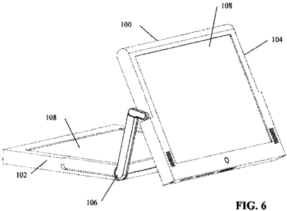
[00261 FIG. 6 shows the display system 100 in an open position with display
device 104
being positioned separate from display device 102. Screen 108 from display
device 104 can
be oriented to permit users on the opposite side of display system 100 to
display device 102
to be able to view screen 108 of display device 104. In other words, when
display device 104
is positioned between a user and display device 102, the user can view screen
108 of display
device 104. However, in this position, the users viewing screen 108 of display
device 104
would not be able to view screen 108 of display device 102. Similarly, users
who are able to
view screen 108 of display device 102 would not be able to view screen 108 of
display device
104. In other words, when display device 102 is positioned between a user and
display
device 104, the user can view screen 108 of display device 102, but not screen
108 of display
device 104.
[00271 FIG. 7 shows the hinge system 106 of display system 100. As shown in
FIG. 7,
the display system 100 includes a base unit 202, which corresponds to first
display unit 102
of FIGS. 1-6, and a rotatable unit 204, which corresponds to second display
unit 104 of FIGS.
1-6. The rotatable unit 204 is connected to the base unit 202 by hinge system
106 that
includes a pair of hinges positioned on the sides of each unit. In another
exemplary
embodiment, hinge system 106 may include only one hinge positioned on one side
of the
display system 100.
[00281 Each hinge has a first arm 206 that is rotatably connected to the base
unit 202 by
a second arm 208 that is rotatably connected to the rotatable unit 204. The
first arm 206 and
-6-
CA 02715837 2010-08-18
the second arm 208 are rotatably connected to each other. The first arm 206
can rotate at an
angle a relative to the base unit 202. In an exemplary embodiment, the angle a
can range
from about 0 degrees to about 180 degrees. However, in other exemplary
embodiments, the
angle a can range from 0 degrees to substantially more or less than 180
degrees. The first
arm 206 can be connected to the base unit 202 by any suitable connector,
connection
technique or connection mechanism that permits rotation of the first arm 206
and can hold or
maintain the position of the first arm 206 relative the base unit 202 without
the application of
any external forces. The positioning of the first arm 206 relative to the base
unit 202 can be
continuously adjustable along the range of motion of the first arm 206 or the
positioning of
the first arm 206 relative to the base unit 202 can involve a series of
predetermined
intermediate positions, e.g., the first arm 206 can be positioned at 5 or 10
degree increments
with respect to the base unit 202.
[0029] The second arm 208 can rotate at an angle R relative to the first arm
206. In an
exemplary embodiment, the angle R can range from about 0 degrees to about 90
degrees.
However, in other exemplary embodiments, the angle [i can range from 0 degrees
to
substantially more or less than 90 degrees. In another exemplary embodiment,
the angle 0
can range up to about 100 degrees. The second arm 208 can be connected to the
first arm 206
by any suitable connector, connection technique or connection mechanism that
permits
rotation of the second arm 208 and can hold or maintain the position of the
second arm 208
relative the first arm 206 without the application of any external forces. The
positioning of
the second arm 208 relative to the first arm 206 can be at the ends of the
range of motion of
the second arm 208 relative to the first arm 206, e.g., the second arm 208 can
be positioned
only at 0 degrees and 90 degrees, continuously adjustable along the range of
motion of the
second arm 208, or at a series of predetermined intermediate positions, e.g.,
the second arm
208 can be positioned at 5 or 10 degree increments with respect to the first
arm 206. In a
further exemplary embodiment, a spring may be connected internally between the
second arm
208 and the first arm 206 to provide additional tensioning between the second
arm 208 and
the first arm 206 in order to better maintain the relative positioning of the
second arm 208
and the first arm 206.
[0030] The rotatable unit 204 can rotate at an angle y relative to the second
arm 208. In
an exemplary embodiment, the angle y can range from about 0 degrees to about
180 degrees.
However, in other exemplary embodiments, the angle y can range from 0 degrees
to
-7-
CA 02715837 2010-08-18
substantially more or less than 180 degrees. In another exemplary embodiment,
the angle y
can range up to about 270 degrees. The rotatable unit 204 can be connected to
the second
arm 208 by any suitable connector, connection technique or connection
mechanism that
permits rotation of the rotatable unit 204 and can hold or maintain the
position of the
rotatable unit 204 relative the second arm 208 without the application of any
external forces.
The positioning of the rotatable unit 204 relative to the second arm 208 can
be continuously
adjustable along the range of motion of the rotatable unit 204 or the
positioning of the
rotatable unit 204 relative to the second arm 208 can involve a series of
predetermined
intermediate positions, e.g., the rotatable unit 204 can be positioned at 5 or
10 degree
increments with respect to the second arm 208. The movement of the first arm
206 along
angle a, the movement of the second arm 208 along angle 0, and the movement of
the
rotatable unit 204 about angle y, permit the display devices 102, 104 of
display device 100 to
be moved into a desired position for use by the user. In an exemplary
embodiment, the axes
of rotation of associated with angles a, R, and y are substantially parallel.
[00311 In an exemplary embodiment, the first arm 206 can be longer than the
second arm
208. However, in other exemplary embodiments the first arm 206 and the second
arm 208
can be the same length or the second arm 208 can be longer than the first arm
206. Any
changes or adjustments to the lengths of the first arm 206 and the second arm
208 would
result in corresponding changes in the connection points to the units and the
possible ranges
of motion of the first arm 206 and the second arm 208. In still another
embodiment, one or
more additional arms may be rotatably connected between the first arm 206 and
the second
arm 208. These additional arms can provide additional positioning options for
the base unit
202 and the rotatable unit 204.
[00321 FIG. 8 shows the movement of the hinge system 106 of the display system
100
from the closed position to an open position. The base unit 202 and the
rotatable unit 204
start in the closed position (see e.g., FIG. 1). In the closed position, the
second arm 208 is
substantially perpendicular to the first arm 206. The rotatable unit 204 can
then be moved to
a first open position substantially perpendicular to the base unit 202 (see
e.g., FIGS. 3 and 4).
When the rotatable unit 204 is moved into the first open position, the first
arm 206 is rotated
about 90 degrees, while the second arm 208 is maintained in the same position,
i.e., the
second arm 208 is not rotated. Finally, the rotatable unit 204 is moved to a
second open
position substantially parallel to the base unit 202 (see e.g., FIG. 2). When
the rotatable unit
-8-
CA 02715837 2010-08-18
204 is moved into the second open position, the first arm 206 is rotated about
another 90
degrees (about 180 degrees total) and the second arm 208 is rotated about 90
degrees to be
substantially coaxial or in alignment with the first arm 206.
[00331 FIGS. 9 and 10 show the movement of the hinge system 106 of the display
system
100 between different open positions. The rotatable unit 204 starts in an open
position AA
relative to the base unit 202 and the first arm 206 and the second arm 208 are
substantially
coaxial or in alignment. In open position AA, the screen 108 of the rotatable
unit 204 is
facing the screen 108 of the base unit 202. The rotatable unit 202 can then be
rotated about
180 degrees about the second arm 208 into an open position BB. In open
position BB, the
screen 108 of the rotatable unit 204 is not facing the screen 108 of the base
unit 202, i.e.,
screen 108 of the rotatable unit 204 is opposite the screen 108 of the base
unit 202. As shown
in FIG. 9, the second arm 208 can be moved to be at an angle less than 90
degrees with
respect to first arm 206 for open position BB. However, as shown in FIG. 10,
the first arm
206 and the second arm 208 can maintain the same position relative to one
another for
position BB of the rotatable unit 202. Finally, from position BB, the second
arm 208 can be
rotated about 90 degrees relative to the first arm 206 to move rotatable unit
204 into open
position CC (see e.g., FIG. 6). When the rotatable unit 204 is moved into
position CC, the
first arm 206 maintains its position and only the second arm 208 is rotated.
[00341 Another embodiment is directed to an articulated hinge system for
electronic
housings/video screens or assemblies. The articulated hinge system uses two
two-part
hollow articulated hinge arms which allow for electronic wire transfer between
the two video
screen assemblies. The hinge system can be positioned on two parallel sides of
two video
screen assemblies which may or may not have additional electronic components
in
combination with those video screens. The hinge system allows the video screen
assemblies
to be moved to various positions individually unique to each other. The hinge
system is
made up of a longer arm attached to one video screen assembly allowing for
resistive 180
degree rotation. Attached to the longer arm is a smaller arm whose position
can "rest" in one
of two positions thereby having 90 degree movement to the longer arm. On the
end of this
smaller arm is attached the second video screen assembly which has resistive
rotation of 180
degrees.
[00351 One embodiment relates to a combined system, including an arm system
and
display devices, that permits a user to manipulate the display devices
uniquely and
-9-
CA 02715837 2010-08-18
independently of one another to enable the combined system to be configured in
multiple
positions for "on demand" user applications.
[00361 Another embodiment relates to a combined system, including an arm
system and
display devices, that permits usage of the display devices and then the return
of the display
devices to a closed position for storage and transport, thereby protecting the
display devices.
[00371 A further embodiment relates to a combined system, including an arm
system and
display devices, wherein the arm system is configured to permit wires to
travel through the
arm system, thereby enabling data, power, information and/or electricity to be
transferred
between the display devices.
[00381 Still another embodiment is related to a combined system, including an
arm
system and display devices, wherein the display devices can be connected to an
information
source (e.g., a computer, the Internet or other computer network, such as an
intranet), by wire
or wirelessly, to receive information that can be displayed either uniquely or
severally, i.e.,
individually on one screen or jointly on both screens, as the user or sender
may dictate.
[00391 Yet another embodiment is related to an arm system having an arm design
that can
permit adjustments to measurements A-B, and B-C (see FIG. 8) to accommodate
different
sizes and thicknesses of display devices.
[00401 An additional embodiment is related to display devices that can have an
integrated
power switch to turn off the display devices when the display devices are
returned to the
closed position.
[00411 Another embodiment is related to a combined system, including an arm
system
and display devices, that can permit the display devices to be positioned at
180 degrees
relative to one another and to be oriented in a landscape or portrait position
in a wall or
tabletop mode with the use of a Video Electronics Standards Association
mounting system.
The connection to the mounting system can be achieved by providing a 75 mm or
100 mm
hole pattern, which may include threaded holes, on the rear of one or both of
the display
devices.
[00421 A further embodiment is related to a combined system, including an arm
system
and display devices, wherein the display devices may have internal switching
devices, logic
-10-
CA 02715837 2010-08-18
or functionality to adjust the image on the screens for correct viewing
between the landscape
position and the portrait position.
[00431 Yet another embodiment relates to a combined system, including an arm
system
and display devices, that can provide for information transfer by wire or
wirelessly to one or
both display devices, severally or jointly, to permit the unique usage of
information
transferred to each display device, and that can enable information to be
displayed uniquely
on each screen as dictated by the user or source application.
[00441 Still another embodiment relates to display devices that can be
positioned as
shown in FIG. 6 to enable multiple users, or groups of users, to view distinct
information in
private with respect to the other user or group of users.
[00451 An additional embodiment relates to more than one combined system, each
including an arm system and display devices, that can be connected either by
wire or
wirelessly to one another, or that can be connected by wire or wirelessly to a
shared or
common data or information source to display information collectively, i.e.,
all screens
display the same information, individually, i.e., each screen displays
information unique to
that screen, or some combination of collectively and individually, i.e., one
or more screens
display the same information and one or more screens display information
unique to that
screen.
[00461 Another embodiment relates to a combined system, including an arm
system and
display devices, wherein one or both display devices may include one or more
of: central
processing units (CPUs) or microprocessors; internal power supplies; or memory
devices that
can store information received from external sources such as flash memory
devices, CDs,
DVDs, mini DVDs, or from transmissions over wired connections, e.g., Ethernet
or Firewire,
or wireless connections.
[00471 A further embodiment relates to a combined system, including an arm
system and
display devices, wherein one or both display devices may include internal
memory devices
such as random access memory (RAM) and/or read only memory (ROM).
[00481 Still another embodiment relates to a combined system, including an arm
system
and display devices, wherein one or both display devices may include an
internal hard drive
(memory device).
-11-
CA 02715837 2010-08-18
[00491 Yet another embodiment relates to a combined system, including an arm
system
and display devices, wherein one or both display devices may include liquid
crystal display
(LCD) screens and/or plasma screens.
[00501 An additional embodiment relates to a combined system, including an arm
system
and display devices, wherein one or both display devices may include LCD
screens that
utilize backlighting technology such as cold cathode fluorescent lamp (CCFL)
and/or light
emitting diode (LED).
[00511 Another embodiment relates to a combined system, including an arm
system and
display devices, wherein one or both display devices may include touch screen
overlays on
one or both screens. The overlay treatments used on the screen(s) may utilize
resistive,
electromagnetic, or multitouch technology.
[00521 A further embodiment relates to a combined system, including an arm
system and
display devices, wherein one or both display devices may include an Ethernet
port to enable
Ethernet connectivity.
[00531 Still another embodiment relates to a combined system, including an arm
system
and display devices, wherein one or both display devices may include a Modem
port to
permit connectivity by way of a modem.
[00541 Yet another embodiment relates to a combined system, including an arm
system
and display devices, wherein one or both display devices may include an
antennae or
transceiver to enable wireless connectivity.
[00551 Another embodiment relates to a combined system, including an arm
system and
display devices, wherein one or both display devices may include Firewire
ports.
[00561 A further embodiment relates to a combined system, including an arm
system and
display devices, wherein one or both display devices may include microphone
ports.
[00571 Still another embodiment relates to a combined system, including an arm
system
and display devices, wherein one or both display devices may include audio
input ports.
-12-
CA 02715837 2010-08-18
[0058] Yet another embodiment relates to a combined system, including an arm
system
and display devices, wherein one or both display devices may include external
headphone
ports.
[0059] An additional embodiment relates to a combined system, including an arm
system
and display devices, wherein one or both display devices may include speaker
ports.
[0060] A further embodiment relates to a combined system, including an arm
system and
display devices, wherein one or both display device may include one or more
universal serial
bus (USB) ports.
[0061] Still another embodiment relates to a combined system, including an arm
system
and display devices, wherein one or both display devices may include port(s)
or connection
points to receive an electrical connection to provide electricity to the
display device.
[0062] Yet another embodiment relates to a combined system, including an arm
system
and display devices, wherein one or both display devices may have electrical
storage
capability such as a battery, power cell or capacitor.
[0063] An additional embodiment relates to a combined system, including an arm
system
and display devices, wherein one or both display devices may have one or more
external
contacts, points, or pads to enable the transfer of electricity from one
display device to the
other.
[0064] While only certain features and embodiments of the invention have been
shown
and described, many modifications and changes may occur to those skilled in
the art (e.g.,
variations in sizes, dimensions, structures, shapes and proportions of the
various elements,
values of parameters (e.g., temperatures, pressures, etc.), mounting
arrangements, use of
materials, colors, orientations, etc.) without materially departing from the
novel teachings and
advantages of the subject matter recited in the claims. For example, elements
shown as
integrally formed may be constructed of multiple parts or elements, the
position of elements
may be reversed or otherwise varied, and the nature or number of discrete
elements or
positions may be altered or varied. The order or sequence of any process or
method steps
may be varied or re-sequenced according to alternative embodiments. Also, two
or more
steps may be performed concurrently or with partial concurrence. It is,
therefore, to be
understood that the appended claims are intended to cover all such
modifications and changes
-13-
CA 02715837 2010-08-18
as fall within the true spirit of the invention. Furthermore, in an effort to
provide a concise
description of the exemplary embodiments, all features of an actual
implementation may not
have been described (i.e., those unrelated to the presently contemplated best
mode of carrying
out the invention, or those unrelated to enabling the claimed invention). It
should be
appreciated that in the development of any such actual implementation, as in
any engineering
or design project, numerous implementation specific decisions may be made.
Such a
development effort might be complex and time consuming, but would nevertheless
be a
routine undertaking of design, fabrication, and manufacture for those of
ordinary skill having
the benefit of this disclosure, without undue experimentation.
-14-