Note: Descriptions are shown in the official language in which they were submitted.
CA 02716060 2010-09-30
SEAL ANCHOR WITH NON-PARALLEL LUMENS
[0001]
BACKGROUND
1. Technical Field
[00021 The present disclosure relates to a seal for use in a
surgical procedure. More
particularly, the present disclosure relates to a seal anchor member adapted
for insertion into an
incision in tissue and including a plurality of non-parallel lumens adapted
for the sealed
reception of one or more surgical objects such that a substantially fluid-
tight seal is formed with
both the tissue and the surgical object or objects.
2. Background of the Related Art
[0003] Today, many surgical procedures are performed through
small incisions in the
skin, as compared to the larger incisions typically required in traditional
procedures, in an effort
to reduce both trauma to the patient and recovery time. Generally, such
procedures are referred
to as "endoscopic", unless performed on the patient's abdomen, in which case
the procedure is
referred to as "laparoscopic". Throughout the present disclosure, the term
"minimally invasive"
should be understood to encompass both endoscopic and laparoscopic procedures.
[0004] During a typical minimally invasive procedure, surgical
objects, such as surgical
=
access devices (e.g., trocar and cannula assemblies) or endoscopes, are
inserted into the patient's
body through an incision in tissue. In general, prior to the introduction of
the surgical object or
1
CA 02716060 2010-09-30
instrument into the patient's body, insufflation gasses are used to enlarge
the area surrounding
the target surgical site to create a larger, more accessible work area.
Accordingly, the
maintenance of a substantially fluid-tight seal is desirable so as to prevent
the escape of the
insufflation gases and the deflation or collapse of the enlarged surgical
site.
100051 To this end, various valves and seals are used during the course of
minimally
invasive procedures and are widely known in the art. Various seals have been
developed
including lumens for the reception of surgical instruments. Depending upon the
needs of a
particular surgical procedure, instruments may need to be angled with respect
to one another for
extended periods of time. Holding the instruments at angles with respect to
one another and/or
overcoming the internal biases of the seal anchor member through which the
instruments are
inserted may fatigue the surgeon and/or breach the fluid-tight barrier between
the seal anchor
member and surrounding tissue.
[0006] Accordingly, a continuing need exists for new seal anchor members
that can be
inserted directly into the incision in tissue and that can accommodate a
variety of surgical objects
or instruments while maintaining the integrity of an insufflated workspace.
SUMMARY
[0007] Disclosed herein is a seal anchor member including a housing
including leading
and trailing ends, and one or more lumens extending therethrough. Each of the
lumens is
adapted for receiving a surgical instrument in a substantially sealed
reception. The one or more
lumens are angled with respect to a longitudinal axis of the housing. At least
two of the lumens
define axes that are non-parallel with respect to one another. In an
embodiment, the housing
may include a plurality of lumens, e.g., three lumens, in which one of the
lumens is parallel with
respect to the longitudinal axis and the other two lumens are non-parallel
with respect to each
2
CA 02716060 2010-09-30
other and the longitudinal axis. As described herein, the lumens, while
defining axes that are
intersecting, do not cross each other since the lumens are laterally spaced
apart, e.g., the axes, not
the lumens, are intersecting when the housing is viewed in a side cross-
sectional view. This
arrangement of the lumens facilitates the simultaneous, non-parallel placement
of multiple
surgical objects or instruments within the seal anchor member. However, in
other embodiments,
the lumens may be intersecting.
[0008] Furthermore, the lumens may define openings at the leading end that
are radially
spaced apart about the trailing end. Alternatively, the lumens may define
openings at the leading
end that are spaced along a diameter of the trailing end. The openings defined
by the lumens
may be staggered about an axis of the trailing end or may be positioned along
a diameter but
offset from that diameter. Alternatively, the openings defined by the lumens
may be positioned
on a chord or a diameter of the trailing end.
[0009] The housing may be formed from a compressible material to
facilitate adjusting
the angles between instruments inserted within the lumens and with respect to
the longitudinal
axis of the housing. In the absence of a force, e.g, a radial force, upon the
instruments inserted
within the lumens, the lumens are angled, i.e., non-parallel, with respect to
each other. During
use, the angles of the lumens are adjustable by applying a force.
[00101 The leading end may include a groove, cut-out, or recess that is
positioned
adjacent to the proximal end of at least one of the lumens. The groove is
configured and adapted
to facilitate the insertion of the instrument into the lumen by stabilizing
the instrument and
leading the instrument into the lumen. The groove may be generally arcuate.
The groove may
narrow from the proximal end to the distal end of the groove. The groove may
extend radially
outward from the proximal end of the at least one lumen.
3
CA 02716060 2010-09-30
[0011] Furthermore, the housing of the seal anchor may be adapted to
transition between
a first compressed condition to facilitate at least partial insertion of the
seal anchor member
within a tissue tract, and a second expanded condition to facilitate securing
of the seal anchor
member within the tissue tract and in substantial sealed relation with tissue
surfaces defining the
tissue tract. In an embodiment, the housing may be formed from a compressible
material or from
a foam material. In an embodiment, the foam material may be at least partially
constituted of a
material selected from the group consisting of polyisoprene, urethane, and
silicone. In another
embodiment, the housing may be formed from a gel material.
[0012] The housing may also define a substantially arcuate configuration.
The housing
may define a substantially hour glass shape. Furthermore, the lumens may
define openings at the
leading end that are radially spaced apart about the trailing end.
Alternatively, the lumens may
define openings at the leading end that are spaced along a diameter of the
trailing end. The
openings defined by the lumens may be staggered about an axis of the trailing
end or may be
positioned along a diameter but offset from that diameter. Alternatively, the
openings defined by
the lumens may be positioned on a chord or a diameter of the trailing end.
[0013] These and other features of the apparatus disclosed herein will
become more
readily apparent to those skilled in the art from the following detailed
description of various
embodiments of the present disclosure.
BRIEF DESCRIPTION OF THE DRAWINGS
[0014] Various embodiments of the present disclosure are described
hereinbelow with
references to the drawings, wherein:
[0015] Fig. 1 is a front perspective view of a seal anchor in accordance
with the present
disclosure shown relative to tissue;
4
CA 02716060 2016-12-02
[0016] Fig. 2A is a front perspective view of a seal anchor member having
lumens
therein that are parallel to one another;
[0017] Fig. 2B is a front perspective view of the seal anchor of Fig. 1
shown with
medical instruments inserted therein;
[0018] Fig. 3 is another embodiment of a seal anchor in accordance with the
present
disclosure; and
[0019] Fig. 4 is a yet another embodiment of a seal anchor in accordance
with the present
disclosure,
DETAILED DESCRIPTION OF THE EMBODIMENTS
[0020] In the drawings and in the description which follows, in which like
references
numerals identify similar or identical elements, the term "proximal" will
refer to the end of the
apparatus which is closest to the clinician during use, while the term
"distal" will refer to the end
which is furthest from the clinician, as is traditional and known in the art.
A seal anchor for use
in a surgical procedure is shown and described in U.S. Pat. Pub. 2009-0093752.
The seal anchor member may be used during a minimally invasive procedure in
which the
seal anchor is inserted into an incision. Alternatively, the seal anchor may
be used through a
naturally occurring opening (e.g., anus or vagina) or any incision in a
patient's skin.
[0021] The use and function of seal anchor member 100 will be discussed
during the
course of a typical minimally invasive procedure. Initially, the peritoneal
cavity (not shown) is
insufflated with a suitable biocompatible gas such as, e.g., CO2 gas, such
that the cavity wall is
raised and lifted away from the internal organs and tissue housed therein,
providing greater
access thereto. The insufflation may be performed with an insufflation needle
or similar device,
CA 02716060 2010-09-30
as is conventional in the an. Either prior or subsequent to insufflation, a
tissue tract 12 is created
in tissue "T", the dimensions of which may be varied dependent upon the nature
of the
procedure.
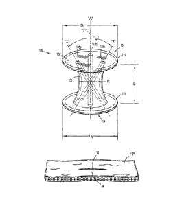
[0022] A seal anchor 100 will now be described with reference to Figs. 1
and 2. The seal
anchor 100 defines a longitudinal axis "A" and has respective trailing (or
proximal) and leading
(or distal) ends 102, 104 and an intermediate portion 106 disposed between the
trailing and
leading ends 102, 104. Seal anchor member 100 includes one or more lumens (or
ports) 108a,
108b, 108c disposed between the trailing and leading ends 102, 104 that define
corresponding
longitudinal axes "X", "Y", "Z". As seen in Fig. 1, the axes "X", "Y", "Z"
defined by the
lumens 108a, 108b, 108c, respectively, are non-parallel with respect to one
another. To facilitate
the simultaneous placement of instruments into each of the lumens 108a, 108b,
108c, the lumens
108a-c do not cross one another. The lumens 108a-c are laterally spaced apart
such that,
although the lumens 108a-c are angled with respect to one another, the lumens
108a-c do not
intersect one another. In other embodiments, however, lumens may be arranged
to cross one
another. In contrast to seal anchor 100, a seal anchor 90 having parallel, non-
intersecting lumens
98 is illustrated in Fig. 2A.
[0023] As seen in Fig. 2B, the lumens 108a-c are adapted to receive
instrumentation
therein in a substantially sealed manner. The lumens 108a-c are adapted to
inhibit the escape of
insufflation gasses within a body cavity with or without instrumentation being
inserted therein.
Accordingly, the lumens 108a-c have diameters that are adapted to contract in
the absence of a
surgical instrument inserted therein and are adapted to expand to accommodate
instrumentation
in a substantially sealed manner.
6
CA 02716060 2010-09-30
[0024] As shown in Fig. 2B, the instrumentation inserted within the lumens
108 may
include, but are not limited to, a camera 20 that may be inserted within one
of the lumens 108
and a pair of surgical instruments 21 that are inserted into two of the other
lumens 108. Since the
axes "X" and "Z" of the two lumens 108a, 108c, through which the pair of
surgical instruments
21 are inserted, cross one another, the distance between the distal ends of
the surgical
instruments 21 is greater than it would be if the axes "X", "Z" were parallel
to one another.
Since the lumens 108a, 108c define non-parallel axes, manipulation of the
surgical instruments
21 is facilitated since there is a lesser probability of the instruments 21
interfering with each
other's use. Furthermore, since the at-rest state for the lumens 108a-c is at
angles with respect to
one another, surgeon fatigue is reduced for those procedures necessitating
such positioning for an
extended duration of time. Adjustment of the angles of the lumens with respect
to one another is
facilitated by over.coming the internal biasing force of the seal anchor
member 100 by applying a
radial force to the surgical instrumentation placed within the lumens 108a-c.
(0025] As previously discussed, Fig. 2A illustrates a seal anchor 90
including lumens 98
that are parallel to one another. Inserted within lumens 98 are surgical
instruments 21 and
camera 20. As seen in Fig. 2A, the parallel configuration of the lumens 98
hinder camera 20 in
obtaining a clear view of the surgical site. It will be appreciated that the
non-parallel,
intersecting configuration of the lumens 108a-c of seal anchor 100 facilitate
obtaining a lesser
obstructed field of view than would be obtainable using seal anchor 90. In
particular, as shown
in Fig. 2B, axes "X" and "Z" define an angle "0" therebetween. The greater the
value of angle
"0", the lesser the probability of surgical instruments 21 obstructing the
view of camera 20.
Moreover, the greater the angle "A", the lesser the probability of
interference between
instruments 21 during the procedure. In addition, the greater the angle "0",
the greater the
7
CA 02716060 2010-09-30
number of internal structures included within the surgical field and within
reach of instruments
21.
[0026] Proximal end 102 of seal anchor member defines a first diameter Di
and distal end
104 defines a second diameter D2. In one embodiment of seal anchor member 100,
the
respective first and second diameters DI, D2 of the proximal and distal ends
102, 104 are
substantially equivalent, as seen in FIG. 1, although an embodiment of seal
anchor member 100
in which diameters DI, D2 are different is also within the scope of the
present disclosure. As
depicted in FIG. 1, proximal and distal ends 102, 104 define substantially
planar surfaces.
However, embodiments are also contemplated herein in which either or both of
proximal and
distal ends 102, 104, respectively, define surfaces that are substantially
arcuate to assist in the
insertion of seal anchor member 100 within a tissue tract 12 defined by tissue
surfaces 14 and
formed in tissue "T", e.g., an incision, as discussed in further detail below.
[00271 Intermediate portion 106 defines a radial dimension "R" and extends
longitudinally between proximal and distal ends 102, 104, respectively, to
define an axial
dimension or length "L". The radial dimension "R" of intermediate portion 106
varies along the
axial dimension, or length, "L" thereof. Accordingly, seal anchor member 100
defines a cross-
sectional dimension that varies along its length "L", which facilitates the
anchoring of seal
anchor member 100 within tissue "T", as discussed in further detail below.
However, an
embodiment of seal anchor member 100 in which the radial dimension "R" remains
substantially
uniform along the axial dimension "L" thereof is also within the scope of the
present disclosure.
[0028] The radial dimension "R" of intermediate portion 106 is appreciably
less than the
respective diameters DI, D2 of proximal and distal ends 102, 104 such that
seal anchor member
100 defines an "hour-glass" shape or configuration to assist in anchoring seal
anchor member
8
CA 02716060 2010-09-30
100 within tissue "T", as discussed in further detail below. However, in an
alternate
embodiment, the radial dimension "R" of intermediate portion 106 may be
substantially
equivalent to the respective diameters Di, D2 of proximal and distal ends 102,
104. In cross
section, intermediate portion 106 may exhibit any suitable configuration,
e.g., substantially
circular, oval or oblong.
[0029] The seal anchor 100 may be adapted to transition from an expanded
condition to a
compressed condition so as to facilitate the insertion and securement thereof
within tissue tract
12 in tissue "T". In the expanded condition, seal anchor 100 is at rest and
the respective radial
dimensions Di, D2 of the proximal and distal ends 102, 104 of seal anchor 100,
as well as the
radial dimension R of the intermediate portion 106 are such that the seal
anchor 100 cannot be
inserted within tissue tract 12. However, the seal anchor 100 may transition
to a compressed
condition such that proximal and distal ends 102, 104, as well as intermediate
portion 106 are
dimensioned for insertion into tissue tract 12.
[00301 To facilitate the transition between an expanded and a compressed
condition, the
seal anchor 100 may be formed from a compressible material having an internal
biasing force
such that the seal anchor 100 will transition back to an expanded condition
upon insertion of the
seal anchor 100 within tissue tract 12, thereby ensuring a seal between the
seal anchor 100 and
the tissue tract 12. Seal anchor 100 may be formed from a shape memory
material, a foam
material, or a gel material, or the like, but may also be formed from other
materials. In an
embodiment, the seal anchor 100 may be formed from a material selected from
the group
consisting of polyisoprene, urethane, and silicone.
[0031] Positioning members 114, 115 of the trailing and leading ends 102,
104,
respectively, may engage the walls defining the body cavity of the tissue
tract 12 to facilitate
9
CA 02716060 2010-09-30
securement of seal anchor member 100 within the body tissue. For example,
positioning
member 114 at leading end 104 may engage the internal peritoneal wall and
positioning member
114 adjacent trailing end 102 may engage the outer epidermal tissue adjacent
the incision 12
within tissue "T". In another embodiment of seal anchor member 100, one or
more additional
positioning members 114 may be associated with intermediate portion 106.
[0032] The use and function of seal anchor member 100 will be discussed
during the
course of a typical minimally invasive procedure. Initially, the peritoneal
cavity (not shown) is
insufflated with a suitable biocompatible gas such as, e.g., CO2 gas, such
that the cavity wall is
raised and lifted away from the internal organs and tissue housed therein,
providing greater
access thereto. The insufflation may be performed with an insufflation needle
or similar device,
as is conventional in the art. Either prior or subsequent to insufflation, a
tissue tract 12 is created
in tissue "T", the diMensions of which may be varied dependent upon the nature
of the
procedure.
[0033] Different embodiments of seal anchors will be described with
reference to Figs. 2
and 3. Seal anchors 200, 300 are substantially similar to seal anchor 100,
except in the
configuration of lumens and further include structures to stabilize
instrumentation inserted within
the lumens. Both seal anchor 200 and seal anchor 300, shown in Figs. 2 and 3,
include lumens
defining intersecting axes. Seal anchor 200 includes a trailing end 202 and a
distal end 204. A
plurality of lumens 208 is disposed between the trailing and leading ends 202,
204. Lumens 208
define openings in the trailing end 202 that are radially positioned along the
trailing end 202. A
cut-out or groove 201 in the leading end extending outward from at least one
lumen 208
facilitates stabilization of instrumentation inserted within the lumen 208.
CA 02716060 2010-09-30
[0034] In an alternative embodiment, a seal anchor 300 including plurality
of lumens
disposed between leading and trailing ends 302, 304 is shown in Fig. 4. A cut-
out or groove 301
in an arcuate or half-cylindrical configuration is disposed in the trailing
end. At least one lumen
308 is disposed within the groove 301. Groove 301 is adapted to facilitate
stabilization of
instrumentation inserted within the at least one of the lumens 308 that is
disposed within the area
defined by the groove 301.
[0035] Although the illustrative embodiments of the present disclosure
have been
described herein with reference to the accompanying drawings, the above
description, disclosure,
and figures should not be construed as limiting, but merely as
exemplifications of particular
embodiments. It is to be understood, therefore, that the disclosure is not
limited to those precise
embodiments, and that various other changes and modifications may be effected
therein by one
skilled in the art without departing from the scope or spirit of the
disclosure.
11