Note: Descriptions are shown in the official language in which they were submitted.
CA 02716240 2010-10-04
SURGICAL ACCESS ASSEMBLY
BACKGROUND
Technical Field
[0002] The present disclosure relates to a surgical access assembly. More
particularly, the
present disclosure relates to a surgical access assembly including a seal
assembly with seal
components adapted for relative rotational movement to assist in establishing
a seal about a
surgical object.
Description of the Related Art
[0003] Minimally invasive surgical procedures including endoscopic,
arthroscopic, and
laparoscopic procedures permit surgery to be performed on organs, tissues, and
vessels far
removed from an opening within the tissue. These procedures generally require
that any
instrumentation inserted into the body be sealed, e.g., provisions may be made
to ensure that
gases and/or liquids do not enter or exit the body through the incision as,
for example, in
surgical procedures utilizing insufflating or irrigating fluids. These
procedures typically
employ surgical instruments which are introduced into the body through a
cannula. The
cannula has a seal associated therewith. The seal is intended to form a
substantially fluid
tight seal about the instrument to preserve the integrity of the established
surgical site.
1
CA 02716240 2010-10-04
[00041 Seals may be limited by their ability to sustain a seal when a smaller
surgical
instrument is moved off-axis relative to a central axis of the cannula. Seals
may also be
limited by their ability to sustain their integrity when the surgical
instrument is angulated.
Such extreme ranges of motion of smaller diameter surgical instruments within
the cannula
can create a "cat eye" or crescent shaped gap in the seal that can result in a
loss of seal
integrity. This difficulty in maintaining seal integrity is increased when
sutures are also
present alongside of the surgical instrument. Additional problems include the
flexibility of
the seal in maintaining its integrity when both small diameter and large
diameter surgical
instruments are used.
SUMMARY
100051 Accordingly, a surgical access assembly for use during a surgical
procedure includes
a housing, an access member extending distally from the housing and being
dimensioned for
positioning within tissue and a seal assembly disposed within the housing. The
seal assembly
includes first and second seal components operatively coupled to each other.
Each of the first
and second seal components includes respective passages for passage of a
surgical object.
The first seal component is adapted for rotational movement about the
longitudinal axis and
relative to the second seal component. The first seal component may be capable
of relative
rotation between a first position, in which the passages of the first and
second seal members
are in substantial longitudinal alignment, and a second position in which the
passages of the
first and second seal members are radially offset to inhibit the communication
of fluid
through the seal assembly.
100061 The seal members each may include a slit which defines the passage.
Each of the
first and second seal components may include an outer segment and an inner
segment
2
CA 02716240 2010-10-04
depending radially inwardly from the outer segment. The outer segment of the
second seal
component may include a peripheral wall defining an internal boundary. The
first seal
component may be at least partially disposed within the internal boundary
defined by the
peripheral wall of the second seal component.
[0007] The first seal component may include an O-ring configured to form a
seal within a
surface of the housing. The first seal component may include at least one
structure
configured to facilitate rotational movement of the first seal component. The
at least one
structure may includes one or more posts extending orthogonally from a
proximal surface of
the first seal component. The posts are dimensioned and positioned to be
engaged by a
clinician. The first seal component may include one of an annular recess and
an annular rib,
and the second seal component may include the other of the annular recess and
the annular
rib. The annular recess is dimensioned to at least partially accommodate the
annular rib when
the first and second seal components are mounted relative to each other.
[0008] A method of performing a surgical procedure is provided. The method
includes the
steps of:
accessing an underlying surgical site with a surgical access assembly, the
surgical access assembly defining a longitudinal passageway therethrough and
having first
and second seal components respectively including first and second seal
members, each of
the first and second seal members defining a passage for passage of a surgical
object;
introducing fluids into the surgical site to expand the surgical site;
advancing a surgical object through the surgical access assembly and through
the passages of the first and second seal components;
performing a surgical procedure with the surgical object;
3
CA 02716240 2010-10-04
removing the surgical object; and
rotating the first seal component relative to the second seal component to
position the passages of the first and second seal component in radially
offset relation to
thereby substantially minimize passage of fluid from the surgical site and
through the access
device. The step of rotating may be performed prior to, during, or subsequent
to the step of
performing the surgical procedure.
BRIEF DESCRIPTION OF THE DRAWINGS
[00091 Various embodiments of the present disclosure are described herein with
reference to
the drawings wherein:
[00101 FIG. I is a perspective view of a surgical access assembly in
accordance with an
embodiment of the present disclosure;
[00111 FIG. 2 is an exploded perspective view of the first and second seal
components of the
access assembly depicted of FIG. 1;
[00121 FIG. 3 is an exploded perspective view of the first and second seal
components of the
seal assembly in accordance with another embodiment of the present disclosure;
[0013] FIG. 4 is a side cross-sectional view illustrating the first and second
seal components
of FIG. 3 in an assembled condition within the housing of the access assembly;
and
[0014] FIG. 5 is a flow chart describing a method of using the surgical access
assembly of
FIG. 1 during the course of a surgical procedure.
4
CA 02716240 2010-10-04
DETAILED DESCRIPTION
[0015] In the drawings and in the description which follows, in which like
references
numerals identify similar or identical elements, the term "proximal" should be
understood to
refer to the end of the disclosed surgical access assembly, or any component
thereof that is
closest to a practitioner during use, while the term "distal" should be
understood as referring
to the end that is farthest from the practitioner during use. Additionally,
the term "surgical
object" should be understood to include any surgical object or instrument that
may be
employed during the course of surgical procedure, including but not being
limited to an
obturator, a surgical stapling device, or the like; the term "filament" should
be understood to
refer to any elongate member suitable for the intended purpose of joining
tissue, including
but not limited to sutures, ligatures, and surgical tape; and the term
"tissue" should be
understood to refer to any bodily tissue, including but not limited to skin,
fascia, ligaments,
tendons, muscle, and bone.
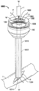
[0016] With reference to FIG. 1, a surgical access assembly configured for use
with a seal
assembly 100 according to an embodiment of the present disclosure is shown
designated
1000. Surgical access assembly 1000 includes proximal and distal ends 1002 and
1004
respectively. A housing 1006 of suitable proportion is located at the proximal
end 1002.
More particularly, the housing 1006 is configured and dimensioned to receive
of one or more
surgical sutures or filaments "F" and/or a surgical object, or objects "I." To
this end, housing
1006 includes an opening 1008 of suitable proportion. Housing 1006 is also
configured and
dimensioned to accommodate seal assembly 100. An access member 1010 extends
distally
from the housing 1006 and is dimensioned for positioning with a percutaneous
access point
"P" formed in a patient's tissue "T", e.g., a patient's knee or shoulder. The
access member
CA 02716240 2010-10-04
1010 defines a passageway 1012 (shown in phantom) that extends longitudinally
through the
access member 1010 and along a longitudinal axis "A." The passageway 1012 is
in
substantial alignment with the opening 1008. The passageway 1012 is configured
and
dimensioned for the internal receipt of one or more surgical filaments "F"
and/or a surgical
object, or objects "I." The access member 1010 defines an opening 1014 at the
distal end
1004 to allow the surgical filaments "F" and the surgical object "I" to pass
therethrough.
[0017] With reference now to FIG. 2, the seal assembly 100 will be discussed.
The seal
assembly 100 includes at least two seal components 102, 104 that are assembled
in a manner
that provides a double layer rotational seal. The seal components 102, 104 may
be formed of
any suitable biocompatible and at least semi-resilient material, and may be
formed through
any suitable method of manufacture, including but not limited to molding,
casting, and
electrical discharge machining (EDM). Examples of suitable materials include,
but are not
limited to elastomeric materials such as natural rubber, synthetic
polyisoprene, butyl rubber,
halogenated butyl rubbers, polybutadiene, styrene-butadiene rubber, nitrile
rubber,
hydrogenated nitrile rubbers, chloroprene rubber, ethylene propylene rubber,
ethylene
propylene diene rubber, epichlorohydrin rubber, polyacrylic rubber, silicone
rubber,
fluorsilicone rubber, fluoroelastomers, perfluoroelastomers, polyether block
amides,
chlorosulfonated polyethylene, ethylene-vinyl acetate, thermoplastic
elastomers,
thermoplastic vulcanizers, thermoplastic polyurethane, thermoplastic olefins,
resilin, elastin,
and polysulfide rubber. Forming the seal components 102, 104 from such
materials permits
the seal components 102, 104 to resiliently accommodate the insertion,
manipulation, and
removal of the surgical filaments "F", as well as surgical objects "I" that
may vary in size.
6
CA 02716240 2010-10-04
[0018] Seal component 102 includes a generally circular configuration having
an outer
diameter "OD1" that allows seal component 102 to securely and movably couple
to seal
component 104. With this purpose in mind, seal components 102 and 104, or
components
associated therewith may be coated with or made from a material that is
relatively slick (e.g.,
PTFE). Seal component 102 includes respective proximal and distal surfaces 108
and 116
connected by an outer segment or generally circumferential sidewall 132. Side
wall 132 may
or may not extend in a general longitudinal direction from either of proximal
and distal
surfaces 108,116. In the embodiment illustrated in FIGS. 1 and 2, an O-ring
106 is
operatively disposed along the proximal surface 108 of seal component 102. O-
ring 106 is
intended to provide a seal against an internal surface 1005 (not shown) at the
proximal end
1002 of the access device 1000 (See FIG. 4). O-ring 106 may be integrally
formed with seal
component 102. Alternatively, O-ring 106 may be configured to seat within a
groove or
channel (not shown) disposed along proximal surface 108. Seal component 102
includes
inner segment 110 having a passage 112 which extends through the seal
component 102.
Passage 112 may includes one or more slits 114, including but not limited to
single-slit
valves, multi-split valves, or apertures or the like configured for the
intended purpose of
substantially limiting the communication of fluids, e.g., saline or
insufflation gas, through the
seal assembly 100 when an object or instrument is inserted therethrough. In
the embodiment
illustrated in FIG. 2, a multi-slit valve configuration is depicted. Passage
112 of the seal
member 110 extends through the seal component 102 and is normally biased
towards a closed
condition (see FIG. 2, for example, e.g., with the slit being substantially
closed) to provide a
substantially fluid-tight seal in the absence of surgical filaments "F" and/or
the surgical
object "I". Seal member 110 is also configured to help minimize the escape of
fluid through
7
CA 02716240 2010-10-04
the seal assembly 100 when the surgical filaments "F" and/or the surgical
object "I" is
inserted therethrough. A distal surface 116 of seal member 102 includes one or
more
structures 118, e.g., raised portion in the form of an annular rib 118 (as
best seen in FIG. 4),
configured to engage one or more corresponding structures, e.g., circular
groove, recess or
channel 120 (described in more detail below), proximally located on seal
component 104.
Rib 118 of seal component 102 engages recess 120 of seal component 104 such
that seal
component 102 is rotatably moveable relative to seal component 104. The rib
118 and/or
recess 120 may be coated with or made from a material that is quite slippery
(e.g., PTFE).
While seal component 102 of the seal assembly 100 is illustrated as
substantially circular in
configuration, it is within the purview of the present disclosure that the
seal component 102
may exhibit any suitable geometrical configuration.
[00191 With continued reference to FIG. 2, seal component 104 is shown. Seal
component
104 may be operably coupled to an internal surface of the housing 1006 by any
suitable
known coupling and/or connecting methods (e.g., press or friction fit,
adhesives, and so
forth). In one embodiment, seal component 104 is secured to housing 1006 in a
manner
preventing rotational movement about longitudinal axis "A". Seal component 104
is
configured to releasably engage seal component 102. To this end, seal
component 104
includes an annular peripheral segment or wall 121 having inner and outer
circumferential
sidewalls, 122, 124, respectively, defining respective inner and outer
diameters "ID" and
"OD2." Inner diameter "ID" of seal component 104 is dimensioned and configured
to
releasably and movably engage seal component 102 such that seal component 102
is rotatable
relative to seal component 104. To this end, the inner diameter "ID" of seal
component 104
is greater than the OD, of seal component 102. Inner sidewall 122 extends
orthogonally from
8
CA 02716240 2010-10-04
an inner surface 126 defining a cavity 140 configured to receive a portion of
seal component
102. As noted above, seal component 104 includes a groove, recess, or recess
120. Recess
120 extends along a periphery of the surface 126. In the embodiment
illustrated in FIG. 2,
recess 120 includes a generally circular configuration and is configured to
releasably engage
circular rib 118. Inner seal segment 128 of seal component 104 has a passage
defined by one
or more slits 134.
[0020] In FIGS. 1 and 2, respective passages 112, 130 of seal components 102,
104 are in
substantial longitudinal alignment, e.g., the legs of slits 114, 134 of first
and second seal
components 102, 104 are aligned. Alternatively, inner seal segments 128 and
110 may be
radially offset from each other whereby the slits 114, 134 are radially
displaced as will be
discussed in greater detail hereinbelow. Seal members 128, 110 of seal
components 104,
102, are configured in substantially the same manner and, as a result, seal
member 128 will
not be described in further detail hereinafter.
[0021] As noted above, seal assembly 100 includes a seal component 102 that is
rotatably
movable relative to seal component 104 when seal component 102 is operatively
engaged
with seal component 104. To this end, in an embodiment illustrated in FIGS. 3
and 4, seal
component 102 may include one or more tactile structures 136 (e.g., posts,
detents, ribs, slits,
slots, etc.) configured to facilitate movement of seal member 102 when the
seal components
102, 104 are in engagement with each other. In the embodiment illustrated in
FIGS. 3 and 4,
tactile structure 136 includes one or more posts 138 (3 posts are shown in the
drawings)
operatively disposed at predetermined locations along proximal surface 108 of
seal
component 102. Posts 138 extend in a generally orthogonal direction from
proximal surface
9
CA 02716240 2010-10-04
108 of seal component 102. As shown in the representative drawings, posts 138
are spaced
apart approximately 120 from each other. Posts 138 may extend through a
corresponding
annular opening 1003 (FIG. 1) in proximal end 1002 of housing 1006. Posts 138
each may
extend a distance sufficient to be manually engaged by the clinician (FIG. 4).
[0022] With reference to FIG. 5, a method of use of the surgical access
assembly 1000
including seal assembly 100 is described in terms of use during the course of
an arthroscopic
procedure. Initially, a fluid, such as saline, is introduced into the surgical
worksite (step 202).
Thereafter, the access member 1010 is positioned within the percutaneous
access point "P"
formed in the patient's tissue "T" (see step 204 and FIG. 1, for example), and
the surgical
object "I" and/or the surgical filament "F" are introduced into the surgical
worksite by
passage through the housing 1006 and the access member 1010 (see step 206 and
FIG. 1, for
example). Either prior to the insertion of the surgical object "I" and/or the
surgical filament
"F" or at any other point during the course of the procedure, the practitioner
may move
and/or rotate (e.g., a clockwise direction) the seal component 102(see step
208). As noted
above, the seal component 102 is rotatable from a first position, seen in FIG.
2, in which the
respective passages 112, 130 of the seal members 110, 128 in substantial
radial alignment,
into a second position, seen in FIG. 3, in which the respective passages 112,
130 of the seal
members 110, 128 are radially offset from one another. Rotating the seal
component 102
relative to seal component 104 interrupts and substantially closes off the
path of any fluid
communicated proximally through the surgical access assembly 1000 (FIG. 1) to
further
minimize leakage of fluid. For example, rotation of the first seal component
relative to the
second seal component may create a tortuous path through the seal components
102, 104 to
minimize fluid leakage. Subsequently, the practitioner can manipulate the
surgical object "I"
CA 02716240 2010-10-04
and/or the surgical filament "F" through the surgical access assembly 1000 to
carry out the
remainder of the procedure (step 210). It is envisioned that housing 1006 and
posts 138 may
have cooperative visual indicia or markings which depicts when the seal
components 102,
104 are rotated where the passages are in substantial alignment. Indicia may
take any form.
In one embodiment, the indicia is in the form of arrows "k", "m" on the
proximal surface of
housing 1006 and on one of posts 138, respectively (see, e.g., FIGS 1 and 3).
Other
variations are also envisioned.
[0023] From the foregoing and with reference to the various figure drawings,
those skilled in
the art will appreciate that certain modifications can also be made to the
present disclosure
without departing from the scope of the same. For example, while seal assembly
100 has
been described herein as being fixedly secured to housing 1006 of access
device 1000, it is
within the purview of the present disclosure to provide seal assembly 100
detachably
mountable to the proximal end of housing 1006 and/or access device 1000. In
this
embodiment, seal assembly may operably couple to access device 1000 (e.g.,
seal component
104 includes an outer diameter OD, that is dimensioned to securely couple or
engage an
interior of housing 1006). Thus, the surgeon can remove seal assembly 100 from
the access
device 1000, for example, at any time during the surgical procedure and,
similarly, mount the
seal assembly 100 to the access device 1000 when desired. In addition, seal
assembly 100
may be readily adapted for mounting to conventional cannulas of differing
structures. The
detachability of seal assembly 100 from access device 1000 or other
conventional cannulas,
for example, is intended to facilitate specimen removal through access device
1000.
[00241 It is contemplated that seal assembly 100 may include a tactile member
(not shown) to
facilitate repositioning of a portion of the seal assembly 100 between the
first and second
11
CA 02716240 2010-10-04
positions. The tactile member can be coupled to either the seal components
102, 104, and
may be configured to depend outwardly from through an opening associated with
the
housing 1006 of the surgical access assembly 1000 such that the practitioner
can manually
manipulate the relative position of the seal components 102, 104.
[0025] It is envisioned that in embodiments of the seal assembly 100, relative
movement
between the seal components 102, 104 may be effectuated in any suitable
manner, including
but not limited to the incorporation of a mechanized assembly, such as a motor
and gear set.
To this end, either or both of the seal components 102, 104 may include
bearings, or any
other suitable structure, to assist in the relative movement of the seal
components 102, 104
between the first and second positions. It is further envisioned that the seal
components 102,
104 may be rotatably biased (with a spring or other suitable biasing
mechanism) toward the
aligned position of FIG. 2 or the non-aligned position of FIG. 3.
[0026] The access assembly may be used in conjunction with a laparoscopic
surgical
procedure performed, e.g., with the peritoneal cavity of the patient. In
accordance with such
procedures, the peritoneal cavity is insufflated and access may be established
with the access
assembly in a manner known in the art, e.g., with an obturator which is
positioned within the
access assembly and advanced to penetrate the peritoneal lining. Thereafter,
the obturator
may be removed leaving the access assembly 100o within the peritoneal body
cavity.
Instruments may be introduced within the access assembly and the seal
components 102, 104
may be manipulated to establish a seal about the surgical instrument.
(0027] While several embodiments of the disclosure have been shown in the
drawings and/or
discussed herein, it is not intended that the disclosure be limited thereto,
as it is intended that
the disclosure be as broad in scope as the art will allow and that the
specification be read
12
CA 02716240 2010-10-04
likewise. Therefore, the above description should not be construed as
limiting, but merely as
exemplifications of particular embodiments. Those skilled in the art will
envision other
modifications within the scope and spirit of the claims appended hereto.
13