Note: Descriptions are shown in the official language in which they were submitted.
CA 02716484 2010-08-20
WO 2009/114048 PCT/US2008/083507
METHOD AND APPARATUS FOR SURFACE ENHANCED RAMAN
SPECTROSCOPY
I3ACKGROtJND
FIELD
[0001] The present technology relates to systems and methods for spectroscopy
analysis. More particularly, embodiments of the technology involve a system
and
method for performing surface enhanced Raman spectroscopy.
RELATED ART
[0002] Surface Enhanced Raman Spectroscopy (SERS), or scattering, is a
technique for analyzing a material to identify components of the material
present at a
surface of the material and other materials that have come in contact with the
surface.
SERS involves exposing the material under test to a monochromatic light source
(such
as a laser) and sensing the light reflected by the material under test.
Characteristics of
the reflected light provide a "fingerprint" of the material, including
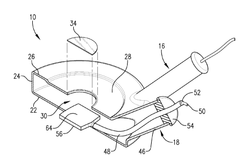
information about
components present in the material. SERS can be used, for example, to detect
and
analyze corrosion taking place at the surface of a metal. This may be useful
in
evaluating the effectiveness of corrosion inhibiting agents.
[0003] Conventional SERS processes involve aligning a light source, such a
laser, with a material to be tested and aligning various light sensors with
the material
to be tested to capture the light reflected off the material. Aligning the
emitter and the
sensors for the conventional SERS processes is an iterative process that can
take
several hours to perform making the process inefficient at best.
[0004] Thus, there is a need for an improved SERS process that does not suffer
ii-om the limitations of conventional SERS processes.
CA 02716484 2010-08-20
WO 2009/114048 PCT/US2008/083507
SUMMARY
[0005] Embodiments of the present invention address the above-mentioned
limitations and provide a distinct advance in the art of.
[0006] According to a first embodiment of the invention, a test cell comprises
a
test chamber at least partially enclosed by a wall, the wall including a
window. The
test cell further comprises a test fluid within the test chamber, and a test
material
within the test chamber, at least a portion of the test material in contact
with the test
fluid and at least a portion of the test material in optical register with the
window. The
test cell further comprises a first conductive element in electrical
communication with
the test fluid and separated from the test material by a space, the first
conductive
element extending to an outside of the cell, and a second conductive element
in
electrical communication with the test material and extending to the outside
of the
cell.
[0007] According to a second embodiment of the invention, a test cell with an
internal test chamber separated from an outside of the cell by a wall
comprises a top
planar segment of the wall including a substantially transparent portion, a
test fluid
within the test chamber, and a test material within the test chamber and
immersed in
the test fluid, the test material partially coated with an electrically
insulating material
such that only a single exposed face of the test material is in contact with
the test fluid,
wherein the exposed face is in optical register with the substantially
transparent
portion of the wall. The test cell further comprises a first conductive
element in
electrical communication with the test fluid and extending to the outside of
the cell, a
second conductive element with a first end in contact with the test fluid and
a second
end extending to the outside of the cell. The first end of the second
conductive
element is separated from the test material by a space, and the second
conductive
element is covered with an electrically insulating material preventing the
second
conductive element from contacting the test fluid. A third conductive element
is in
electrical communication with the test material and extends to the outside of
the cell.
[0008] According to a third embodiment of the invention, a method of
performing a spectroscopy analysis comprises adding a test fluid to an
internal
chamber of a cell; placing a test material in the cell such that the test
material is at
2
CA 02716484 2010-08-20
WO 2009/114048 PCT/US2008/083507
least partially in contact with the test fluid; aligning a substantially
transparent portion
of the cell with an optical component of a spectroscopy instrument; and
performing
the spectroscopy analysis on the test material by exposing the test material
to light
generated by the emitter and capturing light reflected from the test material
using the
optical component.
[0009] According to a fourth embodiment of the invention, a method of
performing a spectroscopy analysis comprises adding a test fluid to an
internal
chamber of a cell; placing a test material in the cell such that the test
material is
submersed in the test fluid, the test material including a first conductive
element
extending to an outside of the cell, wherein the first conductive element and
the test
material are coated with an electrical insulating material such that only a
single face of
the test material is exposed to the test fluid; aligning said test material
with a
substantially transparent portion of said cell; aligning said substantially
transparent
portion of said cell with an optical component of a spectroscopy instrument,
said
optical component including a light emitter and a light sensor; applying an
electric
potential between said test material and a second conductive element, said
second
conductive element being in contact with said test fluid and separated from
said test
material by a space; and performing said spectroscopy analysis on said test
material
by exposing said test material to light generated by said emitter and
capturing light
reflected from said test material using said optical component.
[0010] This summary is provided to introduce a selection of concepts in a
simplified form that are further described below in the detailed description.
This
summary is not intended to identify key features or essential features of the
claimed
subject matter, nor is it intended to be used to limit the scope of the
claimed subject
matter.
[0011] Other aspects and advantages of the present invention will be apparent
from the following detailed description of the preferred embodiments and the
accompanying drawing figures.
3
CA 02716484 2010-08-20
WO 2009/114048 PCT/US2008/083507
BRIEF DESCRIPTION OF THE DRAWING FIGURES
[0012] A preferred embodiment of the present technology is described in detail
below with reference to the attached drawing figures, wherein:
[0013] FIG. I is a perspective view of a test cell constructed according to
principles of the present teachings and illustrating a test material placed
within the
cell;
[0014] FIG. 2 is a plan view of the cell of FIG. 1;
[0015] FIG. 3 is a cross-sectional view of the cell of FIG. 1 taken along line
3-
3 of FIG. 2;
[0016] FIG. 4 is a cross-sectional view of the cell of FIG. 1 taken along line
4-
4 of FIG. 2;
[0017] FIG. 5 is a side elevation view of the cell of FIG. I illustrating a
perspective of FIG. 6;
[0018] FIG. 6 is a cross-sectional view of the cell of FIG. 1 taken along line
6-
6 of FIG. 5; and
[0019] FIG. 7 is a schematic diagram of a spectroscopy system including the
cell of FIG. I and a spectroscopy instrument.
[0020] The drawing figures do not limit the present invention to the specific
embodiments disclosed and described herein. The drawings are not necessarily
to
scale, emphasis instead being placed upon clearly illustrating the principles
of the
invention.
DETAILED DESCRIPTION
[0021] The following detailed description of the present technology references
the accompanying drawings that illustrate specific embodiments in which the
technology may be practiced. The embodiments are intended to describe aspects
of
the technology in sufficient detail to enable those skilled in the art to
practice the
invention. Other embodiments can be utilized and changes can be made without
departing from the scope of the present teachings. The following detailed
description
is, therefore, not to be taken in a limiting sense. The scope of the present
invention is
4
CA 02716484 2010-08-20
WO 2009/114048 PCT/US2008/083507
defined only by the appended claims, along with the full scope of equivalents
to which
such claims are entitled.
[0022] A test cell is illustrated in Figs. 1-6 and designated generally by the
reference numeral 10. The cell 10 may be used in spectroscopy analyses,
including
SERS, and generally includes a cell body 12 with a window 14, a first
electrode tube
16. a second electrode tube 18, and a third electrode tube 20.
[0023] The body 12 may be cylindrical in shape (as illustrated), comprising a
circular bottom wall 22, an annular side wall 24, and a circular top wall 26.
The top
wall 26 presents a recessed portion 28 that includes the window 14. The bottom
wall
22, side wall 24, and top wall 26 may form a single, integral wall that
defines an
internal test chamber 30 that is adapted to hold a test fluid 32, explained
below in
greater detail. The walls 22,24,26 may be constructed of substantially any
suitably
durable material including glass, plastic, metal, or the like. Constructing
the walls
22,24,26 of a substantially transparent material may be desirable to enable a
user to
view the contents of the cell 10 from various angles. In a particular
embodiment, the
walls 22,24,26 are constructed of PYREX.
[0024] While the body 12 is illustrated and described as being generally
cylindrical in shape, embodiments of the invention may present other, equally-
preferred shapes without departing from the spirit or scope of the present
teachings.
By way of example, the body 12 may present a rectangular, ovular, or arbitrary
shape.
[0025] The recessed portion 28 is a generally planar region of the top wall 26
surrounding and including the window 14. While the recessed portion 28 is
illustrated
as presenting a circular pattern, the present teachings are not so limited and
the
recessed portion 28 may present other, equally-preferred patterns including,
for
example, rectangular patterns or arbitrarily-shaped patterns. The recessed
portion 28
is generally parallel with the non-recessed portion of the top wall 26, though
offset by
a distance within the range of from about 0.5mm to about 3.5mm or within the
range
of from about 1.0mm to about 3.0mm. More particularly, the recessed portion 28
may
he offset from the non-recessed portion of the top wall 26 a distance of about
1.5mm,
about 2.0mm, or about 2.5mm. The recessed portion 28 may be useful, for
example,
CA 02716484 2010-08-20
WO 2009/114048 PCT/US2008/083507
to facilitate spectroscopy analysis by accommodating placement of an optical
component proximate the window 14.
[0026] The window 14 is a region that allows light to pass therethrough with
minimal scattering, and thus is transparent or substantially transparent. The
window
may be an uncovered aperture in the top wall 26, or may include a thin plate
or sheet
of transparent material separating the test chamber 30 from outside the cell
10. By
way of example, the window 14 may include a hole in the top wall 26 and a thin
sheet
of transparent material 34, such as a thin sheet of glass or plastic similar
to a
microscope slide cover, secured to a top or outer surface of the top wall 26.
The thin
sheet of transparent material 34 may be separate from the top wall 26 and
secured
thereto using an adhesive, such as a resin. Alternatively, the thin sheet of
transparent
material 34 may be an integral part of the top wall 26. The sheet of
transparent
material 34 may be substantially thinner than the wall 26, as explained below
in
greater detail.
[0027] The window 14 may be circular (as illustrated) and may have a diameter
within the range of from about 0.5cm to about 2.5cm or within the range of
from
about 1.0cm to about 2.0cm. More particularly, the diameter of the window 14
may
be about 1.3em, about 1.5cm, or about 1.7cm. The window 14 need not be
circular
but may present other shapes, including, for example, rectangular and
triangular
shapes. Regardless of the particular shape of the window 14, it may present an
area
within the range of from about 0.10cm2 to about 5.Ocm2 or within the range of
from
about 1.0cm2 to about 4.Ocm2. More particularly, the are of the window may be
about
1.5 cm2, about 2.0 cm2, about 2.5 cm2 , about 3.0 cm2, or about 3.5 cm2.
[0028] The bottom wall 22, side wall 24, and top wall 26 may each present a
thickness within the range of from about 0.3mm to about 1.7mm, within the
range of
from about 0.5mm to about 1.5mm, or within the range of from about 0.7mm to
about
1.3mm. More particularly, the bottom wall 22, side wall 24, and top wall 26
may each
present a thickness of about 0.9mm, about 1.0mm, or about 1.1 mm. The window
14
may present a thickness within the range of from about O.lmm to about 0.3mm or
from about 0.15mm to about 0.25mm. More particularly, the window 14 may be
about 0.17mm thick, about 0.20mm thick, or about 0.23mm thick.
6
CA 02716484 2010-08-20
WO 2009/114048 PCT/US2008/083507
[0029] A diameter of the annular side wall 24 may be within the range of from
about 2.0cm to about 10.0em, within the range of from about 4.0cm to about
8.0cm, or
within the range of from about 5.0cm to about 7.0cm. More particularly, the
diameter
of the annular wall 24 may be about 5.7cm, about 6.0cm, or about 6.3cm. A
volume
of the test chamber 30 may be within the range of from about 20cm3 to about
60cm3
or from about 30cm3 to about 50cm3. More particularly, the volume of the test
chamber 30 may be about 35cm3, about 40cm3, or about 45cm3.
[0030] The first electrode tube 16 houses a reference electrode including a
conductive element 36 and a reference fluid 38. An outer tubular wall 40 and
an end
cap 42 of the tube 16 define an internal chamber that retains the reference
fluid 38. A
salt bridge 44 separates the reference fluid 38 from the test fluid 32 in the
test chamber
30.
[0031] The reference fluid 38 provides a known electrochemical potential used
as a base or background potential when, for example, applying an electric
potential to
a test material within the cell 10. The reference fluid 38 may be a salt
solution that
includes, for example, silver chloride, potassium chloride, or silver nitrate.
The salt
bridge 44 provides a physical barrier between the reference fluid 38 of the
tube 16 and
the test fluid 32 of the internal test chamber 30 while allowing electron
migration
between the reference fluid 38 and the test fluid 32. The salt bridge 44 may
include
the same salt that is used in the reference fluid 38. The reference fluid 38
and the salt
bridge 44 may be conventional in nature.
[0032] The conductive element 36 may be silver or platinum wire or foil
extending from a location within the tube 16 proximate the salt bridge 44
through the
end cap 42 to provide means for placing an external apparatus, such as a
potentiostat,
in electrical communication with the reference fluid 38. Thus, the conductive
element
36 is in electrical communication with the reference fluid 38 but does not
contact the
salt bridge 44.
[0033] A first end of the electrode tube 16 attaches to or is integral with
the cell
body 12 and a second end of the electrode tube 16 (including the end cap 42)
extends
generally upwardly and outwardly from the cell body 12. A diameter of the tube
16
may be within the range of from about 0.5cm to about 1.5cm or within the range
of
7
CA 02716484 2010-08-20
WO 2009/114048 PCT/US2008/083507
from about 0.7cm to about 1.3cm. More particularly, the diameter of the tube
16 may
be about 0.85cm, about 0.90cm, or about 0.95cm. A length of the tube 16 may be
within the range of from about 1.Ocm to about 5.Oem or within the range of
from
about 2.Ocm to about 4.0cm. More particularly, the length of the tube 16 may
be
about 2.5cm, about 3.0cm, or about 3.5cm.
[0034] The second electrode tube 18 is defined by a tubular wall 46 that
houses
a working electrode 48 including, for example, a wire 50 encapsulated in
electrically
insulating material 52 extending from an outside of the tube 18, through an
end cap
54, to a test material 56. The test material 56 may be a specimen of any
material that
is the target of the analysis or test and may be, for example, a piece of
metal of the
kind used in a pipeline or a holding tank. The test material 56 is
electrically and
physically connected to the wire 50 such that the test material 56 may be
inserted into
the test chamber 30 by inserting the material 56 and the wire 50 through a
mouth of
the second electrode tube 18.
[0035] A first end of the electrode tube 18 attaches to or is integral with
the cell
body 12 and a second end of the electrode tube 18 extends generally upwardly
and
outwardly from the cell body 12. A diameter of the tube 18 may be within the
range
of from about 0.5cm to about 2.0cm or within the range of from about l.Oem to
about
1.5cm. More particularly, the diameter of the tube 18 may be about 1.2cm,
about
1.3cm, or about 1.4cm. A length of the tube 18 may be within the range of from
about
1.0cm to about 5.0cm or within the range of from about 2.0cm to about 4.Ocm.
More
particularly, the length of the tube 18 may be about 2.5cm, about 3.0cm, or
about
3.5cm.
[0036] The test material 56 is preferably planar and may present substantially
any shape, including, for example, a rectangular or circular shape. If the
material 56
is rectangular, a length and a width of the material 56 may each be within the
range of
from about I.Omm to about 15.0mm or within the range of from about 2.0mm to
about
14.0mm. More particularly, the length and the width of the material 56 may
each be
about 9.5mm, about 10.0mm, or about 10.5mm. A depth or thickness of the
material
56 may be within the range of from about 0.5mm to about 5.0mm or within the
range
8
CA 02716484 2010-08-20
WO 2009/114048 PCT/US2008/083507
of from about 0.6mm to about 4.5mm. More particularly, the thickness of the
material
56 may be about 2.5mm, about 3.0mm, or about 3.5mm.
[0037] The third electrode tube 20 houses a counter electrode including a
conductive element 58. An outer tubular wall 60 of the tube 20 holds an
electrically
insulating retaining material 62. The retaining material 62 includes an axial
through-
hole that receives and supports the conductive element 58. The conductive
element 58
may include a platinum wire that extends from an outside of the tube 20 into
the test
chamber 30 and in contact with the test fluid 32.
[0038] A diameter of the tube 20 may be within the range of from about 0.5cm
to about 1.5cm or within the range of from about 0.7cm to about 1.3cm. More
particularly, the diameter of the tube 14 may be about 0.85cm, about 0.90cm,
or about
0.95cm. A length of the tube 16 may be within the range of from about 1.0cm to
about 5.0em or within the range of from about 2.0em to about 4.0cm. More
particularly, the length of the tube 16 may be about 2.5cm, about 3.0em, or
about
3.5cm.
[0039] Portions of the test material 56 may be substantially entirely coated
with
an electrically and chemically insulating material such that only a face 64 of
the test
material 56 is exposed to, and in contact with, the test fluid 32. Thus, a
face opposite
the 1ace 64, as well as various sides or edges, may be coated with the
electrically
insulating material. Exposing only the face 64 to the test fluid 32
facilitates
determining with precision the total amount of surface area of the test
material 56
exposed to the test fluid 32, which may be helpful or required in various
spectroscopy
analyses.
[0040] The first electrode tube 16 and the second electrode tube 18 may be
radially separated by a first angle a, and the second electrode tube 18 and
the third
electrode tube 20 may be radially separated by a second angel b. The first
angle a and
the second angle b may each be within the range of from about 10 to about 170
or
from about 30 to about 150 . More particularly, the first angle a and the
second angle
b may each be about 60 , about 70 , or about 80 . As explained above, each of
the
tubes 16,18,20 extends upwardly and outwardly relative to the body 12 of the
cell 10.
An upward angle c of each of the tubes 16,18,20 relative to the body 12 may be
within
9
CA 02716484 2010-08-20
WO 2009/114048 PCT/US2008/083507
the range of from about 10 to about 80 or within the range of from about 30
to about
70 . More particularly, the upward angle of each of the tubes 16,18,20 may be
about
400
, about 45 , or about 50 .
(0041] The cell 10 may be used in spectroscopy analysis, such as surface
enhanced Raman spectroscopy. A spectroscopy instrument 70 including a
potentiostat
72 may be used with the cell 10 to perform the analyses as illustrated in the
schematic
diagram of Fig. 7. The potentiostat 72 is connected to the conductive elements
36, 50,
and 58. An optical component 74, including a monochromatic light source 76,
such as
a laser, and an optical sensor 78, is positioned relative to the cell 10 to be
generally in
register with the window 14 so that light emitted from the light source 76
strikes the
test material 56 and is reflected back toward the optical component 74
according to
principles of spectroscopy.
[0042] The cell 10 is first positioned relative to the light source 76 so that
light
generated by the light source 76 is reflected by the test material 50 and
focused on the
light sensor 78. The step of positioning the light source 76 and the cell 10
relative to
one another may take a few minutes. This presents a substantial advantage to
the
conventional methods of preparing a spectroscopy system which include manually
moving emitters and sensors and could take hours to complete.
[0043] When the cell 10 is aligned with the optical component 74, the
potentiostat 72 is electrically connected to the conductive elements 36,50,58.
The
instrument 70 measures the reference voltage on the conductive element 36 of
the
reference electrode and applies an electric potential to the test material 56
by applying
an electric potential across the conductive element 50 of the working
electrode and the
conductive element 58 of the counter electrode. The precise voltage applied
across
the working and counter electrodes may vary from one application to another.
[0044] According to an exemplary application, an electric potential of 1200mV
is applies across the working and counter electrodes such that the working
electrode is
at approximately the same potential as the reference electrode, and a
potential of -
1200mV is applied to the counter electrode relative to the working electrode.
A SERS
spectrum is captured at each of several pre-determined intervals by exposing
the test
material 56 to light generated by the light source 76, detecting the light
reflected from
CA 02716484 2010-08-20
WO 2009/114048 PCT/US2008/083507
the test material 56 with the optical sensor 78, and analyzing the light
detected by the
optical sensor 78 to gather information about the test material 56. By way of
example,
a new SERS spectrum may be captured every one-hundred seconds wherein the
potential across the working and counter electrodes is increased by
1.OmV/second
until the potential across the conductive elements 50 and 58 is -300mV.
[0045] The present technology can be used to generate SERS spectra using
relatively low-power optics. For example, the light source 76 may be a laser
emitter
operable to generate laser light at a power of between 30mW and 80mW.
[0046] Although the invention has been described with reference to the
embodiments illustrated in the attached drawing figures, it is noted that
equivalents
may be employed and substitutions made herein without departing from the scope
of
the invention as recited in the claims. For example, the particular form or
function of
the various attachment elements is not important to the present technology,
and the
attachment elements may present alternative shapes and sizes with equally-
preferred
results.
[0047] As used herein, the terms "a," "an," "the," and "said" means one or
more.
[0048] As used herein, the terms "comprising," "comprises," and "comprise"
are open-ended transition terms used to transition from a subject recited
before the
term to one or elements recited after the term, where the element or elements
listed
after the transition term are not necessarily the only elements that make up
of the
subject.
[0049] As used herein, the terms "containing," "contains," and "contain" have
the same open-ended meaning as "comprising," "comprises," and "comprise,"
provided below.
[0050] As used herein, the terms "having," "has," and "have" have the same
open-ended meaning as "comprising," "comprises," and "comprise," provided
above
[0051] As used herein, the terms "including," "includes," and "include" have
the same open-ended meaning as "comprising," "comprises," and "comprise,"
provided above.
11
CA 02716484 2010-08-20
WO 2009/114048 PCT/US2008/083507
[0052] As used herein, a "conductor," "conductive element," or conductive
material" is a material with an electrical resistivity of less than about 1 x
10-3 Qm and
more preferably less than about 1 x 10⁻⁵Qm.
[0053] As used herein, an "insulator," "insulating element," or "insulating
material" is a material with an electrical resistivity of more than about
lOOQm and
more preferably more than about 1 x 10³SZm.
[0054] Having thus described various embodiments of the invention, what is
claimed as new and desired to be protected by Letters Patent includes the
following:
12