Note: Descriptions are shown in the official language in which they were submitted.
CA 02716614 2010-10-05
DIRECT FIRED CONDUCTIVE SUBTERRANEAN HEATING SYSTEM
Field
The invention relates to apparatus and method for production of oil from a
subterranean
formation.
Background
Many reservoirs containing vast quantities of oil including heavy oil and
bitumen have been
discovered in subterranean formations. However, the recovery of oil from some
subterranean
formations has been very difficult due to the relatively high viscosity of the
oil. In particular,
when a production well is drilled into a subterranean formation to recover oil
residing therein,
often little or no oil flows into the production well. To overcome this
problem, various thermal
recovery techniques have been used to decrease the viscosity of the oil,
thereby making the
recovery of the oil easier. However, these techniques can be very energy
intensive and can
significantly change the pressure conditions in the wellbore.
A need therefore exists to provide heat to a subterranean formation and
thereby improve the
production of oil from the subterranean formation.
W S Legal\065151 \00002\6340527v 1
CA 02716614 2010-10-05
2
Summary
In accordance with a broad aspect of the present invention, there is provided
an apparatus for
heating a subterranean formation to facilitate production of oil therefrom,
the apparatus
comprising: a downhole ignition area; a conduit to deliver oxygen, a
combustible fluid or a
combination thereof, to the down hole ignition area; and return conduit that
recovers flue gas
from the down hole ignition area.
In accordance with another broad aspect of the present invention, there is
provided a method for
heating subterranean formations, the method comprising: employing an apparatus
installed in a
subterranean formation including: a down hole ignition area; a conduit to
deliver oxygen, a
combustible fluid or a combination thereof, to the down hole ignition burner
head; and a return
conduit that recovers flue gas from the down hole ignition burner head;
igniting a mixture of
oxygen and combustible fluid down hole to combust and produce heat and a flue
gas; the heat
produced conductively heats the subterranean formation; and the flue gas from
the ignition area
is returned to the surface.
In accordance with another broad aspect of the present invention, there is
provided a method for
heating a subterranean formation comprising: igniting a mixture of oxygen and
a combustible
fluid in a wellbore to combust and produce heat and a flue gas, the heat
conductively heating the
subterranean formation and the flue gas being returned to a surface location,
the mixture of
oxygen and combustible fluid and the flue gas being isolated from contact with
the subterranean
formation.
It is to be understood that other aspects of the present invention will become
readily apparent to
those skilled in the art from the following detailed description, wherein
various embodiments of
the invention are shown and described by way of illustration. As will be
realized, the invention
is capable for other and different embodiments and its several details are
capable of modification
in various other respects, all without departing from the spirit and scope of
the present invention.
Accordingly the drawings and detailed description are to be regarded as
illustrative in nature and
not as restrictive.
WS Legal\065151 \00002\6340527v 1
CA 02716614 2010-10-05
3
Brief Description of the Drawings
Referring to the drawings, several aspects of the present invention are
illustrated by way of
example, and not by way of limitation, in detail in the figures, wherein:
Figure 1: a schematic illustration of a possible embodiment of the invention;
Figure 2: a schematic illustration of a possible embodiment of the invention;
Figure 3: a schematic illustration of a possible embodiment of the invention;
and
Figure 4: a sectional view through one treatment string useful in the present
invention.
Description of Various Embodiments
The detailed description set forth below in connection with the appended
drawings is intended as
a description of various embodiments of the present invention and is not
intended to represent
the only embodiments contemplated by the inventor. The detailed description
includes specific
details for the purpose of providing a comprehensive understanding of the
present invention.
However, it will be apparent to those skilled in the art that the present
invention may be practiced
without these specific details.
In one embodiment of the present invention, as shown in Figure 1, an apparatus
may be installed
in a wellbore in thermal proximity to subterranean formation 10 containing
oil. The apparatus
may provide a combustible mixture of oxygen and a combustible fluid through a
system of
conduits to the wellbore, which is ignited in the wellbore to combust and
generate thermal
energy. The combustible mixture of oxygen and combustible fluid may continue
to be supplied
to the formation to continue generating thermal energy until such generation
of thermal energy is
no longer needed. The apparatus may include therefore a conduit 14 extending
from surface 15
for conducting oxygen from a source 16 and a fuel conduit 18 extending from
surface for
conducting the combustible fluid from a source 20.
The oxygen may most reasonably be in the form of air and source 16 may
therefore include an
inlet from the surface atmosphere. Of course, other oxygen sources, such as
compressed
supplies, etc. would also work well. The combustible fluid may be selected
from any gas or
W S Legal\065151 \00002\6340527v 1
CA 02716614 2010-10-05
4
liquid that is combustible to form thermal energy. Selection of the
combustible fluid may
consider cost, availability and the tendency for fouling (the cleanliness of
the burn). Of course,
natural gas may be readily available and generates a clean burn and,
therefore, works well for
this purpose. However, other combustibles such as propane, diesel and others
gases and liquids.
The sources 16, 20 may include pumps, compressors, lines, tanks, etc., as will
be appreciated.
The surface equipment, however, is likely to generate a small foot print.
The conduits 14, 18, terminate downhole and the oxygen and combustible fluid
are allowed to
mix in the wellbore in an ignition area 22 where the generation of thermal
energy is desired.
Generally, the oxygen and combustible fluid are maintained separate
substantially until they
reach area 22 in order to prevent burn back. Ignition may occur in various
ways. For example,
ignition may be achieved by a flame generated at or adjacent surface which
travels to area 22.
However, this may complicate the operation. In one embodiment, for example, an
igniter 24
may be positioned in or adjacent area 22. The igniter may take various forms,
such as a spark
generator, pilot, etc. In some cases, operation of the igniter may only be
required once to initiate
the operation of the apparatus. However, in some other cases, the igniter may
be employed from
time to time to restart, or ensure continued, combustion operations.
The ignition generates combustion products including a flame 25, which
generates thermal
energy. The flame will be generated downstream of the igniter in area 22.
The thermal energy generated may conductively heat the surrounding
subterranean formation to
facilitate production of the desired products from the subterranean formation.
The generated
thermal energy may directly heat oil products and/or may heat other formation
fluids to
indirectly heat oil products in the formation. For example, the generated
thermal energy may
conduct out of the apparatus and generate steam from surrounding water, which
in turn heats oil
products for production thereof.
The apparatus may further include a flue gas evacuation conduit 26 that
provides for the
evacuation of flue gas, arrows F, from combustion of the oxygen and
combustible fluid within
the apparatus. The conduit 26 extends from area 22 and may also provide for
some heat
conduction. In fact, as will be appreciated, there may be no well defined
division between area
W S Legal\065151\00002\6340527v1
CA 02716614 2010-10-05
22 and conduit 26. Conduit 26 provides a passage of flue gas to an appropriate
handling area.
Generally, conduit will extend to surface and flue gas will be conducted to
surface for handling.
The apparatus may provide a closed system such that oxygen, combustible fluid
and combustion
products, including the flame and the flue gas, all remain isolated from the
formation. In such an
embodiment, the apparatus may include an outer liner 28 which contains, and
may in part define,
the inner components of the apparatus, including conduits 14, 18, 26 and
provides a substantially
fluid tight outer enclosure, while permitting thermal conduction therethrough
to the formation.
In one embodiment, the outer liner may be formed of a tubular string of liner
(also known as
casing) joints.
Because the apparatus may provide a closed system, it does not significantly
affect the pressure
of the formation. As such, it may have a wide range of applications, even in
formations close to
the surface and/or those with questionable or no cap rock. In one embodiment,
for example, the
apparatus may be useful at depths of 60 to 120 meters, at which the use of
some systems that
have fluid communication with the formation may not be permitted.
The thermal energy provided by the apparatus heats the oil in the formation,
thereby allowing it
to flow for production thereof. Production may be through a producing well.
Alternately, outer
liner 28 may be opened to permit flow therethrough, as by removing conduits 14
and 18 and
perforating the liner.
The apparatus may include a control system. For example, the flows of oxygen
and combustible
fluid to be mixed and ignited can be regulated to control the amount of heat
produced. In one
embodiment, the apparatus may contain one or more valves that regulate the
flow of the
combustion gasses. These valves may be positioned at various locations along
the apparatus.
The control system may further include one or more sensors to provide
information on process
conditions. As shown in Figure 2, for example, a control system may include
one or more of. a
flow regulator 130, such as, for example, a throttling valve, for controlling
flow through oxygen
conduit 114, a flow regulator 132, such as, for example, a throttling valve,
for controlling flow
through fuel conduit 118, a temperature sensor 134 at a position downhole to
detect process
temperature and a flue gas monitor 138 for monitoring flue gas
characteristics, such as content,
temperature, flow rate, etc. The temperature and/or flue gas condition
information may be
W S Legal\065151 \00002\6340527v 1
CA 02716614 2010-10-05
6
communicated to controllers such as directly on regulator 130 and/or regulator
132 or to a
control location, such as a surface monitor 136, which indirectly or directly
communicates 137 to
regulator 130 and/or regulator 132.
Control system components and processes may vary depending on a number of
factors, including
process conditions, familiarity with apparatus function, etc. For example,
during initial
operations, there may be redundancy of temperature sensors and flue gas
monitors. However,
over time, it may be that these redundancies are reduced or eliminated.
The apparatus may further include a flue gas injection system. For example, if
desired, the flue
gas generated in area 122 can be recovered, in whole or in part, from conduit
126 at surface 115,
and pumped back downhole. In one embodiment, therefore, the apparatus may
include a flue gas
handling system 140, such as for example, including one or more of a
compressor, a pump, etc.,
to condition at least some of the returning flue gas for injection downhole
and direct the flue gas,
arrows Fi, into a flue gas injection conduit 142. In one embodiment, the flue
gas may be mixed
with solvents and the flue gas/solvent mixture may be injected downhole to
further facilitate
production of oil products. Solvents may be added from a solvent source 144
associated with the
handling system 140. Suitable solvents may be known to those skilled in the
art and may
include, for example, propane.
The conduit may extend into a formation of interest. In one embodiment,
conduit 142 may
extend alongside the outer liner to access the same formation 110 in which the
direct heating is
occurring. Conduit 142 may include openings 145 through its walls, such that
the recovered flue
gas, and possibly entrained solvent, may directly access the formation through
the openings in
the flue gas injection conduit. Injection of flue gas, with or without
solvent, may provide for
enhanced environmental controls and may further facilitate production of the
desired oil products
from the subterranean formation.
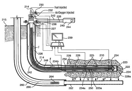
With reference to Figure 3, another apparatus is shown for installation in a
wellbore in thermal
proximity to a subterranean formation 210. The apparatus provides oxygen and a
combustible
fluid through conduits 214, 218 to the wellbore, where the oxygen and
combustible fluid is
mixed and ignited. The resulting combustion generates thermal energy in the
wellbore, which
W S Legal\06 5151 \00002\6340527v 1
CA 02716614 2010-10-05
7
conducts to the formation to heat, directly or indirectly, the oil of the
formation and to facilitate
production thereof.
The oxygen may be in the form of air and the combustible may be selected from
any gas or
liquid that is combustible to form thermal energy. Selection of the
combustible fluid may
consider cost, availability and the tendency for fouling (the cleanliness of
the burn). Of course,
natural gas may be readily available and generates a clean burn and,
therefore, works well for
this purpose. However, other combustibles may also or alternatively be
employed such as
propane, diesel and others gases and liquids. The sources may include pumps,
compressors,
lines, tanks, etc., as will be appreciated. The surface equipment, however, is
likely to generate a
small foot print.
The conduits 214, 218 terminate in the wellbore and the oxygen and combustible
fluid conveyed
therethrough are allowed to mix in area 222. Generally, the oxygen and the
combustible fluid
are maintained separate until they reach area 222 in order to prevent burn
back. A fuel handler
223 may be provided in area 222 to ready the fuel for combustion thereof. Fuel
handler 223 may
take various forms depending on the characteristics of the combustible fluid.
For example, the
fuel handler may include fluid outlets, nozzles, back flow regulators, mixers,
etc. For example, if
the combustible fluid is a liquid, the fuel handler may include, for example,
an atomizer and a
mixer to mix the atomized liquid and the oxygen. If the combustible fluid is a
gas, the fuel
handler may include, for example, nozzles for outlet of the gasses and a
mixer. In one
embodiment, for example, fuel handler may include one or more baffles
positioned in area 222.
A baffle arrangement creates turbulence in the fluids passing thereby to
facilitate mixing thereof
in preparation for ignition and also reduces the chances of burn back.
Ignition of the fuel mixture may occur in various ways. In one embodiment, for
example, an
igniter 224 may be positioned in or adjacent area 222. The igniter may take
various forms, such
as a spark generator, pilot, etc. In this embodiment, igniter 224 is
electrically powered through
an electrical connection, for example, extending from surface. Ignition of the
fuel mixture
generates a flame 225.
The apparatus may further include a flue gas evacuation conduit 226 that will
initially
accommodate the flame and thereafter provides for the evacuation of flue gas,
arrows F, from
WS Legal\065151 \00002\6340527v 1
CA 02716614 2010-10-05
8
combustion of the oxygen and combustible fluid within the apparatus. The
conduit 226 provides
a passage of flue gas to an appropriate handling area. Generally, flue gas
will be conducted to
surface 215 for handling. In one embodiment, to control flue gas evacuation, a
valve 227 is
provided to act as a damper to control flow through conduit 226. Valve 227 may
be adjusted to
regulate the flue gas evacuation rate, which may control residence time and
reduce the
generation of a vacuum effect by up drafting. If the valve is adjusted to
restrict the flow rate of
flue gas through conduit, for example, residence time of the flue gas in the
well may be increased
such that the burn may be affected and the latent heat of the flue gas may be
conducted to the
formation. If valve 227 is adjusted to further open the conduit to fluid flow,
the flue gas may
evacuate at an increased rate from the well, which may lower the temperature
in the well and
affect the burn.
The apparatus may provide a closed system such that oxygen, combustible fluid
and combustion
products, including the flame and the flue gas, remain isolated and out of
contact from the
formation. In such an embodiment, the apparatus may include an outer liner 228
which contains,
and may form in part, the inner components of the apparatus, including
conduits 214, 218, 226
and provides a substantially fluid tight outer enclosure, while permitting
thermal conduction
therethrough to the formation.
One useful treatment apparatus is shown, for example, in Figures 3 and 4. The
illustrated
treatment apparatus, along its downhole treatment section includes an outer
liner 228, an
intermediate tubing string 246 extending along the inner bore of the outer
liner and an inner
tubing string 248 extending along the inner bore of the intermediate tubing
string. Outer liner
228 includes an end wall 228a and strings 246, 248 terminate within the outer
liner. The outer
liner thus forms an outer enclosure and defines the outer limits of the
wellbore installation.
The tubing-in-tubing arrangement creates three fluid flow spaces: the first
through inner bore
defined within inner walls 248a of tubing string, the second between the outer
wall of tubing
string 248 and inner wall 246a of intermediate tubing string 246 and the third
flow space
between the outer wall 246b of intermediate tubing string 246 and the inner
wall of outer liner
228. The flow spaces define area 222 and define conduits 214, 218, 226 for
passage
therethrough of the oxygen, the combustible fluid and the flue gas.
W S Legal\06 5151 \00002\6340527v 1
CA 02716614 2010-10-05
9
Since the heat of combustion is to be conducted through the apparatus into the
formation, the
combustion reaction area 222 and flue gas conduit 226 most reasonably are
placed in the flow
passage between the outer wall 246b of intermediate tubing string 246 and the
inner wall of outer
liner 228. As such, the thermal energy is generated, and the products of
combustion flow,
directly in contact with outer liner 228 such that the heat can conduct
directly therethrough to the
formation.
The oxygen and combustible fluid can pass through the first and second flow
passages. In one
embodiment, the space between the outer wall of tubing string 248 and inner
wall 246a of
intermediate tubing string 246 may form conduit 214 for oxygen and the
combustible fluid may
be conveyed downhole through the bore of inner tubing string 248.
As noted previously, the oxygen may be in the form of air. The air flow may
provide an
insulative and/or a cooling effect between the high temperature conditions in
conduit 226 and
inner tubing string 248. As such, it may be of interest to position more heat
sensitive
components, such as electrical lines, along or through inner tubing string
248.
Spacers may be employed to maintain the spacing between the strings and
between the
intermediate string and the outer liner, if desired.
In one embodiment, inner string 248 and possibly also intermediate string 246
may be
independently trippable relative to outer liner 228. For example, inner string
248 and possibly
also intermediate string 246 may be removable from outer string 228, while the
outer string
remains in the well. As such, it may be desirable to mount fatigable and/or
replaceable
mechanisms on the strings 248 or 246. In one embodiment, for example, inner
string 248 is
formed to be removable and replaceable from within intermediate string 246 and
at least some
components including one or both of sensors, electrical conductors, igniter
224 and fluid handler
223 are mounted on (secured to or embedded in the material of) the string and
can be withdrawn
from the well with the inner string, for inspection, replacement, or repair.
Alternately, at least
some components can be engageable by strings 246 or 248 such that they can be
independently
mounted downhole but engageable as by spearing by one of the strings for
tripping out of the
hole.
W S Legal\065151 \00002\6340527v 1
CA 02716614 2010-10-05
In one embodiment, the outer liner may be formed of a tubular liner string
formed of threaded
pipe (liner or casing) joints, intermediate tubing string 246 may be formed of
threaded pipe (drill,
liner or casing) joints or coiled tubing, inner string 248 may be formed of
threaded pipe joints or
coiled tubing. The selection of a string material should be made with the
consideration of
downhole conditions including thermal conduction, durability, etc. and may be
made with
consideration to cost, tripability, etc. For example, the use of coiled tubing
may be of interest,
for a string that is to be conveniently removable.
In one embodiment, the apparatus may be configured to define a plurality of
heating zones along
its length to extend the length along which combustion may occur and,
therefore, along which
heat may be conducted into the formation. Each heating zone, for example, may
include a fuel
handler to at least emit oxygen and combustible fluid into a combustion area.
For example, in
addition to fuel handler 223, a second fuel handler 223a is positioned
downstream, further along
conduit 226. Fuel handler 223a has an oxygen supply from conduit 214 and a
combustible fluid
supply from conduit 218 such that another flame can be generated in this
heating zone. In such
an embodiment, nozzles may be employed to control the outlet of oxygen and
combustible fluid
to control the pressure profile along the conduits 214, 218. For example,
system nozzles may be
employed at the spaced apart fuel handlers 223, 223a to ensure that the supply
of fuel gases is
graduated along the string, such that outlets downstream continue to have
adequate supply.
The apparatus may include a control system. For example, the flows of oxygen
and combustible
fluid to be mixed and ignited can be regulated to control the amount of heat
produced. For
example, control system may include one or more of. an oxygen flow regulator,
such as, for
example, a throttling valve 230, for controlling flow through oxygen conduit
214, a flow
regulator such as, for example, a throttling valve 232, for controlling flow
through fuel conduit
218, a fluid gas valve 227, a temperature sensor, such as a thermocouple 234,
at a position
downhole to detect process temperature and a flue gas monitor 238 for
monitoring conditions of
flue gas, such as content, temperature, pressure, flow rate, etc. The flue gas
conditions and/or
downhole temperature information is communicated to a control location, such
as directly to
valves 230, 232 and/or 227 or to a surface or remote monitor 239 and then to
valves 230, 232
and/or 227.
W S Legal\065151 \00002\6340527v 1
CA 02716614 2010-10-05
11
In one embodiment, for example, the control system seeks to maintain the
process temperature
between an upper temperature and a lower temperature. The upper and lower
temperatures may
be selected with consideration as to desired process and apparatus parameters.
For example, the
lower temperature may be selected as the temperature on or about which the
formation may be
suitably heated by conduction to facilitate production thereof. The upper
temperature may be
selected to be less than the temperature at which apparatus failures will
occur, as can be readily
determined by a review of apparatus components, such as liners, thermocouples
(temperature
sensors), wiring, etc. Generally also, the upper temperature may be selected
to be below that
temperature at which the formation may not respond appropriately. For example,
the upper
temperature may be selected to be below that temperature at which coking may
occur on the
outside of the apparatus or below the temperature at which a steam jacket may
form about the
apparatus. In one embodiment, the upper and lower temperatures are selected to
be a range +/-
50 C about a desire process temperature, based on formation heating conditions
of interest.
It may be desirable to control the system such that a temperature is
maintained substantially
continuously within the range between the upper and lower temperatures.
Increases in oxygen
and/or combustible fluid flow may cause an increase in heat produced.
Similarly, decreases in
the flow rate of these fluids may cause a decrease in heat produced. For
example, after start-up,
the control system may respond to a temperature sensed downhole, for example
from
temperature sensor 234, such that the flow of the oxygen and/or the
combustible fluid to area 222
may continue until a lower temperature threshold is reached. Further, flow of
the oxygen and/or
combustible fluid may be decreased or stopped when an upper predetermined
temperature is
reached.
In one embodiment, further or alternative control mechanisms may be employed.
For example,
the flow of oxygen and /or combustible fluid can be regulated by a thermally
controlled valve
250 (in this case in fluid handler 223a) positioned downhole in area 222. A
thermally controlled
valve can act in response to a sensed temperature, if desired, without a
control signal, without a
power input and without an external mechanical actuation. The thermally
controlled valve may
increase and/or decrease the flow of a fluid passing therethrough.
W S Legal\06 5151 \00002\6340527v 1
CA 02716614 2010-10-05
12
In another embodiment, a plurality of downhole temperature sensors are
employed, spaced apart
along the length of the string. For example, further temperature sensors 234a,
234b may be
spaced apart along liner 230 to permit determination of the temperature
profile therealong. If it
is determined that a section of undesirable temperature is developing along
the length of the liner
230, one or more of valves 230, 232 and/or 227 may be actuated to affect the
heat generated at
that point either by adjusting the location of the flame, adjusting the heat
of the flame and/or by
effecting the evacuation rate of the flue gas.
If the apparatus includes more than one heating zone, the control system may
sense conditions in
one or more of the plural zones and regulate one or more of the fuel handling
areas
simultaneously or individually. For example, the regulated flow of the fuel
gasses may be
isolated to individual heating zones or may occur such that any flow
regulation is communicated
throughout the apparatus. In one embodiment, condition sensing may occur at
various locations
along the treatment string so that the regulation of fuel gas, for example
oxygen, flow into the
plural heating zones may be appropriate for the conditions in each zone. For
example, in one
embodiment, a temperature sensor may be positioned in each of a plurality of
locations along the
string and a valve may be provided in each of a plurality of heat zones to
increase or decrease the
flow of at least one of the fuel gasses to each such zone. As such, a
particular temperature, for
example, between the upper and lower temperature thresholds may be maintained
in each of the
plurality of heat zones.
For example, in one embodiment of the present invention the apparatus may have
a first heating
zone and a second heating zone adjacent to the first heating zone and the
first and second heating
zones may each be monitored for at least one process condition and combustion
in each zone
may be independently controlled. For example, the apparatus may be controlled
to create a
substantially uniform temperature profile across the plurality of heating
zones. One heating zone
may be controlled separately and perhaps isolated from the other heating
zones.
Control system components and processes may vary depending on a number of
factors, including
familiarity with apparatus function, process conditions, etc. For example,
during initial
operations, there may be redundancy of temperature sensors and flue gas
monitors. However,
over time, it may occur that these redundancies are reduced or eliminated.
W S Legal\065151\00002\6340527v1
CA 02716614 2010-10-05
13
The apparatus may further include a flue gas injection system. For example, if
desired, the flue
gas can be recovered, in whole or in part, from conduit 226, and pumped back
downhole. In one
embodiment, therefore, the apparatus may include a flue gas handling system
240, such as for
example, including one or more of a compressor, a pump, etc., to condition the
flue gas for
injection downhole and to direct the flue gas into a flue gas injection
conduit 242. In one
embodiment, the flue gas may be mixed with solvents to further facilitate
production of oil
products. Solvents may be added from a solvent source 244 associated with
handling system
240. Suitable solvents may be known to those skilled in the art and include
for example propane.
The conduit may extend into a formation of interest. In one embodiment,
conduit 242 may be
connected to outer liner 230 to access the same formation in which the direct
heating is
occurring. Conduit 242 may include openings 245 through its walls, such that
the recovered flue
gas, and possibly entrained solvent, may directly access the formation through
those openings.
Injection of flue gas, with or without, solvent may provide for enhanced
environmental controls
and may facilitate production of the desired products from the subterranean
formation.
There may be a plurality of valves 247 along the conduit that regulate the
injection of recovered
flue gas and possibly solvents by increasing or decreasing the flow into the
subterranean
formation. In such an embodiment, recovered flue gas and possibly solvents can
be injected into
a first heating zone without also being released into the second heating zone,
it having been
decided that production in the second heating zone is not currently of
interest or it having been
determined that the second heating zone is already of a desired thermal
condition.
To install the apparatus, a wellbore must be drilled into the formation of
interest. The formation
of interest may be an oil-containing formation that would be advantaged by
input of thermal
energy thereto or a formation adjacent an oil-containing formation that would
be advantaged by
input of thermal energy thereto. The wellbore may be drilled through, above,
below or alongside
an oil-containing formation. Generally, the wellbore may extend along a
horizontal section.
The apparatus is run into the well and set in place with conduits 214, 218,
226 in fluid
communication with surface and any electrical or other communications
connected. For
example, in one embodiment, outer liner 228 is run into the wellbore and set
in place. The outer
liner may have its outer surface in communication and possibly in contact with
the formation of
WS Legal\065151\00002\6340527v 1
CA 02716614 2010-10-05
14
interest. While annular treatments, such as gravel packs, cementing, etc. may
be accommodated,
care might to taken to avoid any disadvantageous reductions in the possible
thermal conduction
from the liner to the formation. The outer liner may extend entirely to
surface or, as shown, be
connected into an uphole liner string. In such an embodiment, the outer liner
may be connected
by any of various liner hanger/packer assemblies 250. Consideration may be
given as to the
thermal conditions to be withstood downhole and appropriate selections made.
For example, in
one embodiment, a metal to metal packer may be employed.
If a flue gas injection conduit is to be provided, that conduit may be run
with the liner. For
example, the flue gas injection conduit may be connected to the liner, as by
strapping, welding,
forming integral therewith, etc.
Once the liner is in place, the intermediate and inner tubing strings may be
run in to the portion
of the liner in which the direct heating is to occur. Generally, the treatment
string in which direct
heating is to occur extends along a horizontal section of a wellbore, but
other configurations can
be accommodated.
The conduits thus formed are then connected to a surface wellhead apparatus
including inlets,
valves, etc.
In one embodiment, a production well 260 may be positioned or existing
adjacent to the wellbore
in which the apparatus is positioned. The producing well may be directly or
offset below the
direct heat wellbore or may be above or alongside it. A production well may
include various
components such as a slotted liner 262, a pump 264 and/or a production string
266 to permit the
produced oil to be conducted to surface 215.
A method for heating subterranean formations is provided. The method includes:
igniting a
mixture of oxygen and a combustible fluid in a wellbore to combust and produce
heat and a flue
gas. The heat produced conductively heats the subterranean formation through.
The flue gas is
returned to the surface. The thermal energy generated may conductively heat
the surrounding
subterranean formation to facilitate production of the desired products from
the subterranean
formation. The generated thermal energy may directly heat oil products and/or
may heat other
formation fluids to indirectly heat oil products in the formation. For
example, the generated
W S Legal\06 5151 \00002\6340527v 1
CA 02716614 2010-10-05
thermal energy may conduct out of the apparatus and generate steam from
surrounding formation
water, which in turn heats oil products for production thereof.
The flue gas may be maintained out of contact with the formation such that the
method does not
introduce any foreign fluids to the formation. Thus, the method may avoid any
significant
change in the pressure of the formation. As such, the method may have a wide
range of
applications, even in formations close to the surface and/or those with
questionable or no cap
rock. In one embodiment, for example, the apparatus may be useful at depths of
60 to 120
meters.
In another embodiment, for example, where there are environmental concerns
relating to the
release of flue gas, the flue gas may be collected at surface and injected
downhole. Such
injection may include processing of the flue gas at surface, for example,
compression and
pumping thereof. The injection may be to the formation of interest or to
another formation. This
may affect the formation pressure.
The formation heating that occurs reduces the viscosity of the oil in the
formation and facilitates
its production. In one embodiment, the oil is produced through an adjacent
producing well. In
another embodiment, after heating of the formation, the outer liner can be
converted to a
producing liner, as by opening ports therethrough (i.e. perforating the liner
or opening existing,
but previously closed ports) and allowing inflow of oil, which is moved to
surface.
The previous description of the disclosed embodiments is provided to enable
any person skilled
in the art to make or use the present invention. Various modifications to
those embodiments will
be readily apparent to those skilled in the art, and the generic principles
defined herein may be
applied to other embodiments without departing from scope of the invention.
Thus, the present
invention is not intended to be limited to the embodiments shown herein, but
is to be accorded
the full scope consistent with the claims, wherein reference to an element in
the singular, such as
by use of the article "a" or "an" is not intended to mean "one and only one"
unless specifically so
stated, but rather "one or more". All structural and functional equivalents to
the elements of the
various embodiments described throughout the disclosure that are know or later
come to be
known to those of ordinary skill in the art are intended to be encompassed by
the elements of the
WS Legal\065151 \00002\6340527v 1
CA 02716614 2010-10-05
16
claims. Moreover, nothing disclosed herein is intended to be dedicated to the
public regardless
of whether such disclosure is explicitly recited in the claims.
W SLegal\065151 \00002\6340527v 1