Note: Descriptions are shown in the official language in which they were submitted.
CA 02716796 2010-08-13
WO 2009/092130 PCT/AU2009/000058
- 1 -
METHOD AND APPARATUS FOR MONITORING A CONVEYOR BELT
Field of Invention
The present invention relates to a method and apparatus for monitoring the
operation, such
as the condition and/or tracking, of a conveyor belt.
Background
The reference in this specification to any prior publication (or information
derived from it),
or to any matter which is known, is not, and should not be taken as an
acknowledgment or
admission or any form of suggestion that the prior publication (or information
derived
from it) or known matter forms part of the common general knowledge in the
field of
endeavour to which this specification relates.
A problem with conveyor belt systems is that they can be subject to rips or
tears, poor
tracking due to poor loading, and/or bearing failures of pulleys and idlers
which in turn
effects their operation and in particular, their ability to carry product. In
industries such as
mining, failure of a conveyor belt systems can have a large impact on the
overall operation
of the mine. It is therefore desirable to ensure that rips and poor tracking
in conveyor belts
are identified as rapidly as possible to minimise their impact. A number of
belt rip
detection systems have been proposed.
US-6,032,787 describes a conveyor belt condition monitoring system having a
signal
emitter for emitting at least one detectable signal disposed on one side of a
conveyor belt, a
signal receiver for receiving the detectable signal disposed on the opposite
side of the
conveyor belt, and a controller for controlling the emission of the at least
one detectable
signal and for monitoring the extent of blockage and/or transmission of the
detectable
signal by the conveyor belt.
Similarly, U55994712 describes a belt flaw detector having a light source for
exposing the
surface of the conveyor belt to radiation and a sensor for detecting
transmitted radiation to
warn of a flaw in the belt.
CA 02716796 2010-08-13
WO 2009/092130 PCT/AU2009/000058
- 2 -
Rip detection systems of this form therefore typically require detection to be
performed
over the entire belt surface, which can require extensive detection systems
and lead to
complex signal processing requirements.
US-5,133,448 describes a method of detecting a tear in a conveyor belt by
using pivotable
arms biased against the sides of the belt. Each arm is connected to a variable
resistor
connected into an electronic circuit so that when there is a tear in the belt,
the arm will
pivot inwardly causing the resistance of its associated resistor to change.
This change is
processed by the circuit to generate a signal which may be used to interrupt
electric power
to an electric motor driving the belt.
In this instance however the belt can shift on the supporting rollers leading
to false rip
detection, which in turn can lead to unnecessary shutting down of the conveyor
belt.
Additionally, not all forms of rip are evident solely by detecting the belt
edge position.
US-4,447,807 describes a system using antennas embedded within a conveyor
belt.
Signals are applied to the antennas as they move past a rip detector station
to detect rips in
the conveyor belt.
Similarly, US-4,646,912 describes a rip detector system having electrically
conductive
antennae imbedded in the conveyor and spaced along the direction of movement
of the belt
and extending from edge to edge of the belt for carrying signals thereacross.
It will be appreciated that rip detection systems of this form require
antennas to be
embedded within the conveyor belt, which leads to a corresponding increase
conveyor belt
cost. Furthermore, such systems will only detect a rip if it intercepts one of
the antennae,
which may not occur for example in the case of edge rips and longitudinal rips
of a short
length.
Summary of Embodiments
CA 02716796 2010-08-13
WO 2009/092130 PCT/AU2009/000058
- 3 -
In one broad aspect there is provided an apparatus for monitoring operation of
a conveyor
belt, wherein the apparatus includes a detection system configured to:
detect transverse displacement of each edge of a portion of the conveyor belt
as the
conveyor belt travels past the detection system; and
determine, using the transverse displacements of the edges of the conveyor
belt and
one or more operating rules, if an operating irregularity of the conveyor belt
has occurred.
In one form, the detection system uses the transverse displacements of the
edges of the
conveyor belt and the one or more operating rules to determine if an operating
irregularity
of the conveyor belt has occurred including at least one of:
a rip in the conveyor belt;
belt wander of the conveyor belt; and
edge damage of the conveyor belt.
In another form, the detection system is configured to detect at least one of:
a height of material upon the conveyor belt; and
material upon a return belt path;
wherein detection of material is used with the one or more operating rules to
determine if
an operating irregularity has occurred.
In one embodiment, the apparatus includes rollers including angularly offset
rollers
supporting the conveyor belt, wherein the angularly offset rollers have an
axis which are
angularly offset relative to a transport direction of the conveyor belt for
applying an
outward transverse force toward opposing edges of the portion of the conveyor
belt
travelling past the detection system.
In another embodiment, at least some of the rollers have an inclined axis for
thereby
raising opposing edges across the width of the conveyor belt.
In an optional form, the rollers includes:
a base roller having an axis substantially parallel with a substantially
horizontal
CA 02716796 2010-08-13
WO 2009/092130 PCT/AU2009/000058
- 4 -
support surface;
a first side roller having an axis which is inclined relative to the base
roller for
raising a corresponding first edge of the portion of the conveyor belt; and
a second side roller having an axis which is inclined relative to the base
roller and
opposing inclined relative to the first side roller for raising a
corresponding second and
opposing edge of the portion of the conveyor belt.
In another optional form, the detection system includes:
at least one sensor for sensing operation of the conveyor belt; and .
a processing system coupled to the at least one sensor for determining if an
operating irregularity has occurred for the conveyor belt.
In an optional embodiment, the processing system is for:
receiving an indication of the operation of the conveyor belt from the at
least one
sensor;
using the one or more operating rules by comparing a variable to a threshold,
the
variable being at least partially based on the indication; and
determining the presence, absence or degree of an operating irregularity in
accordance with the results of the comparison.
In another optional embodiment, the variable is at least one of:
the indication;
indicative of the transverse displacement of the edges of the belt;
indicative of a belt width;
indicative of a height of material on the belt; and
indicative of whether material is upon the return belt path.
Optionally, the processing system is for:
determining a belt profile indicative of an acceptably operating belt;
comparing the variable to the belt profile; and
determining the presence, absence or degree of a operating irregularity in
CA 02716796 2010-08-13
WO 2009/092130 PCT/AU2009/000058
- 5 -
accordance with the results of the comparison.
In one form, the processing system is for determining the belt profile by
monitoring the at
least one sensor during a configuration phase.
In another form, the processing system is for determining the belt profile by:
monitoring the at least one sensor to receive the indication of the transverse
displacement of the belt edges; and
using the indication to generate the belt profile.
In one embodiment, the processing system is for:
monitoring the at least one sensor to determine a start point; and
generating the belt profile in accordance with the start point.
In another embodiment, in response to determining an operating irregularity,
the
processing system is for at least one of:
generating an alert; and
stopping the conveyor belt.
In an optional form, the detection system includes at least two sensors being
positioned
adjacent the edges of the belt to thereby allow the transverse displacement of
each belt
edge to be determined, wherein the transverse displacement is indicative of a
distance
between a respective belt edge and a respective sensor.
In another optional form, the processing system uses the transverse
displacement for each
belt edge to determine a belt width.
In an optional embodiment, the detection system includes at least one
ultrasonic sensor.
In another optional embodiment, the detection system includes at least one
belt return path
sensor for detecting material on a belt return path.
CA 02716796 2010-08-13
WO 2009/092130 PCT/AU2009/000058
- 6 -
In one form, the detection system includes at least one material height sensor
for detecting
a height of the material upon the conveyor belt.
In another form, at least one of the belt return path sensor and the material
height sensor is
a laser sensor, wherein when the laser sensor senses if material breaks a
laser path of the
laser sensor.
In another broad aspect there is provided a method for monitoring operation of
a conveyor
belt, wherein the method includes, in a detection system, steps of
detecting transverse displacement of each edge of a portion of the conveyor
belt as
the conveyor belt travels past the detection system; and
determining, using the transverse displacements of the edges of the conveyor
belt
and one or more operating rules, if an operating irregularity of the conveyor
belt has
occurred.
In one form, the method includes, in the detection system, using the
transverse
displacements of the edges of the conveyor belt and the one or more operating
rules to
determine if an operating irregularity of the conveyor belt has occurred
including at least
one of:
a rip in the conveyor belt;
belt wander of the conveyor belt; and
edge damage of the conveyor belt.
In another form, the method includes, in the detection system, detecting at
least one of:
a height of material upon the conveyor belt; and
material upon a return belt path;
wherein detection of material is used with the one or more operating rules to
determine if
an operating irregularity has occurred.
In one embodiment, the method includes applying an outward transverse force
toward
CA 02716796 2010-08-13
WO 2009/092130 PCT/AU2009/000058
- 7 -
opposing edges of the portion of the conveyor belt travelling past the
detection system via
rollers including angularly offset rollers supporting the conveyor belt,
wherein the
angularly offset rollers have an axis which are angularly offset relative to a
transport
direction of the conveyor belt.
In another embodiment, the method includes applying the outward transverse
force via at
least some of the rollers having an inclined axis, thereby raising opposing
edges across the
width of the conveyor belt.
In an optional form, the method includes providing rollers including:
a base roller having an axis substantially parallel with a substantially
horizontal
support surface;
a first side roller having an axis which is inclined relative to the base
roller for
raising a corresponding first edge of the portion of the conveyor belt; and
a second side roller having an axis which is inclined relative to the base
roller and
opposing inclined relative to the first side roller for raising a
corresponding second and
opposing edge of the portion of the conveyor belt.
In another optional form, the method includes, in the detection system, steps
of:
sensing operation of the conveyor belt using at least one sensor; and
determining, using a processing system coupled to the at least one sensor, if
an
operating irregularity has occurred for the conveyor belt.
In an optional embodiment, the method includes, in the processing system,
steps of:
receiving an indication of the operation of the conveyor belt from the at
least one
sensor;
using the one or more operating rules by comparing a variable to a threshold,
the
variable being at least partially based on the indication; and
determining the presence, absence or degree of an operating irregularity in
accordance with the results of the comparison.
CA 02716796 2010-08-13
WO 2009/092130 PCT/AU2009/000058
- 8 -
In another optional embodiment, the variable is at least one of:
the indication;
indicative of the transverse displacement of the edges of the belt;
indicative of a belt width;
indicative of a height of material on the belt; and
indicative of whether material is upon the return belt path.
In one form, the method includes, in the processing system, steps of:
determining a belt profile indicative of an acceptably operating belt;
comparing the variable to the belt profile; and
determining the presence, absence or degree of a operating irregularity in
accordance with the results of the comparison.
In another form, the method includes, in the processing system, steps of
determining the
belt profile by monitoring the at least one sensor during a configuration
phase.
In one embodiment, the method includes, in the processing system, determining
the belt
profile by:
monitoring the at least one sensor to receive the indication of the transverse
displacement of the belt edges; and
using the indication to generate the belt profile.
In another embodiment, the method includes, in the processing system, steps
of:
monitoring the at least one sensor to determine a start point; and
generating the belt profile in accordance with the start point.
In one optional form, in response to determining an operating irregularity,
the method
includes, in the processing system, at least one of:
generating an alert; and
stopping the conveyor belt.
CA 02716796 2010-08-13
WO 2009/092130 PCT/AU2009/000058
- 9 -
In another optional form, the method includes, sensing, using at least two
sensors
positioned adjacent the edges of the belt, the transverse displacement of each
belt edge,
wherein the transverse displacement is indicative of a distance between a
respective belt
edge and a respective sensor.
In one optional embodiment, the method includes, in the processing system,
using the
transverse displacement for each belt edge to determine a belt width.
In another optional embodiment, the method includes using at least one
ultrasonic sensor
to detect the transverse displacement of the belt edges.
In one form, the method includes using at least one belt return path sensor
for detecting
material on a belt return path.
In another form, the method includes detecting a height of the material upon
the conveyor
belt using at least one material height sensor.
In one embodiment, the method includes using a laser sensor for at least one
of the belt
return path sensor and the material height sensor, wherein when the laser
sensor senses if
material breaks a laser path of the laser sensor.
Brief Description of the Drawings
An example of the present invention will now be described with reference to
the
accompanying drawings, in which: -
Figure 1A shows a schematic plan view of an example of an apparatus for
monitoring a
conveyor belt;
Figure 1B shows a schematic end view of the apparatus of Figure 1A;
Figure 2A shows a schematic plan view of an example of a section of a conveyor
belt
CA 02716796 2014-10-02
-
- 10 -
system;
Figure 2B shows a schematic end view of the conveyor belt system section of
Figure 2A;
Figure 2C shows a schematic plan view of a section of a modified conveyor belt
system;
Figure 2D shows a schematic end view of the conveyor belt system section of
Figure 2C;
Figure 3 is a schematic diagram of an example of a sensor system;
Figure 4 is a flow chart of an example of an operating irregularity detection
process;
Figure 5A is a schematic plan view of a first type of an operating
irregularity;
Figure 5B is a schematic plan view of a second type of an operating
irregularity;
Figure 5C is a schematic plan view of a third type of an operating
irregularity;
Figure 6 is a flow chart of a second example of operating irregularity
detection process;
Figure 7A is a schematic diagram of an example of an idler roller position
adjustment
system;
Figure 7B is a schematic diagram of the idler roller position adjustment
system of Figure
7A in a different position;
Figure 7C is a schematic cross sectional view of an example of the connector
of Figure 7A;
Figure 8A is a schematic of a first example of monitoring a region of the
conveyor belt
where material is present; and
Figure 8B shows a second example of monitoring a region of the conveyor belt
where
material is present.
Detailed Description of the Preferred Embodiments
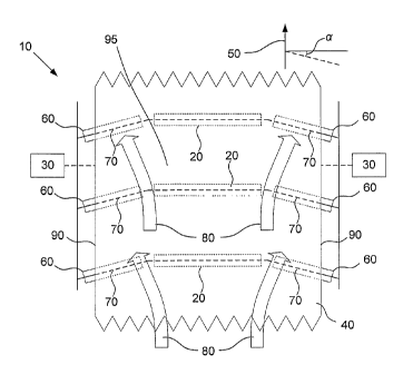
Referring to Figures 1 A and 1B there is provided an example of an apparatus
10 for
monitoring operation of a conveyor belt 40. In particular, the apparatus 10
includes a
CA 02716796 2010-08-13
WO 2009/092130 PC T/AU2009/000058
- 11 -
detection system 30 configured to detect transverse displacement of each edge
90 of a
portion of the conveyor belt 40 as the conveyor belt 40 travels past the
detection system 30,
and determine, using the transverse displacements of the edges 90 of the
conveyor belt 40
and one or more operating rules, if an operating irregularity of the conveyor
belt 40 has
occurred.
As the detection system 30 monitors a portion of the belt as it passes by the
detection
system, the entire belt can be monitored whilst not necessarily requiring
sensors or the like
along the entire length of the belt.
Additionally, as the transverse displacement of both edges are detected and
used in the
determination, a plurality of operating irregularities can be identified, such
as whether a
belt rip has occurred, whether unacceptable belt wander is occurring, and/or
whether one
or both edges of the belt have been damaged.
Continuing to refer to Figures 1A and 1B, the apparatus 10 can include a
plurality of
rollers 20. It will be appreciated that Figure 1A only illustrates a portion
of the conveyor
belt for clarity purposes only. The plurality of rollers 20 are configured to
support the
conveyor belt 40 moving in a transport direction as shown by arrow 50. The
plurality of
rollers 20 includes angularly offset rollers 60 having an axis 70 which is
angularly offset
relative to the transport direction 50, as represented by angle a, for
applying an outward
transverse force, as represented by arrow 80 in Figure 1A and arrow 85 in
Figure 1B
representing the transverse component of the force, toward opposing edges 90
of at least a
portion 95 of the conveyor belt 40.
As an outward transverse force 80 is applied across the width of the portion
of the
conveyor belt 40, effects of damage, such as rips or other flaws, of the belt
40 are
exacerbated thereby allowing the provision of a simple detection system to
detect an
operating irregularity in the belt 130.
An example of a section of a conveyor belt system modified to detect operating
CA 02716796 2010-08-13
WO 2009/092130 PCT/AU2009/000058
- 12 -
irregularities will now be described with reference to Figures 2A, 2B, 2C and
2D.
In particular, Figure 2A and 2B show an example of a section of an unmodified
conveyor
belt system. The section of the conveyor belt system 100 includes a support
frame 110 that
supports a number of idler rollers 120, 121. An endless conveyor belt 130 is
entrained
around the idler rollers 120, 121, as will be appreciated by persons skilled
in the art,
allowing the conveyor belt 130 to move over the rollers in the direction of
arrow 160.
It will be appreciated that in practice the conveyor belt system will
typically be of a greater
length, include an appropriate drive mechanism and a return path for the
conveyor belt. It
will therefore be appreciated that the section shown is for the purpose of
example only.
In this example, the idler rollers include centre idler rollers 120 arranged
substantially
horizontally, and outer idler rollers 121 can be inclined at an angle 0 to a
horizontal
support 165, such as the ground, so that the conveyor belt 130 is raised at
outer edges 131.
This is to ensure that material, shown generally at 140 remains confined to
the conveyor
belt 130 and does not fall there from.
As shown in Figure 2A, each of the idler rollers 120, 121 can be arranged with
their axes
perpendicular to the direction of travel 160 of the conveyor belt 130.
Referring to Figure 2C and 2D, there is shown the modified section of the
conveyor belt
system of Figures 2A and 2B. In particular, the section of the conveyor belt
system 200
includes a support frame 210 for supporting a number of idler rollers 220,
221, which in
turn support an endless conveyor belt 230, to allow movement of the conveyor
belt in the
direction of arrow 260, as will be appreciated by persons skilled in the art.
In contrast to the example of Figures 2A and 2B, in this example, the outer
rollers 221 are
arranged with their axes at an angle a to a direction perpendicular to the
direction of
motion 260 of the conveyor belt 230. As a result, as the conveyor belt 230
moves over the
idler rollers 221, this generates an outward lateral force that is applied to
the conveyor belt
CA 02716796 2010-08-13
WO 2009/092130 PCT/AU2009/000058
- 13 -
230, as shown by the arrows 261. This in turn provides a force extending
laterally across
the conveyor belt, in a direction perpendicular to the direction of motion
260, thereby
operating to move the conveyor belt in a width wise fashion. This operates to
exacerbate
the effect of any flaws, such as rips, of the belt width, as will be described
in more detail
below.
In order to further enhance the effect of the lateral force, it may be
desirable to adjust the
angle 0 at which the outer idler rollers 221 are provided with respect to the
horizontal or
ground 235. The reason for this is that having a steep angle 0 can reduce the
impact of the
lateral force, and in particular, reduce the increase in belt width that will
result from any
rips or other flaws. Accordingly, in one example, the angle 0 of the outer
idler rollers 221
with respect to the horizontal is also typically reduced as compared to the
configuration
shown in Figure 2B, as shown in Figure 2D. In one example, the outer idler
rollers 221
can be arranged horizontally, such that the angle 0 is 00, as shown in Figure
1B.
In order to further enhance the lateral force, the outer idler rollers 221 may
be rubber
lagged to increase the coefficient of friction between the belt and the idler
rollers.
The conveyor belt system is also modified to include two sensors positioned on
opposing
sides of the conveyor belt 230 as shown generally at 2501, 2502. Whilst two
sensors are
shown in this example, one sensor on each side of the belt, this is not
essential, and any
suitable number of sensors may be used. In this example, the sensors 2501,
2502 are
adapted to detect a distance between each sensor 2501, 2502 and a
corresponding edge 231
of the conveyor belt 230, as shown generally at SI, S2. The sensors 2501, 2502
then
typically provide an analogue output representing a scaled measurement equal
to the
distance between the sensor 2501, 2502 and the belt edge, although any
suitable form of
output can be used. The analogue output can be used to determine information
indicative
of the width W of the conveyor belt 230, which in turn allows a determination
of whether
an operating irregularity such as a belt rip, belt wander or edge damage to be
detected, as
will be described in more detail below.
CA 02716796 2010-08-13
WO 2009/092130 PCT/AU2009/000058
- 14 -
In one example, operating irregularity detection need only be performed in a
section of an
overall conveyor belt system, and accordingly, it will be appreciated that a
conveyor belt
system similar to that described above with respect to Figures 2A and 2B can
be
implemented, with a section of the overall belt system being modified or
retrofitted as
described above with respect to Figures 2C and 2D.
In another form, a plurality of sensor pairs may be positioned along the
length of the
conveyor belt. This arrangement can help assist early detection of an
operating irregularity
such as a belt rip, belt wander or edge damage as a full revolution of the
belt is not
required in order to detect an issue with the operation of the conveyor belt.
An example of a detection system will now be described with reference to
Figure 3.
In this example, the detection system is formed from a processing system 300
coupled to
each of the sensors 2501, 2502, with only a single sensor 250 being shown in
this example
for clarity purposes.
As shown, the sensor includes a transmitter 320 and a corresponding receiver
321. In use,
the processing system 300 controls the transmitter 320 causing it to emit
signals, such as
electromagnetic radiation, sound waves, ultrasound waves, or the like, as
shown by the
arrows 330. The signals are reflected from the conveyor belt edge 231, as
shown by the
arrows 331, with at least some of the reflected signals impinging on the
receiver 321, as
shown by the dotted line 332. An indication of the received signals are then
provided to
the processing system 300, allowing the processing system 300 to analyse the
received
indication, and determine the separation S.
The manner in which the separation is determined, will depend on the preferred
implementation and the nature of the signals. This could include, for example,
determining attenuation of the reflected signal, or more typically,
determining the time
taken for the signal to travel from the transmitter 320 to the receiver 321,
after reflection
from the conveyor belt edge 231.
CA 02716796 2010-08-13
WO 2009/092130 PCT/AU2009/000058
- 15 -
It will therefore be appreciated that the transmitter 320 and receiver 321
could be any form
of distance detection system, and that in some examples the transmitter and
receiver could
be formed from a single element capable of performing both tasks, and need not
be
separate elements per se. In one example, the transmitter 320 and the receiver
321 form an
ultrasonic system.
It will be appreciated from the above, that in use, the processing system 300
can be
configured to control the transmitter 320, receiving an indication of received
signals from
the receiver 321, and then using this information to determine the separation
S. The
separation S between each sensor and the respective belt edge can then be used
to
determine the transverse displacement of the belt.
Accordingly, any form of suitable processing system 300 may be used. In the
current
example, the processing system 300 includes at least a processor 310, a memory
311, an
input/output (I/O) device 312, such as a keyboard and display, and an external
interface
313, coupled together via a bus 314 as shown.
In use, the processor 310 executes instructions held in memory 311, allowing
the
transmitter 320 to be controlled, and to allow indications received from the
receiver 321 to
be interpreted. An indication of any determined results can then be presented
to an
operator using the I/O device 312.
Additionally and/or alternatively, the processing system 300 may be adapted to
control
operation of the conveyor belt system, for example to allow the conveyor belt
230 to be
stopped in the event that an operating irregularity is determined to have
occurred for the
conveyor belt such as a belt rip, unacceptable belt wander, edge damage or
other flaw is
detected. This can be achieved in any suitable manner, such as by coupling the
processing
system 300 to a conveyor belt drive system 360, via the external interface
313.
Accordingly, it will be appreciated that the processing system 300 may be
formed from
CA 02716796 2010-08-13
WO 2009/092130 PCT/AU2009/000058
- 16 -
any suitable processing system, such as a suitably programmed PC, or custom
configured
device, such as a micrologic controller, field programmable gate array (FPGA),
programmable logic controller (PLC), or the like.
An example of the method 400 in which the processing system 300 operates to
monitor the
operation of a conveyor belt will now be described with reference to Figure 4.
In this example, at step 401 the processing system 300 monitors the sensors
250 to detect
the transverse displacement of the conveyor belt associated with each sensor
2501, 2502.
At step 410 the transverse displacement of each edge of the belt, or one or
more variables
based thereon, are used with one or more operating rules to determine if an
operating
irregularity has occurred. The operating rules may include comparing a
threshold or other
value, to determine if an operating irregularity has occurred including a belt
rip, belt
wander or edge damage. At step 420 it is determined that the threshold is
exceeded, and if
not the process returns to step 401 to continue monitoring.
Otherwise, if it is determined that the threshold is exceeded at step 420 then
the process
moves on to step 430 with the processing system generating an alert.
Additionally and/or
alternatively, the conveyor belt may be stopped at step 440.
It will be appreciated that the comparison to the threshold may be performed
in any one of
a number of manners and this is influenced by the nature of conveyor belt
operating
irregularities, examples of which will now be described with reference to
Figures 5A and
5B.
In the example of Figure 5A, edge damage 500 has occurred on an edge 231 of
the
conveyor belt 230 as shown. This results in a reduction of the belt width from
a normal
belt width Wiv to a damaged belt width WR. It will be appreciated that this
similarly results
in a difference in separation S between the sensor 250 and the belt edge 231,
so that the
separation at the rip SR is greater than the separation in a normal or non-
damaged section of
CA 02716796 2010-08-13
WO 2009/092130 PCT/AU2009/000058
- 17 -
the belt 230, as shown at SN.
Accordingly, in this instance a damaged edge can be detected by determining if
a variable
indicative of the measured separation S is greater than that of a normal
separation SN.
Typically however, the exact position of the belt is subject to some natural
variation and it
is therefore necessary to define a threshold value slightly above the normal
separation SN to
avoid false positive indications of a damaged edge. In one example, the
threshold can be
set based on a percentage difference from the normal separation SN (eg: SN +
1%) although
any suitable value, such as a predetermined distance (eg: 1 cm) from the
normal separation
SN, or as manually selected value, can be used.
As an alternative to using the separation, the processing system 300 can use a
known
separation between the sensors 2501, 2502, together with the measured
separations SI, S2
to determine a variable indicative of the current belt width W. The current
belt width W
can then be compared to the normal belt width WN, or a threshold value based
or otherwise
derived therefrom, to again determine whether damage has occurred in a similar
manner.
In the example of Figure 5B, a rip 501 has occurred in the middle of the belt
230. If this
occurs in the conveyor belt system of Figure 2A, then with the idler rollers
120, 121
arranged perpendicularly to the direction of motion 160 of the conveyor belt
130, then in
general, the rip 501 would not have any impact on the belt width.
However, in the example of the apparatus of Figures 2C and 2D, the lateral
outward force
generated by the outer idler rollers 221 causes the belt to be moved in a
width wise
direction. This causes the rip 501 in the middle of the belt 230 to be opened
up, so that the
belt width in the rip region WR is greater than the normal width of the belt
i'VN.
It will be appreciated that this may therefore be used in a similar manner to
that described
above to allow a rip to be detected. However in this instance, a rip is
determined if one or
both of the measured separations SI, S2 are less than the normal separation
SN, or a
threshold value based or otherwise derived therefrom, or if the measured belt
width W is
CA 02716796 2010-08-13
WO 2009/092130 PCT/AU2009/000058
- 18 -
greater than the normal belt width WN or a threshold based on or derived
therefrom, then
damage is again determined.
It will therefore be appreciated that during the comparisons at step 420, the
comparison
may be performed either based on one or both of the separations SI, S2, and/or
on the
overall belt width W. Furthermore, the comparison typically involves comparing
these
values to both upper and lower threshold values to allow detection of both of
the types of
rips shown in Figures 5A and 5B. Thus, variables such as the separations SI,
S2 and/or the
belt width W can be compared to threshold values, so that the threshold is
exceeded if the
variable is below a lower threshold value or above an upper threshold value.
Referring to Figure 5C there is shown an example of detecting an operating
irregularity of
belt wander for belt 500. In particular, Figure 5C shows the belt has moved to
the left by
distance DBW due to the conveyor belt suffering some degree of belt wander.
The dotted
line in Figure 5C shows the reference position of the conveyor belt. In this
instance, the
transverse displacement S1 and S2 for each edge is measured via sensors 250
and 251.
Accordingly, in this instance, unacceptable belt wander can be detected by
determining
that both edges have incurred a transverse displacement and that the measured
distance for
one sensor has increased and that the other measured distance has decreased
for the other
sensor. Once these characteristics have been identified, the smaller distance
is subtracted
from the larger distance to determine a measured belt wander distance. The
measured belt
wander distance is then compared against a normal amount of belt wander
distance. If the
measured belt wander distance exceeds the normal amount of belt wander, then
an
operating irregularity of belt wander has been identified. As also discussed
above, a
percentage difference from the normal belt wander distance may be used to
determine if an
operating irregularity has occurred.
It will therefore be appreciated that the above described process operates by
moving the
conveyor belt in a width wise direction, and then measuring a variable
indicative of the
resulting belt width. This allows the processing system 300 to determine if
there is any
CA 02716796 2010-08-13
WO 2009/092130 PCT/AU2009/000058
- 19 -
deviation between the measured variable and an expected value. This, in turn,
allows the
processing system 300 to determine if it is likely that the belt is damaged
and then take
appropriate action.
The nature of any action taken may vary depending on the preferred
implementation. Thus,
in one example, an alert can be generated, allowing the belt to be inspected
manually, to
allow assessment of whether the conveyor belt needs to be repaired or
replaced.
Alternatively, the conveyor belt can simply be stopped to prevent further
damage.
In one example, the processing system 300 may make an assessment as to whether
to
generate an alert, or stop the belt, based on the results of the comparison.
Thus, for
example, two upper and lower threshold values could be defined. In this
instance, if only
the first threshold value is exceeded, then this indicates that whilst damage
is present, this
is currently only minor, and hence the conveyor belt can continue operating,
so only an
alert is generated. However, if the second threshold value is also exceeded,
representing a
greater deviation from the expected normal belt width WN being exceeded, then
this could
indicate a more serious damage or tracking has been detected, and the conveyor
belt could
be shut down so immediate corrective action could be taken.
However, typically the processing system 300 will operate to stop the conveyor
belt in the
event that any operating irregularity is detected, thereby allowing an
operator to manually
assess what action should be taken.
Thus, as will be appreciated by persons skilled in the art, the processing
system can be
adapted to not only determine the presence of an operating irregularity, but
also to assess
the magnitude and hence severity of the damage, and thereby take appropriate
action.
In one example, the measuring procedure can be performed along a section of
the conveyor
belt system so that the entire length of the conveyor belt is monitored as it
passes through
this section.
CA 02716796 2010-08-13
WO 2009/092130 PCT/AU2009/000058
- 20 -
In general, in the event that damage is present, the effect of moving the belt
in a lateral
width wise direction could exacerbate the severity of rip, and this could
result in a loss of
any material thereon. Thus, for example, material can fall through the rip in
the belt and
land on the return side of the conveyor belt path. A further issue is that the
weight of any
material on the belt, could impact on the measurement process.
Accordingly, in one example, the rip detection is performed on a section of
the conveyor
belt system where material 140 is not present on the conveyor belt 230. Thus,
this could
be performed by positioning the lateral force generating idler rollers either
after the
immediate transfer on the carry side of the belt, or behind the transfer on
the return side of
the belt.
However, this is not essential, and in some examples, it may be preferred to
perform the
monitoring in a region of the conveyor belt where material is present. An
example of this
will now be described with reference to Figures 8A and 8B.
In this example, a return belt path is also shown. Accordingly, the conveyor
belt system
includes idler rollers 220, 221 for supporting the conveyor belt 230, to allow
transport of
material 140 in the direction of arrow 160, as described above. The conveyor
belt 230
passes around a drive roller 800, and is then supported by return path idler
rollers 820, with
the conveyor belt on the return path being indicated by the reference numeral
830.
In this example, should a rip occur in the conveyor belt 230, then this can
allow material
140 to fall through the conveyor belt 230, as shown by the arrow 850, thereby
resulting in
material 840 being transported along the return path in a direction opposite
to that of the
arrow 160.
Detectors can be provided for sensing material on the return belt path, which
can be
indicative of a belt rip. In one example, this is achieved by having a member,
or other
sensor, extend across the conveyor belt return path, as shown at 850, so that
the presence
of any material can be detected. Thus, for example, an optical sensing system
can be used,
CA 02716796 2010-08-13
WO 2009/092130 PCT/AU2009/000058
- 21 -
in which a radiation source, such as a laser sensor, generates a beam of light
that extends
across the return path to impinge on a corresponding sensor. Alternatively, a
physical
member, such as a piece of wire or the like, can extend across the return path
at 850, with
the wire being disturbed or broken should material impinge thereon, thereby
allowing the
presence of material 840 to be determined.
In any event, in such systems, if material is detected on the return path
conveyor belt 830,
this is indicative of a belt rip or spillage in the conveyor belt 230, and
this can therefore be
used to stop the conveyor or generate an alert, in a manner similar to that
described above.
Thus, for example, any detection system can be coupled to the processing
system 300,
allowing the processing system 300 to receive signals from the detection
system and
determine from the signals if material is present on the belt return path. In
this instance the
processing system can then stop the conveyor or generate an alert as required.
In a
preferable form, the detection system is a radiation source, such as a laser
beam wherein
when laser beam's path is broken by material, an operating irregularity has
been detected.
Still referring to Figure 8A, a detector in the form of a sensor, such as a
laser sensor 870,
may be configured to sense if material upon the conveyor belt is equal to or
above a
maximum height considered acceptable for the particular conveyor belt. In
particular, the
laser sensor 870 emits a laser beam 875 which if broken by material is
detected by the laser
sensor is determined by the detection system as being indicative of an
operational
irregularity. Whilst the laser sensor 870 is shown located at one end of the
conveyor belt,
this is merely shown for clarity purposes and thus the laser sensor 870 can be
directed
across the width of the conveyor belt. Additionally, as discussed above, the
maximum
height detector can be provided in the form of other forms of sensors such as
a physical
member like a wire or the like.
It will be appreciated that in the above described examples, in which the belt
is urged apart
as shown by the arrows 261 in Figure 2C, then this causes an increase in the
effective size
of any rip, which in turn can lead to an increase in any material falling
through the
conveyor belt 230 and onto the conveyor belt 830 on the return path. From
this, it will be
CA 02716796 2014-10-02
. .
- 22 -
appreciated that the use of idler rollers 221 to spread the conveyor belt 230
in a lateral
direction can also increase the effectiveness of existing belt management
detection systems,
which therefore may be used in addition or alternatively, to the belt rip
sensors 250.
It will be appreciated by persons skilled in the art, that the use of angled
idler rollers 221,
which operate to urge the conveyor belt in a lateral direction can therefore
additionally, or
alternatively be used with any belt monitoring detection system that is
capable of detecting
material on the conveyor belt return path.
It will also be appreciated from the above that a range of different
procedures could be
performed by the processing system 300 in order to detect defects in the
operation of the
conveyor belt, and an example of an alternative belt monitoring process 600
will now be
described with reference to Figure 6.
In this example, a configuration phase is used to determine a belt width
profile along the
length of the belt. This is performed when it is known that the conveyor belt
is either
undamaged, or at least operating in accordance with acceptable parameters.
Thus, the belt
may include minor edge rips which are not material to the operation of the
conveyor belt
system, in which case even though damage exists, it may therefore be desirable
to continue
operation of conveyor belt system.
To generate the profile, at step 601, the processing system 300 monitors the
sensors 250 to
determine a start point. The start point represents a fixed point on the belt
from which the
profile is measured, and may be indicated by an appropriate indicator on the
conveyor belt
230, such as a designated protrusion or depression of a set length, or by any
other
appropriate mechanism, which can preferably be detected using the sensor 250.
In another
form, the start point may be a radio-frequency identification (RFID) tag which
is installed
in or upon the conveyor belt which can be sensed to indicate a revolution of
the conveyor
belt.
At step 610 the processing system 300 monitors the sensors 250 to determine
how the
separations Si, Sz, or one or more variables based thereon, such as the belt
width, change
CA 02716796 2010-08-13
WO 2009/092130 PCT/AU2009/000058
- 23 -
as the conveyor belt moves passed the sensors 250. This process may be
continuous, or
may involve periodic measurements as will be appreciated by persons skilled in
the art.
The process is continued until the processing system 300 detects the start
point, indicating
that an entire revolution of the conveyor belt has been completed. At this
point the
separation measurements SI, S2, or other derived variable such as the belt
width W, can be
used to generate a belt profile at step 620.
By performing this configuration process when it is known that the conveyor
belt is in an
acceptable working condition, then this allows an acceptable profile of the
separations Sh
52, or the belt width W, to be generated at step 620. In one form, a newly
installed belt
may be monitored during this configuration process in order to determine a
belt profile.
Once the profile has been generated, this allows monitoring to be performed so
that
deviations from the profile can be used to assess whether an operating
irregularity has
occurred. At this point, the configuration process has completed, as indicated
by the
broken arrow between steps 620 and 630.
In a variation, the start position can be used to determine if an operating
irregularity has
occurred as described in relation to steps 630 onwards.
At step 630 the processing system 300 monitors the sensor to determine the
start point and
then monitors the sensors 250 at step 640 to determine the belt sensor
separations SI, 82.
The start point is determined such that the measured values from the sensors
are compared
against the corresponding measurements of the profile. This information, or a
variable
based thereon, such as the belt width W is then compared to the generated
profile, at step
650.
At step 660 it is determined if the current measured separations SI, 52 or
width W differ
from the profile by more than a predetermined amount, which may for example be
defined
as a threshold. As in the previous example, both upper and lower thresholds
may be
CA 02716796 2010-08-13
WO 2009/092130 PCT/AU2009/000058
- 24 -
defined to ensure both of the irregularity types described above can be
detected. If not, the
process returns to step 640 to allow monitoring to continue.
However, if it is determined that the difference exceeds the threshold, then
at step 670 an
alert is generated, and/or the conveyor belt can be stopped at step 680, in a
manner similar
to that described above.
Accordingly, in this example, a profile is generated for a particular conveyor
belt, with
comparisons then being performed with respect to this profile, thereby
allowing variations
in belt width over time to be easily detected. This in turn allows for the
easy and accurate
detection of an operation defect which can in turn lead to early system
failure detection. It
will be appreciated that this profile is specific to the respective conveyor
belt system and
accordingly, a profile would need to be developed for each conveyor belt
system.
However, by developing a profile specific to the conveyor belt, this takes
into account an
acceptable belt configuration and is therefore less prone to error, as may
occur for example
due to natural variations in belt width.
From this, it will be appreciated that the processing system 300 may include a
range of
configurable parameters that can be used in different belt damage detection
processes, and
these can include any one or more of:
a maximum belt width;
a minimum belt width;
a belt length, which can be used for 'average belt width' calculation; and,
a belt velocity, which can be used for 'average belt width' calculation.
Other parameters may also be stored as will be appreciated by persons skilled
in the art.
This allows the processing system to determine a number of parameters relating
to
operation of the conveyor belt system including:
a belt width;
belt tracking; and,
an 'average belt width'.
CA 02716796 2010-08-13
WO 2009/092130 PCT/AU2009/000058
-25 -
In a variation, multiple sets of parameters may be stored by the processing
system, wherein
each set of parameters can be used for comparison depending upon the weight of
material
which the belt, or a portion thereof, is supporting. In one form, a first set
of parameters
may be generated when no weight is supported upon the conveyor belt, and then
a second
set of parameters may be generated when a particular weight of material is
support upon
the conveyor belt, or a portion thereof. When the conveyor belt is operating,
one of the set
of parameters can be used for determining if an operating irregularity has
been detected
based upon the weight of material which is being supported. In one example,
the user may
select the appropriate set of parameters to be used by using an input device
of the
processing system, such as a keyboard, mouse or the like, to indicate the set
of parameters
for use according to the weight of material supported on the belt. However, in
an additional
or alternate form, the apparatus may include one or more weight sensors 890
coupled to
the processing system which senses the amount of weight supported by the belt,
or portion
thereof The processing system uses the sensed weight to automatically select
the
applicable set of parameters according to the sensed weight.
In the above described examples, the outer idler rollers 221 are provided at
an angle ct to a
direction perpendicular to the direction of motion of the conveyor belt 230.
This is
performed to move the belt in a width wise direction and exacerbate the effect
of any
damage It will be appreciated that in some circumstances it may be desirable
to adjust the
magnitude of the force applied to a system to ensure movement.
It will be appreciated that the processing system 300 may also perform
additional
functionality. For example, by comparing differences between the current
measured
separations Sj, S2 the processing system 300 can determine tracking for the
belt, and this
may additionally be used to generate an alert or stop the conveyor belt in the
event that the
belt is not tracking correctly.
The processing system 300 can also store a record of any measurements made,
such as any
current measured separations Sh 82 allowing these to be subsequently
retrieved. In this
CA 02716796 2010-08-13
WO 2009/092130 PCT/AU2009/000058
- 26 -
regard, by having the processing system 300 also store an indication of when
the
measurement was made, such as a time and date stamp, this allows the
measurements to be
subsequently reviewed, which can be useful for identifying events that
contribute towards
operating irregularities.
Thus, for .example, certain events, such as activation of a feed chute, could
cause changes
in belt width as material is added to the belt. In this instance, repeated
activation of the
chute could ultimately contribute to belt damage. However, by reviewing the
changes in
belt width that occur when the chute is activated, this can allow operators to
assess the
impact of this event, and determine if changes are required, for example in
the activation
process.
Adjustment of the lateral force applied to the belt can be adjusted by
controlling the angle
a and an example of a system for achieving this will now be described with
reference to
Figures 7A to 7C.
In this example, a frame member 700 has a connector 710 movably mounted
thereon to
allow the connector 710 to be moved to any position along the frame member
700. The
connector 710 can be held in a desired position using any appropriate locking
means. The
idler roller 221 is supported by an axle 730 having a first end mounted to the
connector
710 and a second end mounted to a support 740. The mountings to the connector
710 and
the support 740 are arranged to allow the angle at which the axle extends from
the
connector 710 and the support 740 to vary as required. In addition to this,
the axle 730 can
be formed from first and second axle portions 731, 732 which cooperate to
provide a
telescopic arrangement, allowing adjustment of the axle length.
In use, this allows the connecting member 710 to be moved along the frame
member 700
as shown in Figure 7B. The axle mountings allow the axle to remain attached to
the
connector 710 and the support 740. With the support 740 remaining stationary,
the angle a
is adjusted, thereby varying the magnitude of the lateral force that will be
applied to the
conveyor belt 230, as will be appreciated by those skilled in the art.
CA 02716796 2010-08-13
WO 2009/092130 PCT/AU2009/000058
- 27 -
In one variation, the nature of the connector 710 and the axle mountings can
vary
depending on the preferred implementation. In one example, the connector is as
shown in
Figure 7C. In this example, the connector 710 includes a first aperture for
receiving the
frame member 700, to allow relative movement of the connector 710 along the
frame
member 700. A second aperture 712 is provided for receiving a locking means,
such as a
thumbscrew 720, which can be urged against the frame member 700, to thereby
hold the
connector 710 stationary relative to the frame member 700.
A socket 713 is also provided which can cooperate with a ball provided on the
first axle
portion 731 to provide a ball and socket connection, which allows relative
movement of
the axle 730 with respect to the connector 710. It will be appreciated that
the second axle
portion 732 can be coupled to the support 740 using a similar arrangement.
It will also be appreciated that in situations where it is desirable to adjust
the angle of the
idler rollers 221 with respect to the horizontal or ground 265, this can be
achieved in a
similar manner, or by allowing adjustment of a height of the frame member 700
relative to
the ground 265 in the arrangement of Figures 7A to 7C.
It will be appreciated that the above described system therefore utilises belt
width sensing
to thereby allow for accurate and reliable belt damage detection.
In particular, the system is capable of detecting rips where the conveyor belt
is ripped in a
lengthwise direction, but the full belt is still conveyed along, as well as
when an edge of
the belt is cut and the belt width reduced.
In the first instance, idler rollers are configured to apply a lateral force
to the belt and
therefore draw the belt apart in the event that damage occurs. This results in
a
corresponding change in belt width, which can then be detected using suitable
belt width
sensing. Similarly, in the event of an edge rip, the belt width sensing can
also detect the
associated change in belt width.
CA 02716796 2013-12-17
- 28 -
In practice, the sensing may be performed when material is not present on the
conveyor
belt, and this is therefore typically achieved by positioning the lateral
force generating idler
rollers either after the immediate transfer on the carry side of the belt, or
behind the
transfer on the return side of the belt.
Alternatively, it may be desirable to perform sensing when material is present
on the
conveyor belt, so that this can be used to allow detection systems that detect
material on
the return belt path to function more effectively.
The unit utilises remote distance sensing systems, which therefore do not need
to
physically contact the belt, thereby reducing the likelihood of failure.
Furthermore the
system does not require any antennae to be embedded in the belt, thereby
removing the
need to custom and expensive conveyor belts. The system also will check the
entire length
of belt and not just set lengths as some other systems do.
It will be appreciated that the system therefore provides a simple and robust
technique for
detecting belt damage, thereby resulting in an easily maintainable device that
can be
understood and serviced by site personnel and not require the need for
specialized people
to maintain.
The system will also work on any belt or construction, and does not require a
specific
configuration of conveyor belt, such as a belt incorporating antennae, is
used.
Persons skilled in the art will appreciate that numerous variations and
modifications will
become apparent. All such variations and modifications which become apparent
to
persons skilled in the art, should be considered to fall within the scope that
the invention
broadly appearing before described.