Note: Descriptions are shown in the official language in which they were submitted.
CA 02717062 2015-02-20
1
MACHINERY ARRANGEMENT FOR MARINE VESSEL
Technical field
The invention relates to a machinery arrangement for a marine vessel, which
machinery arrangement comprises a combustion unit, an exhaust gas duct
assembly, which includes a first branch pipe and a second branch pipe and is
connected to the combustion unit for receiving an exhaust gas flow and for
leading
the exhaust gas flow to the atmosphere, and an exhaust gas cleaning system
arranged in a flow direction of the exhaust gas, whereby the second branch
pipe is
connected to the combustion unit and the first branch pipe is connected to the
second branch pipe. The present invention also relates to a method for
operating a
machinery arrangement of a marine vessel.
Background art
Machinery arrangements for marine vessels conventionally comprise one or more
combustion units, such as diesel engines, oil-fired boilers, incinerators,
etc. The
combustion units usually have independent exhaust gas duct assemblies, whereby
also the cleaning of exhaust gases takes place separately for each combustion
unit.
Gases coming from oil-fired boilers are sometimes referred to as flue gases.
Gases
from diesel engines are mostly called exhaust gases. In the following the
general
term exhaust gas will be used with regard to gases from all relevant types of
combustion units.
Reduction of exhaust gas emissions can be obtained by improving the
performance
of the combustion units, by using cleaner fuel, or by cleaning the exhaust
gases.
CA 02717062 2015-02-20
' 2
In previously known solutions, with regard to cleaning the exhaust gases,
machinery
arrangements have been provided with exhaust gas cleaning systems for nitric
oxides (N0x). Presently, however, due to increasing demands to reduce exhaust
gas emissions, especially in port conditions and near the coast, there will be
a need
to clean sulphuric oxides (S0x) emanating from sulphur rich fuels, such as
conventional heavy fuel oil.
Generally speaking, exhaust gas cleaning systems cause flow resistance in the
exhaust gas duct assembly, which is undesirable in view of the efficiency of
the
exhaust gas cleaning and the operation of the combustion units.
Summary of the invention
Certain exemplary embodiments can provide a machinery arrangement for a marine
vessel, which machinery arrangement comprises a combustion unit, an exhaust
gas
duct assembly, which includes a first branch pipe and a second branch pipe and
is
connected to the combustion unit for receiving an exhaust gas flow and for
leading
the exhaust gas flow to the atmosphere, and an exhaust gas cleaning system
arranged in a flow direction of the exhaust gas, whereby the second branch
pipe is
connected to the combustion unit and the first branch pipe is connected to the
second branch pipe, wherein the first branch pipe is arranged to lead the
exhaust
gas flow to the exhaust gas cleaning system and further to the atmosphere, a
fan
unit is provided in flow connection with the first branch pipe, a first valve
means is
provided in the first branch pipe, and in that the second branch pipe is
arranged to
function as a stand-by exhaust pipe.
Certain exemplary embodiments can provide a method for operating a machinery
arrangement of a marine vessel, in which method an exhaust gas flow from a
combustion unit is led to an exhaust gas cleaning system through an exhaust
gas
duct assembly, which includes a first branch pipe and a second branch pipe,
CA 02717062 2015-02-20
2a
whereby the second branch pipe is connected to the combustion unit and the
first
branch pipe is connected to the second branch pipe, and in which method the
exhaust gas flow is led to the atmosphere, wherein the exhaust gas flow is led
to
the exhaust gas cleaning system through the first branch pipe, that the
exhaust gas
flow is controlled by a fan unit deployed in flow connection with the first
branch pipe
and by a first valve means deployed in the first branch pipe, and in that the
second
branch pipe is deployed as a stand-by exhaust pipe.
The basic idea of the invention is to avoid increased exhaust gas back
pressure
caused by cleaning devices, to reduce equipment for cleaning exhaust gases and
to
optimize cleaning performance in relation to the degree of operation of the
combustion units. Firstly, the exhaust gas duct assembly is divided into a
first
branch pipe leading to the exhaust gas cleaning system and into a second
branch
pipe connected to and extending from the combustion unit, also leading to the
atmosphere. Secondly, a fan unit is provided in flow connection with the first
branch
pipe and a first valve means is provided in the first branch pipe.
Advantageously the
exhaust gas from a number of combustion units connecting to corresponding
first
branch pipes and second branch pipes is cleaned by the same exhaust gas
cleaning system.
In normal sea-going conditions, when the combustion units are driven at a
given
level with a given exhaust gas flow, the exhaust gas cleaning system may have
a
design performance for the corresponding combined load of the combustion
units.
Consequently, in port conditions or near the coast, when the combustion units
normally are driven at a level far below said level for normal sea-going
conditions
and the exhaust gas flow is considerably smaller, the exhaust gas cleaning
system
will provide a higher cleaning performance corresponding to stricter
requirements
typical for port conditions and corresponding areas near the coast.
CA 02717062 2010-08-26
WO 2009/125052 PCT/F12009/050193
3
In order to be in flow connection with the first branch pipe, the fan unit can
ad-
vantageously be arranged between the first branch pipe and the exhaust gas
cleaning system. Alternatively, the fan unit can be arranged after the exhaust
gas cleaning system in the flow direction of the exhaust gas. Yet another
advan-
tageous arrangement is to arrange the fan unit in the first branch pipe.
The first branch pipe is advantageously provided with a first valve means for
regulating or closing off of the exhaust gas flow, and a possible air flow, in
the
first branch pipe.
In a machinery arrangement which comprises a number of combustion units,
each of the combustion units is advantageously connected to corresponding
first branch pipes and second branch pipes respectively.
In this case, the various first branch pipes are advantageously connected to a
common collecting branch, which is connected to the exhaust gas cleaning sys-
tem.
As one alternative, the fan unit is advantageously arranged in the common col-
lecting branch.
The exhaust gas cleaning systems advantageously comprises a cleaning de-
vice for sulphuric oxides (S0x). Said device advantageously comprises a scrub-
ber unit provided with an exhaust gas pipe.
In a marine vessel where the combustion unit is arranged in an engine room,
the engine room preferably comprises an engine room casing with an engine
room ventilation outlet leading to an enclosure outside a funnel portion of
the
engine room casing.
In a marine vessel where the exhaust gas cleaning system comprises a scrub-
ber unit with an exhaust gas pipe, the exhaust gas pipe is advantageously ar-
ranged in the enclosure. The scrubber unit is advantageously arranged outside
the enclosure. This enhances the treatment of the exhaust gas discharge from
the exhaust pipe.
CA 02717062 2015-02-20
4
By also arranging the first branch pipe in the enclosure, the treatment of the
exhaust
gas can be made yet more efficient.
In addition, it is advantageous that the enclosure is open-ended and is
provided with
a jacket portion surrounding at least part of the exhaust gas pipe.
Brief description of drawings
In the following the invention will be described, by way of example only, with
reference to the accompanying schematic drawing, in which
Figure 1 illustrates a first embodiment of the present invention,
Figure 2 illustrates a second embodiment of the present invention,
Figure 3 illustrates a third embodiment of the present invention.
Figure 4 illustrates a fourth embodiment of the present invention, and
Figure 5 illustrates a fifth embodiment of the present invention.
Detailed description
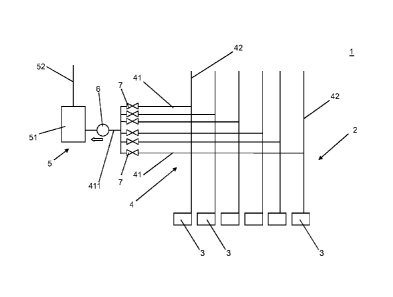
In Figure 1 a machinery arrangement for a marine vessel 1 is generally
indicated by
reference sign 2. The machinery arrangement comprises a combustion unit 3, in
this embodiment a number of combustion units. The combustion units may include
diesel engines, oil-fired boilers, incinerators, etc.
Further, the machinery arrangement 2 comprises an exhaust duct assembly 4
for receiving an exhaust gas flow from the combustion units and for leading
the
exhaust gas flow to the atmosphere. The exhaust gases are treated by an
exhaust gas cleaning system 5 arranged in the flow direction (main intended
flow
CA 02717062 2010-08-26
WO 2009/125052 PCT/F12009/050193
direction of the exhaust gas is indicated by a block arrow) of the exhaust
gas.
The exhaust gas cleaning system includes a cleaning device for sulphuric ox-
ides (S0x), e.g. a scrubber unit 51, which is provided with an exhaust gas
pipe
52.
5 The exhaust gas duct assembly 4 includes a first branch pipe 41 leading
to the
exhaust gas cleaning system 5 and a second branch pipe 42 connected to and
extending from the combustion unit 3, also leading to the atmosphere. An ex-
haust gas flow from the combustion unit 3 is firstly led into the second
branch
pipe 42 and further to the atmosphere, or alternatively from the second branch
pipe 42 to the first branch pipe 41, through the exhaust gas cleaning system
5,
and further to the atmosphere. This is discussed more in detail below.
In this embodiment, which includes a number of combustion units, each com-
bustion unit 3 is connected to a first branch pipe 41 through a second branch
pipe 42 respectively. A fan unit 6 is provided in flow connection with the
first
branch pipe 41 relating to each combustion unit 3. In this embodiment the fan
unit 6 is arranged between the first branch pipes 41 and the exhaust gas clean-
ing system 5, in a common collecting branch 411, which connects the various
first branch pipes and the scrubber unit 51.
Each of the first branch pipes 41 is provided with a first valve means 7,
which
advantageously is arranged to function as a shut-off valve and flow control
valve.
In the following the operation of the machinery arrangement according to the
invention shall shortly be described.
In operation, as one or more combustion units 3 are driven, exhaust gas is gen-
erated and is led into the exhaust gas duct assembly 4. The purpose is to draw
substantially all of the exhaust gas by the fan unit 6 through the first
branch
pipes 41 and to push the exhaust gas via the common collecting branch 411
into the scrubber unit 51 in order to clean the same. The second branch pipes
42 basically function as stand-by exhaust pipe for the respective combustion
CA 02717062 2010-08-26
WO 2009/125052 PCT/F12009/050193
6
units 3, preferably so that a minimum of fresh air is provided to the scrubber
unit
51 in order to prevent escape of un-cleaned exhaust gases.
The fan unit 6 is advantageously equipped with a frequency converter and/or
guide vanes for flexible control of its appropriate function in relation to
the drive
mode of the respective combustion units 3. Back-flow of exhaust gas from the
common collecting branch 411 to other combustion units is controlled by the
first valve means 7 provided in each first branch pipe 41. The first valve
means
7 are arranged to balance the flow in the active first branch pipes 41, i.e.
the
first branch pipes connected to a driven combustion unit 3. On the other hand,
the first valve means 7 are also arranged to shut-off the flow in the inactive
first
branch pipes 41, i.e. the first branch pipes connected to a non-operational
com-
bustion unit 3.
This arrangement also ensures that the exhaust gas back pressure, with regard
to each combustion unit 3, remains about the same or slightly lower than in a
conventional machinery installation.
In case e.g. of malfunction of the scrubber unit 51, the first valve means 7
can
be used to prevent the flow of hot exhaust gases to the scrubber unit. In a
situa-
tion like this, the exhaust gases can be led directly through the second
branch
pipes 42 to the atmosphere, whereby exhaust gas emission control may be
achieved by using fuel with lower sulphur content.
Each of the second branch pipes 42 is advantageously provided with a second
valve means (not shown), a temperature sensor (not shown) and a flow sensor
(not shown).
The temperature sensors in the second branch pipes 42 can be used to control
that there is no inadvertent flow of hot, un-cleaned exhaust gases into the at-
mosphere. The flow sensors in the second branch pipes 42 can correspondingly
be used to control the flow of fresh air, i.e. said minimum of fresh air
discussed
above, provided to the scrubber unit 51. The second valve means may regulate
the flow as such in the second branch pipes.
CA 02717062 2010-08-26
WO 2009/125052 PCT/F12009/050193
7
For optimizing the overall operation of the exhaust gas cleaning system the
fan
unit 6, the first valve means 7, and also as appropriate the second valve
means,
the temperature sensor and the flow sensor, are connected to a central control
unit (not shown) for monitoring the exhaust gas flow.
In conclusion, such a central control unit provides the means to ensure that a
minimum of fresh air continuously can be sucked backwards from the active
second branch pipes, that the air flow to and therefore the exhaust gas load
(combined air and exhaust gas flow) to the scrubber unit is minimised, and
that
power consumption can be optimised. Furthermore, by minimizing the flow of
cold air from the second branch pipes, any risk for condensation of sulphuric
acid at the point of mixing of said cold air and hot exhaust gases can be
avoided.
The deployment of the central control unit remains within the knowledge of a
person skilled in the art, and is therefore not discussed in more detail in
this
connection.
In Figure 2 a machinery arrangement for a marine vessel 1 is generally indi-
cated by reference sign 2. The machinery arrangement comprises a combustion
unit 3, in this embodiment a number of combustion units. The combustion units
may include diesel engines, oil-fired boilers, incinerators, etc.
Further, the machinery arrangement 2 comprises an exhaust duct assembly 4
for receiving an exhaust gas flow from the combustion units and for leading
the
exhaust gas flow to the atmosphere. The exhaust gases are treated by an ex-
haust gas cleaning system 5 arranged in the flow direction (main intended flow
direction of the exhaust gas is indicated by a block arrow) of the exhaust
gas.
The exhaust gas cleaning system includes a cleaning device for sulphuric ox-
ides (S0x), e.g. a scrubber unit 51, which is provided with an exhaust gas
pipe
52.
The exhaust gas duct assembly 4 includes a first branch pipe 41 leading to the
exhaust gas cleaning system 5 and a second branch pipe 42 connected to and
extending from the combustion unit 3, also leading to the atmosphere. An ex-
CA 02717062 2010-08-26
WO 2009/125052 PCT/F12009/050193
8
haust gas flow from the combustion unit 3 is firstly led into the second
branch
pipe 42 and further to the atmosphere, or alternatively from the second branch
pipe 42 to the first branch pipe 41, through the exhaust gas cleaning system
5,
and further to the atmosphere. This is discussed more in detail below.
In this embodiment, which includes a number of combustion units, each com-
bustion unit 3 is connected to a first branch pipe 41 and a second branch pipe
42 respectively. The first branch pipes 41 converge in a common collecting
branch 411, which connects the various first branch pipes and the scrubber
unit
51.
A fan unit 6 is provided in flow connection with the first branch pipe 41 of
each
combustion unit 3. The fan unit 6 is arranged after the exhaust gas cleaning
system 5 in the flow direction (block arrow) of the exhaust gas, in this
embodi-
ment in the exhaust gas pipe 52 of the scrubber unit 51.
Each of the first branch pipes 41 is provided with a first valve means 7,
which
advantageously is arranged to function as a shut-off valve and flow control
valve.
In the following the operation of the machinery arrangement according to the
invention shall shortly be described.
In operation, as one or more combustion units 3 are driven, exhaust gas is gen-
erated and is led into the exhaust gas duct assembly 4. The purpose is to draw
substantially all of the exhaust gas by the fan unit 6 through the first
branch
pipes 41 and via the common collecting branch 411 through the scrubber unit
51 in order to clean the same. The second branch pipes 42 basically function
as
stand-by exhaust pipe for the respective combustion units 3, preferably so
that
a minimum of fresh air is provided to the scrubber unit 51 in order to prevent
escape of un-cleaned exhaust gases.
The fan unit 6 is advantageously equipped with a frequency converter and/or
guide vanes for flexible control of its appropriate function in relation to
the drive
mode of the respective combustion units 3. Back-flow of exhaust gas from the
common collecting branch 411 to other combustion units is controlled by the
CA 02717062 2010-08-26
WO 2009/125052 PCT/F12009/050193
9
first valve means 7 provided in each first branch pipe 41. The first valve
means
7 are arranged to balance the flow in the active first branch pipes 41, i.e.
the
first branch pipes connected to a driven combustion unit 3. On the other hand,
the first valve means 7 are also arranged to shut-off the flow in the inactive
first
branch pipes 41, i.e. the first branch pipes connected to a non-operational
com-
bustion unit 3.
This arrangement also ensures that the exhaust gas back pressure, with regard
to each combustion unit 3, remains about the same or slightly lower than in a
conventional machinery installation.
In case e.g. of malfunction of the scrubber unit 51, the first valve means 7
can
be used to prevent the flow of hot exhaust gases to the scrubber unit. In a
situa-
tion like this, the exhaust gases can be led directly through the second
branch
pipes 42 to the atmosphere, whereby exhaust gas emission control may be
achieved by using fuel with lower sulphur content.
Each of the second branch pipes 42 are advantageously provided with a sec-
ond valve means (not shown), a temperature sensor (not shown) and a flow
sensor (not shown).
The temperature sensors in the second branch pipes 42 can be used to control
that there is no inadvertent flow of hot, un-cleaned exhaust gases into the at-
mosphere. The flow sensors in the second branch pipes 42 can correspondingly
be used to control the flow of fresh air, i.e. said minimum of fresh air
discussed
above, provided to the scrubber unit 51. The second valve means may regulate
the flow as such in the second branch pipes.
For optimizing the overall operation of the exhaust gas cleaning system the
fan
unit 6, the first valve means 7, and also as appropriate the second valve
means,
the temperature sensor and the flow sensor, are connected to a central control
unit (not shown) for monitoring the exhaust gas flow.
In conclusion, such a central control unit provides the means to ensure that a
minimum of fresh air continuously can be sucked backwards from the active
second branch pipes, that the air flow to and therefore the exhaust gas load
CA 02717062 2010-08-26
WO 2009/125052 PCT/F12009/050193
(combined air and exhaust gas flow) to the scrubber unit is minimised, and
that
power consumption can be optimised. Furthermore, by minimizing the flow of
cold air from the second branch pipes, any risk for condensation of sulphuric
acid at the point of mixing of said cold air and hot exhaust gases can be
5 avoided.
The deployment of the central control unit remains within the knowledge of a
person skilled in the art, and is therefore not discussed in more detail in
this
connection.
In Figure 3 a machinery arrangement for a marine vessel 1 is generally indi-
10 cated by reference sign 2. The machinery arrangement comprises a
combustion
unit 3, in this embodiment a number of combustion units. The combustion units
may include diesel engines, oil-fired boilers, incinerators, etc.
Further, the machinery arrangement 2 comprises an exhaust duct assembly 4
for receiving an exhaust gas flow from the combustion units and for leading
the
exhaust gas flow to the atmosphere. The exhaust gases are treated by an ex-
haust gas cleaning system 5 arranged in the flow direction (main intended flow
direction of the exhaust gas is indicated by a block arrow) of the exhaust
gas.
The exhaust gas cleaning system includes a cleaning device for sulphuric ox-
ides (S0x), e.g. a scrubber unit 51, which is provided with an exhaust gas
pipe
52.
The exhaust gas duct assembly 4 includes a first branch pipe 41 leading to the
exhaust gas cleaning system 5 and a second branch pipe 42 connected to and
extending from the combustion unit 3, also leading to the atmosphere. An ex-
haust gas flow from the combustion unit 3 is firstly led into the second
branch
pipe 42 and further to the atmosphere, or alternatively from the second branch
pipe 42 to the first branch pipe 41, through the exhaust gas cleaning system
5,
and further to the atmosphere. This is discussed more in detail below.
In this embodiment, which includes a number of combustion units, each com-
bustion unit 3 is connected to a first branch pipe 41 and a second branch pipe
42 respectively. A fan unit 6 is provided in flow connection with the first
branch
CA 02717062 2010-08-26
WO 2009/125052 PCT/F12009/050193
11
pipe 41 of each combustion unit 3. In this embodiment a fan unit 6 is arranged
in each of the first branch pipes 41. The first branch pipes 41 are connected
to
the scrubber unit 51 by a common collecting branch 411.
Each of the first branch pipes 41 is further provided with a first valve means
7,
which advantageously is arranged to function as a shut-off valve and flow con-
trol valve. The fan units 6 in each first branch pipe 41 are arranged before
or
downstream of the respective first valve means 7 in the flow direction (block
ar-
row) of the exhaust gas.
In the following the operation of the machinery arrangement according to the
invention shall shortly be described.
In operation, as one or more combustion units 3 are driven, exhaust gas is gen-
erated and is led into the exhaust gas duct assembly 4. The purpose is to draw
substantially all of the exhaust gas by the fan unit 6 from the combustion
units 3
and to push the exhaust gas through the first branch pipes 41 and via the com-
mon collecting branch 411 into the scrubber unit 51 in order to clean the
same.
The second branch pipes 42 basically function as stand-by exhaust pipe for the
respective combustion units 3, preferably so that a minimum of fresh air is
pro-
vided to the scrubber unit 51 in order to prevent escape of un-cleaned exhaust
gases.
Each fan unit 6 is advantageously equipped with a frequency converter and/or
guide vanes for flexible control of its appropriate function in relation to
the drive
mode of the respective combustion units 3. Exhaust gas flow-back from the
common collecting branch 411 to other combustion units is controlled by the
first valve means 7 provided in each first branch pipe 41. The first valve
means
7 are arranged to balance the flow in the active first branch pipes 41, i.e.
the
first branch pipes connected to a driven combustion unit 3. On the other hand,
the first valve means 7 are also arranged to shut-off the flow in the inactive
first
branch pipes 41, i.e. the first branch pipes connected to a non-operational
com-
bustion unit 3.
CA 02717062 2010-08-26
WO 2009/125052 PCT/F12009/050193
12
This arrangement also ensures that the exhaust gas back pressure, with regard
to each combustion unit 3, remains about the same or slightly lower than in a
conventional machinery installation.
In case e.g. of malfunction of the scrubber unit 51, the first valve means 7
can
be used to prevent the flow of hot exhaust gases to the scrubber unit. In a
situa-
tion like this, the exhaust gases can be led directly through the second
branch
pipes 42 to the atmosphere, whereby exhaust gas emission control may be
achieved by using fuel with lower sulphur content.
Each of the second branch pipes 42 are advantageously provided with a sec-
ond valve means (not shown), a temperature sensor (not shown) and a flow
sensor (not shown).
The temperature sensors in the second branch pipes 42 can thus be used to
control that there is no inadvertent flow of hot, un-cleaned exhaust gases
into
the atmosphere. The flow sensors in the second branch pipes 42 can corre-
spondingly be used to control the flow of fresh air, i.e. said minimum of
fresh air
discussed above, provided to the scrubber unit 51. The second valve means
may regulate the flow as such in the second branch pipes.
For optimizing the overall operation of the exhaust gas cleaning system the
fan
unit 6, the first valve means 7, and also as appropriate the second valve
means,
the temperature sensor and the flow sensor, are connected to a central control
unit (not shown) for monitoring the exhaust gas flow.
In conclusion, such a central control unit provides the means to ensure that a
minimum of fresh air continuously can be sucked backwards from the active
second branch pipes, that the air flow to and therefore the exhaust gas load
(combined air and exhaust gas flow) to the scrubber unit is minimised, and
that
power consumption can be optimised. Furthermore, by minimizing the flow of
cold air from the second branch pipes, any risk for condensation of sulphuric
acid at the point of mixing of said cold air and hot exhaust gases can be
avoided. The deployment of the central control unit remains within the knowl-
CA 02717062 2010-08-26
WO 2009/125052 PCT/F12009/050193
13
edge of a person skilled in the art, and is therefore not discussed in more
detail
in this connection.
In Figure 4 a machinery arrangement for a marine vessel 1 is generally indi-
cated by reference sign 2. The machinery arrangement corresponds to the ma-
chinery arrangement discussed above in connection with figure 1 and com-
prises a combustion unit 3, in this embodiment a number of combustion units.
The combustion units may include diesel engines, oil-fired boilers,
incinerators,
etc. This embodiment provides an additional feature as an alternative embodi-
ment.
The combustion units are arranged in an engine room generally indicated by
reference sign 11 (discussed more in detail below).
The machinery arrangement 2 comprises an exhaust duct assembly 4 for re-
ceiving an exhaust gas flow from the combustion units and for leading the ex-
haust gas flow to the atmosphere. The exhaust gases are treated by an exhaust
gas cleaning system 5 arranged in the flow direction (main intended flow direc-
tion of the exhaust gas is indicated by a block arrow) of the exhaust gas. The
exhaust gas cleaning system includes a cleaning device for sulphuric oxides
(S0x), e.g. a scrubber unit 51, which is provided with an exhaust gas pipe 52.
The exhaust gas duct assembly 4 includes a first branch pipe 41 leading to the
exhaust gas cleaning system 5 and a second branch pipe 42 connected to and
extending from the combustion unit 3, also leading to the atmosphere. An ex-
haust gas flow from the combustion unit 3 is firstly led into the second
branch
pipe 42 and further to the atmosphere, or alternatively from the second branch
pipe 42 to the first branch pipe 41, through the exhaust gas cleaning system
5,
and further to the atmosphere. This is discussed more in detail below.
In this embodiment, which includes a number of combustion units, each com-
bustion unit 3 is connected to a first branch pipe 41 and a second branch pipe
42 respectively. A fan unit 6 is provided in flow connection with the first
branch
pipe 41 of each combustion unit 3. In this embodiment the fan unit 6 is
arranged
between the first branch pipes 41 and the exhaust gas cleaning system 5, in a
CA 02717062 2010-08-26
WO 2009/125052 PCT/F12009/050193
14
common collecting branch 411, which connects the various first branch pipes
and the scrubber unit 51.
Each of the first branch pipes 41 is provided with a first valve means 7,
which
advantageously is arranged to function as a shut-off valve and flow control
valve.
In the following the operation of the machinery arrangement according to the
invention shall shortly be described.
In operation, as one or more combustion units 3 are driven, exhaust gas is gen-
erated and is led into the exhaust gas duct assembly 4. The purpose is to draw
substantially all of the exhaust gas by the fan unit 6 through the first
branch
pipes 41 and to push the exhaust gas via the common collecting branch 411
into the scrubber unit 51 in order to clean the same. The second branch pipes
42 basically function as stand-by exhaust pipe for the respective combustion
units 3, preferably so that a minimum of fresh air is provided to the scrubber
unit
51 in order to prevent escape of un-cleaned exhaust gases.
The fan unit 6 is advantageously equipped with a frequency converter and/or
guide vanes for flexible control of its appropriate function in relation to
the drive
mode of the respective combustion units 3. Exhaust gas flow-back from the
common collecting branch 411 to other combustion units is controlled by the
first valve means 7 provided in each first branch pipe 41. The first valve
means
7 are arranged to balance the flow in the active first branch pipes 41, i.e.
the
first branch pipes connected to a driven combustion unit 3. On the other hand,
the first valve means 7 are also arranged to shut-off the flow in the inactive
first
branch pipes 41, i.e. the first branch pipes connected to a non-operational
com-
bustion unit 3.
This arrangement also ensures that the exhaust gas back pressure, with regard
to each combustion unit 3, remains about the same or slightly lower than in a
conventional machinery installation.
In case e.g. of malfunction of the scrubber unit 51, the first valve means 7
can
be used to prevent the flow of hot exhaust gases to the scrubber unit. In a
situa-
CA 02717062 2010-08-26
WO 2009/125052 PCT/F12009/050193
tion like this, the exhaust gases can be led directly through the second
branch
pipes 42 to the atmosphere, whereby exhaust gas emission control may be
achieved by using fuel with lower sulphur content.
Each of the second branch pipes 42 are advantageously provided with a sec-
5 ond valve means (not shown), a temperature sensor (not shown) and a flow
sensor (not shown).
The temperature sensors in the second branch pipes 42 can thus be used to
control that there is no inadvertent flow of hot, un-cleaned exhaust gases
into
the atmosphere. The flow sensors in the second branch pipes 42 can corre-
10 spondingly be used to control the flow of fresh air, i.e. said minimum
of fresh air
discussed above, provided to the scrubber unit 51. The second valve means
may regulate the flow as such in the second branch pipes.
For optimizing the overall operation of the exhaust gas cleaning system the
fan
unit 6, the first valve means 7, and also as appropriate the second valve
means,
15 the temperature sensor and the flow sensor, are connected to a central
control
unit (not shown) for monitoring the exhaust gas flow.
In conclusion, such a central control unit provides the means to ensure that a
minimum of fresh air continuously can be sucked backwards from the active
second branch pipes, that the air flow to and therefore the exhaust gas load
(combined air and exhaust gas flow) to the scrubber unit is minimised, and
that
power consumption can be optimised. Furthermore, by minimizing the flow of
cold air from the second branch pipes, any risk for condensation of sulphuric
acid at the point of mixing of said cold air and hot exhaust gases can be
avoided. The deployment of the central control unit remains within the knowl-
edge of a person skilled in the art, and is therefore not discussed in more
detail
in this connection.
Further, as shown in connection with this embodiment, the engine room 11
comprises an engine room casing 111 provided with an engine room ventilation
outlet 112 with a fire damper 113 that can be closed, e.g. in case of fire.
The
engine room ventilation outlet 112 is in flow connection with, in other words
CA 02717062 2010-08-26
WO 2009/125052 PCT/F12009/050193
16
leads to an enclosure 114, which encloses the exhaust pipe 52 of the scrubber
unit 51. The enclosure 114 is advantageously located outside the fire damper
113 of the engine room casing 111. The enclosure is open-ended and is pro-
vided by a jacket portion 115 surrounding at least part of the exhaust gas
pipe
52 of the scrubber unit 51.
The scrubber unit 51 is located outside the enclosure 114. The second branch
pipes 42 are located in the funnel portion 116 of the engine room casing 111
and the first branch pipes 41 are at least partly located outside the engine
room
casing 111.
In operation, a heated air flow is provided by ventilation air from the engine
room 11 through the ventilation outlet 112 into the enclosure 114. The heated
air flow flowing through the enclosure 114 towards the jacket portion 115
heats
the exhaust gas pipe 52 of the scrubber unit 51 .The heated air flow is thus
led
into contact with and is mixed with the wet exhaust gas from the exhaust gas
pipe 52 which is discharged into the atmosphere. Consequently, the resulting
mixture has reduced relative humidity, reduced risk for condensed droplets, re-
duced opacity and increased buoyancy. The heated air flow also prevents cool-
ing inside the exhaust gas pipe 52, thus avoiding undesired condensation.
Depending on the desired effect of the heated air flow from the engine room
11,
the jacket portion 115 surrounds at least part of the exhaust gas pipe 52,
i.e.
advantageously ends somewhat below, at the same level, or somewhat above
the outlet of the exhaust gas pipe 52. The jacket portion 115 may also be con-
structed as a lateral support of the exhaust gas pipe 52.
Although this enclosure arrangement is discussed only in connection with this
particular embodiment (corresponding to the embodiment of Figure 1) it is
clear
it can be deployed also in connection with the embodiments described in con-
nection with Figures 2 and 3.
In Figure 5 a machinery arrangement for a marine vessel 1 is generally indi-
cated by reference sign 2. The machinery arrangement corresponds to the ma-
chinery arrangement discussed above in connection with figure 1 and com-
CA 02717062 2010-08-26
WO 2009/125052 PCT/F12009/050193
17
prises a combustion unit 3, in this embodiment a number of combustion units.
The combustion units may include diesel engines, oil-fired boilers,
incinerators,
etc. This embodiment provides an additional feature as an alternative embodi-
ment.
The combustion units are arranged in an engine room generally indicated by
reference sign 11 (discussed more in detail below).
Further, the machinery arrangement 2 comprises an exhaust duct assembly 4
for receiving an exhaust gas flow from the combustion units and for leading
the
exhaust gas flow to the atmosphere. The exhaust gases are treated by an ex-
haust gas cleaning system 5 arranged in the flow direction (main intended flow
direction of the exhaust gas is indicated by a block arrow) of the exhaust
gas.
The exhaust gas cleaning system includes a cleaning device for sulphuric ox-
ides (S0x), e.g. a scrubber unit 51, which is provided with an exhaust gas
pipe
52.
The exhaust gas duct assembly 4 includes a first branch pipe 41 leading to the
exhaust gas cleaning system 5 and a second branch pipe 42 connected to and
extending from the combustion unit 3, also leading to the atmosphere. An ex-
haust gas flow from the combustion unit 3 is firstly led into the second
branch
pipe 42 and further to the atmosphere, or alternatively from the second branch
pipe 42 to the first branch pipe 41, through the exhaust gas cleaning system
5,
and further to the atmosphere. This is discussed more in detail below.
In this embodiment, which includes a number of combustion units, each com-
bustion unit 3 is connected to a first branch pipe 41 and a second branch pipe
42 respectively. A fan unit 6 is provided in flow connection with the first
branch
pipe 41 of each combustion unit 3. In this embodiment the fan unit 6 is
arranged
between the first branch pipes 41 and the exhaust gas cleaning system 5, in a
common collecting branch 411, which connects the various first branch pipes
and the scrubber unit 51.
CA 02717062 2010-08-26
WO 2009/125052 PCT/F12009/050193
18
Each of the first branch pipes 41 is provided with a first valve means 7,
which
advantageously is arranged to function as a shut-off valve and flow control
valve.
In the following the operation of the machinery arrangement according to the
invention shall shortly be described.
In operation, as one or more combustion units 3 are driven, exhaust gas is gen-
erated and is led into the exhaust gas duct assembly 4. The purpose is to draw
substantially all of the exhaust gas by the fan unit 6 through the first
branch
pipes 41 and to push the exhaust gas via the common collecting branch 411
into the scrubber unit 51 in order to clean the same. The second branch pipes
42 basically function as stand-by exhaust pipe for the respective combustion
units 3, preferably so that a minimum of fresh air is provided to the scrubber
unit
51 in order to prevent escape of un-cleaned exhaust gases.
The fan unit 6 is advantageously equipped with a frequency converter and/or
guide vanes for flexible control of its appropriate function in relation to
the drive
mode of the respective combustion units 3. Exhaust gas flow-back from the
common collecting branch 411 to other combustion units is controlled by the
first valve means 7 provided in each first branch pipe 41. The first valve
means
7 are arranged to balance the flow in the active first branch pipes 41, i.e.
the
first branch pipes connected to a driven combustion unit 3. On the other hand,
the first valve means 7 are also arranged to shut-off the flow in the inactive
first
branch pipes 41, i.e. the first branch pipes connected to a non-operational
com-
bustion unit 3.
This arrangement also ensures that the exhaust gas back pressure, with regard
to each combustion unit 3, remains about the same or slightly lower than in a
conventional machinery installation.
In case e.g. of malfunction of the scrubber unit 51, the first valve means 7
can
be used to prevent the flow of hot exhaust gases to the scrubber unit. In a
situa-
tion like this, the exhaust gases can be led directly through the second
branch
CA 02717062 2010-08-26
WO 2009/125052 PCT/F12009/050193
19
pipes 42 to the atmosphere, whereby exhaust gas emission control may be
achieved by using fuel with lower sulphur content.
Each of the second branch pipes 42 are advantageously provided with a sec-
ond valve means (not shown), a temperature sensor (not shown) and a flow
sensor (not shown).
The temperature sensors in the second branch pipes 42 can thus be used to
control that there is no inadvertent flow of hot, un-cleaned exhaust gases
into
the atmosphere. The flow sensors in the second branch pipes 42 can corre-
spondingly be used to control the flow of fresh air, i.e. said minimum of
fresh air
discussed above, provided to the scrubber unit 51. The second valve means
may regulate the flow as such in the second branch pipes.
For optimizing the overall operation of the exhaust gas cleaning system the
fan
unit 6, the first valve means 7, and also as appropriate the second valve
means,
the temperature sensor and the flow sensor, are connected to a central control
unit (not shown) for monitoring the exhaust gas flow.
In conclusion, such a central control unit provides the means to ensure that a
minimum of fresh air continuously can be sucked backwards from the active
second branch pipes, that the air flow to and therefore the exhaust gas load
(combined air and exhaust gas flow) to the scrubber unit is minimised, and
that
power consumption can be optimised. Furthermore, by minimizing the flow of
cold air from the second branch pipes, any risk for condensation of sulphuric
acid at the point of mixing of said cold air and hot exhaust gases can be
avoided. The deployment of the central control unit remains within the knowl-
edge of a person skilled in the art, and is therefore not discussed in more
detail
in this connection.
Further, as shown in connection with this embodiment, the engine room 11
comprises an engine room casing 111 provided with an engine room ventilation
outlet 112 with a fire damper 113 that can be closed, e.g. in case of fire.
The
engine room ventilation outlet 112 is in flow connection with, in other words
leads to an enclosure 114, which surrounds the respective first branch pipes
41
CA 02717062 2010-08-26
WO 2009/125052 PCT/F12009/050193
of the combustion units 3 as well as the exhaust pipe 52 of the scrubber unit
51.
The enclosure is open-ended and is provided by a jacket portion 115 surround-
ing at least part of the exhaust gas pipe 52 of the scrubber unit 51. In this
em-
bodiment, the fan unit 6 is also arranged within the enclosure 114. The
scrubber
5 unit 51 is located outside the enclosure 114. The second branch pipes 42
are
located in the funnel portion 116 of the engine room casing 111.
The enclosure 114 has a cross sectional area larger than the engine room ven-
tilation outlet 112 leading to the enclosure 114 from engine room 11. This
mini-
mizes flow resistance and impact on engine room ventilation. The enclosure
10 114 is advantageously located outside the fire damper 113 of the engine
room
casing 111.
In operation, the advantageously un-insulated first branch pipes 41 are venti-
lated by and provide additional heat to a heated air flow provided by
ventilation
air from the engine room 11 through the ventilation outlet 112. The heated air
15 flow flowing towards the jacket portion 115 also heats the exhaust gas
pipe 52
of the scrubber unit 51. The heated air flow is further led into contact with
and is
mixed with the wet exhaust gas from the exhaust gas pipe 52 which is dis-
charged into the atmosphere. Consequently, the resulting mixture has reduced
relative humidity, reduced risk for condensed droplets, reduced opacity and in-
20 creased buoyancy. The heated air flow also prevents cooling inside the
exhaust
gas pipe 52, thus avoiding undesired condensation.
Depending on the desired effect of the heated air flow from the engine room
11,
the jacket portion 115 surrounds at least part of the exhaust gas pipe 52,
i.e.
advantageously ends somewhat below, at the same level, or somewhat above
the outlet of the exhaust gas pipe 52. The jacket portion 115 may also be con-
structed as a lateral support of the exhaust gas pipe 52.
Although this enclosure arrangement is discussed only in connection with this
particular embodiment (corresponding to Figure 1) it is clear it can be
deployed
also in connection with the embodiments described in connection with Figures 2
and 3.
CA 02717062 2010-08-26
WO 2009/125052 PCT/F12009/050193
21
It is clear that the number and type of combustion units can vary, whereby
they
can be connected to the same exhaust gas cleaning system. The combustion
units may also be provided with exhaust gas boilers. In view of the location
of
the combustion units onboard a marine vessel, it is also possible to have more
than one exhaust gas cleaning system. An exhaust gas cleaning system can
use a scrubber unit that is run with sea water, fresh water, or a combination
of
both. The scrubber unit material can be corrosion resistant metal or glass-
fibre
reinforced plastic (GRP), whereby the latter has advantages in view of its
light-
ness being located high up in the marine vessel.
The description and thereto related drawings are only intended to clarify the
ba-
sic idea of the present invention. The invention may vary in detail within the
scope of the ensuing claims.