Note: Descriptions are shown in the official language in which they were submitted.
CA 02717084 2013-06-17
1
MACHINERY ARRANGEMENT FOR A MARINE VESSEL
Technical field
The invention relates to a machinery arrangement for a marine vessel, which
machinery
arrangement comprises a combustion unit arranged in an engine room, and an
exhaust
gas duct assembly connected to the combustion unit for receiving an exhaust
gas flow
and for leading the exhaust gas flow to the atmosphere through an exhaust gas
cleaning
system provided with an exhaust gas pipe. The present invention also relates
to a
method for operating a machinery arrangement of a marine vessel.
Background art
Machinery arrangements for marine vessels conventionally comprise one or more
combustion units, such as diesel engines, oil-fired boilers, incinerators,
etc. The
combustion units usually have independent exhaust gas duct assemblies, whereby
also
the cleaning of exhaust gases takes place separately for each combustion unit.
Gases coming from oil-fired boilers are sometimes referred to as flue gases.
Gases from
diesel engines are mostly called exhaust gases. In the following the general
term
exhaust gas will be used with regard to gases from all relevant types of
combustion units.
Reduction of exhaust gas emissions can be obtained by improving the
performance of
the combustion units, by using cleaner fuel, or by cleaning the exhaust gases.
In previously known solutions, with regard to cleaning the exhaust gases,
machinery
arrangements have been provided with exhaust gas cleaning systems for nitric
oxides
(N0x). Presently, however, due to increasing demands to reduce exhaust gas
emissions,
especially in port conditions and near the coast, there will be a need to
clean sulphuric
oxides (S0x) emanating from sulphur rich fuels, such as conventional heavy
fuel oil.
CA 02717084 2015-01-06
2
Summary of the invention
An object of the invention is to avoid the above mentioned problems and to
provide a
machinery arrangement with an effective exhaust gas emission control.
Certain exemplary embodiments can provide a machinery arrangement for a marine
vessel, the machinery arrangement comprising a combustion unit arranged in an
engine
room, and an exhaust gas duct assembly connected to the combustion unit for
receiving
an exhaust gas flow and for leading the exhaust gas flow to the atmosphere
through an
exhaust gas cleaning system, wherein the exhaust gas cleaning system includes
a
scrubber unit; an exhaust gas pipe of the scrubber unit is arranged in an
enclosure; and
the enclosure is arranged in flow connection with the engine room to provide
heat for the
exhaust gas pipe by means of a heated air flow from the engine room.
Certain exemplary embodiments can provide a method for operating a machinery
arrangement of a marine vessel, in which method an exhaust gas flow from a
combustion unit arranged in an engine room is led to through an exhaust gas
duct
assembly to an exhaust gas cleaning system, and in which method the exhaust
gas flow
is further led to the atmosphere, wherein a scrubber unit is deployed as the
exhaust gas
cleaning system; an exhaust gas pipe of the scrubber unit is deployed in an
enclosure;
the enclosure is supplied with a heated air flow from the engine room; and the
heated
flow is led into contact with the exhaust gas pipe.
The basic idea of the invention is to regulate the final discharge of exhaust
gas into the
atmosphere by exhaust gas plume conditioning. The exhaust gas pipe is arranged
in an
enclosure, which is arranged in flow connection with the engine room in order
to heat the
exhaust gas pipe by means of a heated air flow from the engine room. Further,
the
heated ventilation air from the engine room can mix with the wet exhaust gas
discharged
into the atmosphere from the exhaust gas pipe. Further, as the exhaust gas
pipe is
CA 02717084 2013-06-17
3
heated, undesired condensation of the wet exhaust gas in the exhaust gas pipe
can be
avoided.
The engine room is advantageously provided with an engine room ventilation
outlet,
which is in flow connection with the enclosure.
Appropriate end heat treatment of the exhaust gas pipe discharge is
advantageously
carried out by providing the enclosure with a jacket portion surrounding at
least part of
the exhaust gas pipe.
The exhaust gas cleaning system advantageously comprises a cleaning device for
sulphuric oxides (S0x), i.e. preferably a scrubber unit provided with the
exhaust gas pipe.
The scrubber unit is advantageously arranged outside the enclosure so that the
treatment of exhaust gases in the scrubber unit can be carried out in a
controlled
manner.
The combustion unit is advantageously connected by means of a second section
of the
exhaust gas duct assembly and a first section of the exhaust gas duct assembly
to the
exhaust gas cleaning system.
In such an arrangement, the first section of the exhaust gas duct assembly,
which is
connected to the exhaust gas cleaning system, is advantageously arranged in
the
enclosure. In this case the first section is advantageously un-insulated in
the enclosure.
The heated ventilation air from the engine room can thus advantageously be
provided
with additional heat from the first section of the exhaust gas duct assembly.
CA 02717084 2013-06-17
3a
In a machinery arrangement, which comprises one or more combustion units, the
first
section of the exhaust gas duct assembly advantageously comprises a first
branch pipe
and the second section of the exhaust gas duct assembly advantageously
comprises a
second branch pipe, whereby the first branch pipe is arranged in the
enclosure. In this
case the first branch pipe is advantageously un-insulated in the enclosure.
The heated ventilation air from the engine room can thus advantageously be
provided
with additional heat from the first branch pipe of the exhaust gas duct
assembly.
In a machinery arrangement, which comprises a number of combustion units, the
exhaust gas duct assembly advantageously comprises corresponding first branch
pipes
and second branch pipes, whereby the first branch pipes are arranged in the
enclosure.
Brief description of drawings
In the following the invention will be described, by way of example only, with
reference to
the accompanying schematic drawings, in which
Figure 1 illustrates a first embodiment of the present invention,
Figure 2 illustrates a second embodiment of the present invention,
CA 02717084 2010-08-26
WO 2009/125050 PCT/F12009/050190
4
Figure 3 illustrates a third embodiment of the present invention, and
Figure 4 illustrates a fourth embodiment of the present invention.
Detailed description
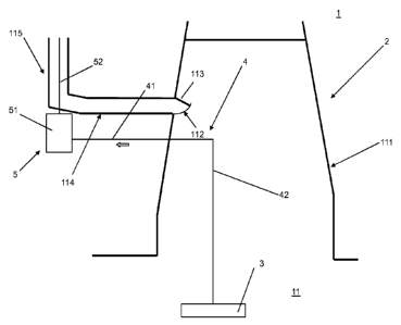
In Figure 1 a machinery arrangement for a marine vessel 1 is generally indi-
cated by reference sign 2. The machinery arrangement comprises a combustion
unit 3. The combustion unit may be a diesel engine, oil-fired boiler,
incinerator,
etc.
The combustion unit 3 is arranged in an engine room generally indicated by ref-
erence sign 11 (discussed more in detail below).
The machinery arrangement 2 comprises an exhaust duct assembly 4 for re-
ceiving an exhaust gas flow from the combustion unit 3 and for leading the ex-
haust gas flow to the atmosphere. The exhaust gases are treated by an exhaust
gas cleaning system 5 arranged in the flow direction (main intended flow direc-
tion of the exhaust gas is indicated by a block arrow) of the exhaust gas. The
exhaust gas cleaning system 5 includes a cleaning device for sulphuric oxides
(S0x), e.g. a scrubber unit 51, which is provided with an exhaust gas pipe 52.
The exhaust gas duct assembly 4 includes a first section 41 connected to and
thus leading to the exhaust gas cleaning system 5, i.e. the scrubber unit 51,
and
a second section 42 connected to and extending form the combustion unit 3.
The first section 41 is located downstream of the second section 42 in the
flow
direction of the exhaust gas, whereby the first section and the second section
connect the combustion unit 3 to the scrubber unit 51.
Further, in the present invention, the engine room 11 comprises an engine room
casing 111 with an engine room ventilation outlet 112 provided with a fire
damper 113 that can be closed, e.g. in case of fire. The engine room 11 is in
flow connection with the an enclosure 114, or more particularly, the
ventilation
outlet 112 is in flow connection with, in other words leads to the enclosure
114,
which encloses the exhaust pipe 52 of the scrubber unit 51. The enclosure 114
is advantageously located outside the fire damper 113 of the engine room cas-
CA 02717084 2010-08-26
WO 2009/125050 PCT/F12009/050190
ing 111. The enclosure is open-ended and is provided by a jacket portion 115
surrounding at least part of the exhaust gas pipe 52 of the scrubber unit 51.
The scrubber unit 51 is located outside the enclosure 114. The second section
42 of the exhaust gas duct assembly 4 is located within the engine room casing
5 111 and the first section 41 of the exhaust gas duct assembly 4 is at
least partly
located outside the engine room casing 111.
In the following the operation of the machinery arrangement according to the
invention shall shortly be described.
As the combustion unit 3 is driven, exhaust gas is generated and is led into
the
exhaust gas duct assembly 4, firstly through the second section 42 connected
to the combustion unit 3 and then forward through the first section 41
connected
to the scrubber unit 51.
In operation, a heated air flow is provided by ventilation air from the engine
room 11 through the ventilation outlet 112 into the enclosure 114. The heated
air flow flowing through the enclosure 114 towards the jacket portion 115
heats
the exhaust gas pipe 52 of the scrubber unit 51. The heated air flow is thus
led
into contact with and is mixed with the wet exhaust gas from the exhaust gas
pipe 52 which is discharged into the atmosphere. Consequently, the resulting
mixture has reduced relative humidity, reduced risk for condensed droplets, re-
duced opacity and increased buoyancy. The heated air flow also prevents cool-
ing inside the exhaust gas pipe 52, thus avoiding undesired condensation.
Depending on the desired effect of the heated air flow from the engine room
11,
the jacket portion 115 surrounds at least part of the exhaust gas pipe 52,
i.e.
advantageously ends somewhat below, at the same level, or somewhat above
the outlet of the exhaust gas pipe 52. The jacket portion 115 may also be con-
structed as a lateral support of the exhaust gas pipe 52.
In Figure 2 a machinery arrangement for a marine vessel 1 is generally indi-
cated by reference sign 2. The machinery arrangement comprises a combustion
unit 3. The combustion unit may be a diesel engine, oil-fired boiler,
incinerator,
etc.
CA 02717084 2010-08-26
WO 2009/125050 PCT/F12009/050190
6
The combustion unit 3 is arranged in an engine room generally indicated by ref-
erence sign 11 (discussed more in detail below).
The machinery arrangement 2 comprises an exhaust duct assembly 4 for re-
ceiving an exhaust gas flow from the combustion unit 3 and for leading the ex-
haust gas flow to the atmosphere. The exhaust gases are treated by an exhaust
gas cleaning system 5 arranged in the flow direction (main intended flow direc-
tion of the exhaust gas is indicated by a block arrow) of the exhaust gas. The
exhaust gas cleaning system 5 includes a cleaning device for sulphuric oxides
(S0x), e.g. a scrubber unit 51, which is provided with an exhaust gas pipe 52.
The exhaust gas duct assembly 4 includes a first section 41 connected to and
thus leading to the exhaust gas cleaning system 5, i.e. the scrubber unit 51,
and
a second section 42 connected to and extending form the combustion unit 3.
The first section 41 is located downstream of the second section 42 in the
flow
direction of the exhaust gas, whereby the first section and the second section
connect the combustion unit 3 to the scrubber unit 51.
Further, in the present invention, the engine room 11 comprises an engine room
casing 111 with an engine room ventilation outlet 112 provided with a fire
damper 113 that can be closed, e.g. in case of fire. The engine room 11 is in
flow connection with the an enclosure 114, or more particularly, the engine
room ventilation outlet 112 is in flow connection with, in other words leads
to an
enclosure 114, which encloses the first section 41 of the exhaust gas duct as-
sembly 4 as well as the exhaust pipe 52 of the scrubber unit 51. The enclosure
is open-ended and is provided by a jacket portion 115 surrounding at least
part
of the exhaust gas pipe 52 of the scrubber unit 51. The scrubber unit 51 is lo-
cated outside the enclosure 114. The second section 42 of the exhaust gas as-
sembly 4 is located within the engine room casing 111.
The enclosure 114 has a cross sectional area larger than the engine room ven-
tilation outlet 112 leading to the enclosure 114 from engine room 11. This
mini-
mizes flow resistance and impact on engine room ventilation. The enclosure
114 is advantageously located outside the fire damper 113 of the engine room
casing 111.
CA 02717084 2010-08-26
WO 2009/125050 PCT/F12009/050190
7
In the following the operation of the machinery arrangement according to the
invention shall shortly be described.
As the combustion unit 3 is driven, exhaust gas is generated and is led into
the
exhaust gas duct assembly 4, firstly through the second section 42 connected
to the combustion unit 3 and then forward through the first section 41
connected
to the scrubber unit 51.
In operation, the advantageously un-insulated first section 41 of the exhaust
gas
duct assembly 4 is ventilated by and provides additional heat to a heated air
flow provided by ventilation air from the engine room 11 through the
ventilation
outlet 112. The heated air flow flowing towards the jacket portion 115 also
heats
the exhaust gas pipe 52 of the scrubber unit 51. The heated air flow is
further
led into contact with and is thus mixed with the wet exhaust gas from the ex-
haust gas pipe 52 which is discharged into the atmosphere. Consequently, the
resulting mixture has reduced relative humidity, reduced risk for condensed
droplets, reduced opacity and increased buoyancy. The heated air flow also
prevents cooling inside the exhaust gas pipe 52, thus avoiding undesired con-
densation.
Depending on the desired effect of the heated air flow from the engine room
11,
the jacket portion 115 surrounds at least part of the exhaust gas pipe 52,
i.e.
advantageously ends somewhat below, at the same level, or somewhat above
the outlet of the exhaust gas pipe 52. The jacket portion 115 may also be con-
structed as a lateral support of the exhaust gas pipe 52.
In Figure 3 a machinery arrangement for a marine vessel 1 is generally indi-
cated by reference sign 2. The machinery arrangement comprises a combustion
unit 3, in this embodiment a number of combustion units. The combustion units
may include diesel engines, oil-fired boilers, incinerators, etc.
The combustion units are arranged in an engine room generally indicated by
reference sign 11 (discussed more in detail below).
The machinery arrangement 2 comprises an exhaust duct assembly 4 for re-
ceiving an exhaust gas flow from the combustion units and for leading the ex-
CA 02717084 2010-08-26
WO 2009/125050 PCT/F12009/050190
8
haust gas flow to the atmosphere. The exhaust gases are treated by an exhaust
gas cleaning system 5 arranged in the flow direction (main intended flow direc-
tion of the exhaust gas is indicated by a block arrow) of the exhaust gas. The
exhaust gas cleaning system includes a cleaning device for sulphuric oxides
(S0x), e.g. a scrubber unit 51, which is provided with an exhaust gas pipe 52.
The exhaust gas duct assembly 4 includes a first section 41 comprising a first
branch pipe 411 connected to and thus leading to the exhaust gas cleaning sys-
tem 5, i.e. to the scrubber unit 51, and a second section 42 comprising a sec-
ond branch pipe 421 connected to and extending from the combustion unit 3,
also leading to the atmosphere. The first section, comprising the first branch
pipe, and the second section, comprising the second branch pipe, connect the
combustion unit 3 to the scrubber unit 51, whereby the second section 42, com-
prising the second branch pipe 421, also forms a by-pass leading to the atmos-
phere through a funnel section 116 of an engine room casing 111 of the engine
room 11 (discussed more in detail below). In this embodiment, which includes a
number of combustion units, each combustion unit 3 is connected to a first
branch pipe 411 and a second branch pipe 421 respectively. A fan unit 6 is pro-
vided in flow connection with each first branch pipe 411. In this embodiment
the
fan unit 6 is arranged between the first branch pipes 411 and the exhaust gas
cleaning system 5, in a common collecting branch 43, which connects the vari-
ous first branch pipes and the scrubber unit 51.
Each of the first branch pipes 411 is provided with a first valve means 7,
which
advantageously is arranged to function as a shut-off valve and flow control
valve.
In the following the operation of the machinery arrangement according to the
invention shall shortly be described.
In operation, as one or more combustion units 3 are driven, exhaust gas is gen-
erated and is led into the exhaust gas duct assembly 4. The purpose is to draw
substantially all of the exhaust gas by the fan unit 6 through the first
branch
pipes 411 and to push the exhaust gas via the common collecting branch 43
into the scrubber unit 51 in order to clean the same. The second branch pipes
CA 02717084 2010-08-26
WO 2009/125050 PCT/F12009/050190
9
421 basically function as stand-by exhaust pipe for the respective combustion
units 3, preferably so that a minimum of fresh air is provided to the scrubber
unit
51 in order to prevent escape of un-cleaned exhaust gases.
The fan unit 6 is advantageously equipped with a frequency converter and/or
-- guide vanes for flexible control of its appropriate function in relation to
the drive
mode of the respective combustion units 3. Exhaust gas flow-back from the
common collecting branch 43 to other combustion units is controlled by the
first
valve means 7 provided in each first branch pipe 411. The first valve means 7
are arranged to balance the flow in the active first branch pipes 411, i.e.
the first
-- branch pipes connected to a driven combustion unit 3. On the other hand,
the
first valve means 7 are also arranged to shut-off the flow in the inactive
first
branch pipes 411, i.e. the first branch pipes connected to a non-operational
combustion unit 3.
This arrangement also ensures that the exhaust gas back pressure, with regard
-- to each combustion unit 3, remains about the same or slightly lower than in
a
conventional machinery installation.
In case e.g. of malfunction of the scrubber unit 51, the first valve means 7
can
be used to prevent the flow of hot exhaust gases to the scrubber unit 51. In a
situation like this, the exhaust gases can be led directly through the second
-- branch pipes 421 to the atmosphere, whereby exhaust gas emission control
may be achieved by using fuel with lower sulphur content.
Each of the second branch pipes 421 are advantageously provided with a sec-
ond valve means (not shown), a temperature sensor (not shown) and a flow
sensor (not shown).
-- The temperature sensors in the second branch pipes 421 can thus be used to
control that there is no inadvertent flow of hot, un-cleaned exhaust gases
into
the atmosphere. The flow sensors in the second branch pipes 421 can corre-
spondingly be used to control the flow of fresh air, i.e. said minimum of
fresh air
discussed above, provided to the scrubber unit 51. The second valve means
-- may regulate the flow as such in the second branch pipes.
CA 02717084 2010-08-26
WO 2009/125050 PCT/F12009/050190
For optimizing the overall operation of the exhaust gas cleaning system the
fan
unit 6, the first valve means 7, and also as appropriate the second valve
means,
the temperature sensor and the flow sensor, are connected to a central control
unit (not shown) for monitoring the exhaust gas flow.
5 In conclusion, such a central control unit provides the means to ensure
that a
minimum of fresh air continuously can be sucked backwards from the active
second branch pipes, that the air flow to and therefore the exhaust gas load
(combined air and exhaust gas flow) to the scrubber unit is minimised, and
that
power consumption can be optimised. Furthermore, by minimizing the flow of
10 cold air from the second branch pipes, any risk for condensation of
sulphuric
acid at the point of mixing of said cold air and hot exhaust gases can be
avoided. The deployment of the central control unit remains within the knowl-
edge of a person skilled in the art, and is therefore not discussed in more
detail
in this connection.
Further, in the present invention, the engine room 11 comprises an engine room
casing 111 with an engine room ventilation outlet 112 provided with a fire
damper 113 that can be closed, e.g. in case of fire. The engine room 11 is in
flow connection with the an enclosure 114, or more particularly, the engine
room ventilation outlet 112 is in flow connection, in other words leads to an
en-
closure 114, which encloses exhaust pipe 52 of the scrubber unit 51. The en-
closure 114 is advantageously located outside the fire damper of the engine
room casing 111. The enclosure is open-ended and is provided by a jacket por-
tion 115 surrounding at least part of the exhaust gas pipe 52 of the scrubber
unit 51.
The scrubber unit 51 is located outside the enclosure 114. The second branch
pipes 421 are located in the funnel portion 116 of the engine room casing 111
and the first branch pipes 411 are at least partly located outside the engine
room casing 111.
In operation, a heated air flow is provided by ventilation air from the engine
room 11 through the ventilation outlet 112 into the enclosure 114. The heated
air flow flowing through the enclosure 114 towards the jacket portion 115
heats
CA 02717084 2010-08-26
WO 2009/125050 PCT/F12009/050190
11
the exhaust gas pipe 52 of the scrubber unit 51. The heated air flow is thus
led
into contact with and is mixed with the wet exhaust gas from the exhaust gas
pipe 52 which is discharged into the atmosphere. Consequently, the resulting
mixture has reduced relative humidity, reduced risk for condensed droplets, re-
duced opacity and increased buoyancy. The heated air flow also prevents cool-
ing inside the exhaust gas pipe 52, thus avoiding undesired condensation.
Depending on the desired effect of the heated air flow from the engine room
11,
the jacket portion 115 surrounds at least part of the exhaust gas pipe 52,
i.e.
advantageously ends somewhat below, at the same level, or somewhat above
the outlet of the exhaust gas pipe 52. The jacket portion 115 may also be con-
structed as a lateral support of the exhaust gas pipe
It is clear that the number and type of combustion units can vary, whereby
they
can be connected to the same exhaust gas cleaning system. The combustion
units may also be provided with an exhaust gas boiler. In view of the location
of
the combustion units onboard a marine vessel, it is also possible to have more
than one exhaust gas cleaning system provided with a corresponding enclo-
sure.
The fan unit may alternatively be arranged after the scrubber unit 51, in the
ex-
haust gas pipe 52 of the scrubber unit. Another possibility is to arrange a
fan
unit in each of the first branch pipes 411, upstream of the valve means 7 with
regard to the flow direction (block arrow) of the exhaust gas.
In Figure 4 a machinery arrangement for a marine vessel 1 is generally indi-
cated by reference sign 2. The machinery arrangement comprises a combustion
unit 3, in this embodiment a number of combustion units. The combustion units
may include diesel engines, oil-fired boilers, incinerators, etc.
The combustion units are arranged in an engine room generally indicated by
reference sign 11 (discussed more in detail below).
The machinery arrangement 2 comprises an exhaust duct assembly 4 for re-
ceiving an exhaust gas flow from the combustion units and for leading the ex-
haust gas flow to the atmosphere. The exhaust gases are treated by an exhaust
CA 02717084 2010-08-26
WO 2009/125050 PCT/F12009/050190
12
gas cleaning system 5 arranged in the flow direction (main intended flow direc-
tion of the exhaust gas is indicated by a block arrow) of the exhaust gas. The
exhaust gas cleaning system includes a cleaning device for sulphuric oxides
(S0x), e.g. a scrubber unit 51, which is provided with an exhaust gas pipe 52.
The exhaust gas duct assembly 4 includes a first section 41 comprising a first
branch pipe 411 connected to and thus leading to the exhaust gas cleaning sys-
tem 5, i.e. to the scrubber unit 51, and a second section 42 comprising a sec-
ond branch pipe 421 connected to and extending from the combustion unit 3,
also leading to the atmosphere. The first section, comprising the first branch
pipe, and the second section, comprising the second branch pipe, connect the
combustion unit 3 to the scrubber unit 51, whereby the second section 42, com-
prising the second branch pipe 421, also forms a by-pass leading to the atmos-
phere through a funnel section 116 of an engine room casing 111 of the engine
room (discussed more in detail below). In this embodiment, which includes a
number of combustion units, each combustion unit 3 is connected to a first
branch pipe 411 and a second branch pipe 421 respectively. A fan unit 6 is pro-
vided in flow connection with each first branch pipe 411. In this embodiment
the
fan unit 6 is arranged between the first branch pipes 411 and the exhaust gas
cleaning system 5, in a common collecting branch 43, which connects the van-
ous first branch pipes and the scrubber unit 51.
Each of the first branch pipes 411 is provided with a first valve means 7,
which
advantageously is arranged to function as a shut-off valve and flow control
valve.
In the following the operation of the machinery arrangement according to the
invention shall shortly be described.
In operation, as one or more combustion units 3 are driven, exhaust gas is gen-
erated and is led into the exhaust gas duct assembly 4. The purpose is to draw
substantially all of the exhaust gas by the fan unit 6 through the first
branch
pipes 411 and to push the exhaust gas via the common collecting branch 43
into the scrubber unit 51 in order to clean the same. The second branch pipes
421 basically function as stand-by exhaust pipe for the respective combustion
CA 02717084 2010-08-26
WO 2009/125050 PCT/F12009/050190
13
units 3, preferably so that a minimum of fresh air is provided to the scrubber
unit
51 in order to prevent escape of un-cleaned exhaust gases.
The fan unit 6 is advantageously equipped with a frequency converter and/or
guide vanes for flexible control of its appropriate function in relation to
the drive
mode of the respective combustion units 3. Exhaust gas flow-back from the
common collecting branch 43 to other combustion units is controlled by the
first
valve means 7 provided in each first branch pipe 411. The first valve means 7
are arranged to balance the flow in the active first branch pipes 411, i.e.
the first
branch pipes connected to a driven combustion unit 3. On the other hand, the
first valve means 7 are also arranged to shut-off the flow in the inactive
first
branch pipes 411, i.e. the first branch pipes connected to a non-operational
combustion unit 3.
This arrangement also ensures that the exhaust gas back pressure, with regard
to each combustion unit 3, remains about the same or slightly lower than in a
conventional machinery installation.
In case e.g. of malfunction of the scrubber unit 51, the first valve means 7
can
be used to prevent the flow of hot exhaust gases to the scrubber unit 51. In a
situation like this, the exhaust gases can be led directly through the second
branch pipes 421 to the atmosphere, whereby exhaust gas emission control
may be achieved by using fuel with lower sulphur content.
Each of the second branch pipes 421 are advantageously provided with a sec-
ond valve means (not shown), a temperature sensor (not shown) and a flow
sensor (not shown).
The temperature sensors in the second branch pipes 421 can thus be used to
control that there is no inadvertent flow of hot, un-cleaned exhaust gases
into
the atmosphere. The flow sensors in the second branch pipes 421 can corre-
spondingly be used to control the flow of fresh air, i.e. said minimum of
fresh air
discussed above, provided to the scrubber unit 51. The second valve means
may regulate the flow as such in the second branch pipes.
CA 02717084 2010-08-26
WO 2009/125050 PCT/F12009/050190
14
For optimizing the overall operation of the exhaust gas cleaning system the
fan
unit 6, the first valve means 7, and also as appropriate the second valve
means,
the temperature sensor and the flow sensor, are connected to a central control
unit (not shown) for monitoring the exhaust gas flow.
In conclusion, such a central control unit provides the means to ensure that a
minimum of fresh air continuously can be sucked backwards from the active
second branch pipes, that the air flow to and therefore the exhaust gas load
(combined air and exhaust gas flow) to the scrubber unit is minimised, and
that
power consumption can be optimised. Furthermore, by minimizing the flow of
cold air from the second branch pipes, any risk for condensation of sulphuric
acid at the point of mixing of said cold air and hot exhaust gases can be
avoided. The deployment of the central control unit remains within the knowl-
edge of a person skilled in the art, and is therefore not discussed in more
detail
in this connection.
Further, in the present invention, the engine room 11 comprises an engine room
casing 111 with an engine room ventilation outlet 112 provided with a fire
damper 113 that can be closed, e.g. in case of fire. The engine room 11 is in
flow connection with the an enclosure 114, or more particularly, the engine
room ventilation outlet 112 is in flow connection, in other words leads to an
en-
closure 114, which surrounds the first branch pipes 411 as well as the exhaust
pipe 52 of the scrubber unit 51. The enclosure is open-ended and is provided
by
a jacket portion 115 surrounding at least part of the exhaust gas pipe 52 of
the
scrubber unit 51. In this embodiment, the fan unit 6 is also arranged within
the
enclosure 114. The scrubber unit 51 is located outside the enclosure 114. The
second branch pipes 421 are located in the funnel portion 116 of the engine
room casing 111.
The enclosure 114 has a cross sectional area larger than the engine room ven-
tilation outlet 112 leading to the enclosure 114 from engine room 11. This
mini-
mizes flow resistance and impact on engine room ventilation. The enclosure
114 is advantageously located outside the fire damper of the engine room cas-
ing 111.
CA 02717084 2010-08-26
WO 2009/125050 PCT/F12009/050190
In operation, the advantageously un-insulated first branch pipes 411 are venti-
lated by and provide additional heat to a heated air flow provided by
ventilation
air from the engine room 11 through the ventilation outlet 112. The heated air
flow flowing towards the jacket portion 115 also heats the exhaust gas pipe 52
5 of the scrubber unit 51. The heated air flow is further led into contact
with and is
mixed with the wet exhaust gas from the exhaust gas pipe 52 which is dis-
charged into the atmosphere. Consequently, the resulting mixture has reduced
relative humidity, reduced risk for condensed droplets, reduced opacity and in-
creased buoyancy. The heated air flow also prevents cooling inside the exhaust
10 gas pipe 52, thus avoiding undesired condensation.
Depending on the desired effect of the heated air flow from the engine room
11,
the jacket portion 115 surrounds at least part of the exhaust gas pipe 52,
i.e.
advantageously ends somewhat below, at the same level, or somewhat above
the outlet of the exhaust gas pipe 52. The jacket portion 115 may also be con-
15 structed as a lateral support of the exhaust gas pipe
It is clear that the number and type of combustion units can vary, whereby
they
can be connected to the same exhaust gas cleaning system. The combustion
units may also be provided with an exhaust gas boiler. In view of the location
of
the combustion units onboard a marine vessel, it is also possible to have more
than one exhaust gas cleaning system provided with a corresponding enclo-
sure.
The fan unit may alternatively be arranged after the scrubber unit 51, in the
ex-
haust gas pipe 52 of the scrubber unit. Another possibility is to arrange a
fan
unit in each of the first branch pipes 411, upstream of the valve means 7 with
regard to the flow direction (block arrow) of the exhaust gas.
In view of all the embodiments discussed above, it may be noted that an ex-
haust gas cleaning system can use a scrubber unit that is run with sea water,
fresh water, or a combination of both. The scrubber unit material can be corro-
sion resistant metal or glass-fibre reinforced plastic (GRP), whereby the
latter
has advantages in view of its lightness, as it is located high up in the
marine
vessel.
CA 02717084 2010-08-26
WO 2009/125050 PCT/F12009/050190
16
The description and thereto related drawings are only intended to clarify the
ba-
sic idea of the present invention. The invention may vary in detail within the
scope of the ensuing claims.