Note: Descriptions are shown in the official language in which they were submitted.
CA 02717123 2010-08-30
WO 2009/109031 PCT/CA2008/001206
1
PIVOTABLY DETACHABLE HARDWOOD FLOORBOARDS
FIELD OF THE INVENTION
The application relates generally to hardwood floorboard assemblies and, more
particularly,
to a new hardwood flooring tongue and groove arrangement.
BACKGROUND ART
In the hardwood floor industry, two main types of hardwood floor are found on
the market, 1)
solid wood and 2) engineered wood composed of superposed layers of wood. Solid
hardwood floorboards are manufactured pre-finished or unfinished. In the pre-
finished
hardwood floor, the sanding and varnishing process is done at the factory by
opposition to the
unfinished flooring where the sanding and varnishing are executed on-site
after installation of
the hardwood flooring.
The manufacturing process of pre-finished hardwood floor includes varnishing
and/or
staining steps on assembled floorboard sections of typically 4 feet wide.
These sections
allow effective use of sanding techniques prior to or concomitant with the
varnishing and/or
staining steps. There is a need for the manufacturers, to have a tight
assembly of the tongue
and groove joint between each adjoining floor boards to prevent the same from
becoming
disassembled from one another during the sanding and varnishing process.
During the varnishing process, the floorboards can be assembled and
disassembled 2 to 3
times prior to its final packaging. The manufacturers also traditionally
packed the
floorboards in 4 layers of 3 or 4 wide assembled floorboard panels. There is
thus also a need
for facilitating the separation of the floor boards into layers of 3 or 4
assembled floorboard
panels without damaging the tongue and groove joint.
The requirement of having a tight assembly of the tongue and groove joint
during the sanding
operation is a major inconvenient for floorboards installers who need to
disassemble the
floorboard packages before the installation. If excessive force is used to
separate the
floorboards, especially those who were exposed to humidity, by applying
excessive force, it
may cause permanent damage to the tongue and groove joint and/or result in an
increase of
disassembling time and efforts for the installers.
CA 02717123 2010-08-30
WO 2009/109031 PCT/CA2008/001206
2
None of the traditional floorboards are designed to provide a solid board
assembly to prevent
disengagement of the individual floor boards during the factory sanding
process while still
providing for easy disassembly of the pre-finished floorboards into floorboard
sections of 3
or 4 floorboard panels prior to packaging and/or into individual floor boards
prior the
installation. If prior-art tongue and groove designs were made to ease
detachment of
floorboards, they could not insure a tight assembly during the manufacturing
or installation.
There is thus a need to provide floorboards with tight assembly of the tongue
and groove joint
for the manufacturing process while remaining easy to detach at the time of
installing the
hardwood flooring.
SUMMARY
In view of the foregoing, it would be desirable to provide a tightly assembled
tongue and
groove joint to prevent individual floorboards from being disassembled during
factory
sanding and varnishing operations while providing for relatively easy manual
separation of
the boards by the contractor at the time of installation.
Those contradictory requirements can be met for a tongue-and-groove design
that provides a
firm grip and a tight assembly of floorboards to insure quality of processing
at varnishing,
while allowing ease of disassembling by a simple rotational or pivotal
movement of the
floorboards to ease the work of the installer without modifying the
traditional way of
installation.
According to a general aspect, there is thus provided a floorboard assembly
comprising: at
least first and second hardwood floor boards adapted to be mounted in a side-
by-side
coplanar relationship, the first floor board having a tongue extending
longitudinally along a
first side thereof, the second floor board having a groove extending
longitudinally along a
second side thereof, the groove having a width defined between a top lip and a
bottom lip, the
tongue being received in a tight fit manner in the groove to provide
frictional resistance
against translational separation of the first and second floor boards in a
common plane
thereof, a top surface of the tongue being in frictional engagement with an
undersurface of
the top lip of the groove from a top outermost contact point to a top
innermost contact point,
a bottom surface of the tongue being in frictional engagement with a top
surface of the
bottom lip of the groove from a bottom outermost contact point to a bottom
innermost contact
point, the top outermost contact point and the bottom innermost contact point
defining a first
CA 02717123 2010-08-30
WO 2009/109031 PCT/CA2008/001206
3
diagonal, the top innermost contact point and the bottom outermost contact
point defining a
second diagonal, one of said first and second diagonals having a length
sufficiently greater
than the width of the groove to substantially lock the first and second floor
boards against
relative pivotal movement in one of an upward or a downward direction
associated with said
one of said first and second diagonals, and a clearance provided between the
tongue and the
groove, the clearance reducing the length of the other one of said first and
second diagonals
to approximate the width of the groove to permit an angular withdrawal of the
tongue from
the groove by manually pivoting the first and second boards toward each other
in the other
one of said upward and downward directions.
According to a further general aspect, there is provided a pre-finished
floorboard assembly
comprising at least first and second solid wood floor boards, the first floor
board having a
tongue extending longitudinally along a first side thereof, the second floor
board having a
groove extending longitudinally along a second side thereof, the groove having
a width
defined between a top lip and a bottom lip, the tongue being insertable in
frictional
engagement in the groove to counteract pull-apart forces exerted on the first
and second floor
boards during factory sanding and varnishing operations, and at least one play
provided
between the tongue and the groove at one of a tip portion of the tongue and an
outermost
portion of the top and bottom lips of the groove, the play being configured to
allow the
tongue to be angularly withdrawn from the groove by manually pivoting the
first and second
floor boards towards one another in only one of an upward and a downward
direction.
The term "floor board" should not be strictly construed to the preliminary
meaning of the
word and is intended to broadly refer to any floor planks, floor strips and
the like used in the
fabrication of a hardwood flooring.
Floor boards can be made from different hardwood essence, such as pin, oak,
maple, wild
cherry, cherry, birch and walnut. It is understood that the present invention
is not limited to
only those commonly available wood species.
BRIEF DESCRIPTION OF THE DRAWINGS
Reference will now be made to the accompanying drawings in which:
Figure 1 is a cross-sectional view of a prior art hardwood floorboard assembly
illustrating a
tongue-and-groove interconnection between two adjacent solid wood planks;
CA 02717123 2010-08-30
WO 2009/109031 PCT/CA2008/001206
4
Figure 2 is a cross-sectional view of a hardwood floorboard assembly
illustrating a lip
clearance angle of a tongue and groove joint between two adjoining floor
boards in
accordance with an embodiment of the present invention;
Figure 3 is a cross-sectional view of a floorboard assembly illustrating
another possible way
of providing a lip clearance angle for enabling pivotal disassembly of two
adjoining floor
boards;
Figure 4 is a cross-sectional view of the floor boards shown in Fig. 3 but
illustrated in an
unassembled state in order to illustrate some of the geometrical
characteristics of the tongue-
and-groove joint;
Figures 5a to 5c are cross-sectional views illustrating in sequence the
pivotal disengagement
of the floor boards shown in Fig. 3;
Figures 6a and 6b are cross-sectional views illustrating the retaining action
between the floor
boards of Fig. 3 when subject to downward bending forces as well as the
retaining action
when subject to pull apart forces exerted in the plane of the floor boards;
Figures 7a to 7c illustrate various ways of providing the lip clearance angle
required to permit
withdrawal of the tongue from the groove in response to a relative pivotal
movement of the
floor boards; and
Figure 8 is a cross-sectional view of a downwardly pivotally separable floor
board assembly
in accordance with a further embodiment of the present invention.
DESCRIPTION OF THE PREFERRED EMBODIMENTS
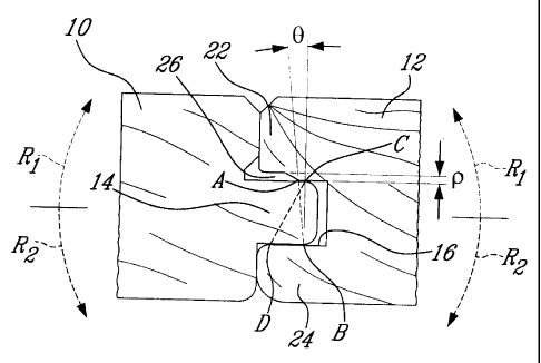
Fig. 1 shows a prior art tongue and groove joint of the type used to
interconnect solid wood
boards in a coplanar relationship to form hardwood flooring. More
particularly, Fig. I shows
first and second adjoining floor boards 10 and 12. Each floor board panel 10,
12 has a tongue
14 extending axially along a first longitudinal side thereof and a groove 16
extending axially
along an opposite longitudinal side thereof for receiving the tongue 14 of an
adjacent floor
board, as is well know in the art. As shown in Fig. 1, the tongue 14 of the
first floor board 10
is frictionally engaged in the groove 16 of the second floor board 12 in order
to maintain the
first and second floor boards 10 and 12 in a coplanar side-by-side
relationship. The tongue 14
has parallel top and bottom surfaces 18 and 20 which are respectively in
frictional
CA 02717123 2010-08-30
WO 2009/109031 PCT/CA2008/001206
engagement with the top and bottom lips 22 and 24 of groove 16. As can be
appreciated from
Fig. 1, the top outermost contact point A, between the tongue top surface 18
and the groove
top lip 22, and the diagonally opposed bottom innermost contact point B,
between the tongue
bottom surface 20 and the groove bottom lip 24, cooperate to lock the first
and second floor
5 boards 10 and 12 against relative upward pivotal movement, as depicted by
arrows R1. The
length of line AB is too great as compared to the width of the groove 16 (i.e.
the distance
between the top and bottom lips 22 and 24) to permit any upward pivotal or
tilting movement
of the tongue 14 in the groove 16. Likewise, the top innermost contact point
C, between the
tongue top surface 18 and the groove top lip 22, and the diagonally opposed
bottom
outermost contact point D, between the tongue bottom surface 20 and the groove
bottom lip
24, cooperate to lock the first and second floor boards 10 and 12 against
relative downward
pivotal movement, as depicted by arrows R2. Again, the length of line CD is
significantly
greater than the width of the groove 16, thereby preventing downward pivotal
movement of
the tongue 14 in the groove 16 and that even for soft wood species exhibiting
relatively high
level of compressibility. The difference between the length of lines AB and CD
and the width
of the groove 16 is simply too important -to allow any upward or downward
pivotal
movement of the tongue 14 in the groove 16. By analogy, it would be like
trying to fit a 6 feet
long vertical beam between 5 feet spaced-apart top and bottom beams.
Accordingly, the only way of disassembling the floor boards 10 and 12 without
breaking the
tongue 14 or the lips 22, 24 of the groove 16 is to pull apart the boards 10
and 12 by applying
withdrawal forces in the plane of the boards 10 and 12 in a direction opposite
to a direction of
insertion of the tongue 14 in the groove 16, as depicted by arrows Pi and P2.
The top and
bottom frictional surfaces respectively defined between: 1) top contact points
A and C and 2)
bottom contact points D and B, provide resistance against the linear
withdrawal of the tongue
14 from the groove 16. It can be appreciated that the distance between top
contact points A
and C is equal to the distance between bottom contact points D and B. The
tighter the fit
between the tongue 14 and the groove 16, the greater the forces P1 and P2 must
be to separate
the floor boards 10 and 12. A tight fit is particularly desirable where the
floor boards are to
be pre-finished (factory finished). If a loose fit is provided, the boards run
the risk of
becoming disengaged from one another during the sanding and varnishing
procedures,
thereby resulting in poor quality finish. However, once on-site, it is
desirable for the boards to
be easily separable to facilitate the installation thereof. The above tongue
and groove joint
arrangement with planar disengagement of the boards does not meet the above
contradictory
CA 02717123 2010-08-30
WO 2009/109031 PCT/CA2008/001206
6
needs. Therefore, compromises had heretofore to be made between a good quality
finish and
easy installation.
Turning to Fig. 2, there is shown an embodiment of a new tongue and groove
joint which still
provides resistance against coplanar disengagement of the floor boards 10 and
12 while
allowing easy separation of the floor boards 10 and 12 by a simple upward
pivotal action. As
will be seen hereinafter, the tongue and groove joint has been modified to
permit an upward
pivoting or tilting movement of the tongue 14 in the groove 16, thereby
allowing easy
withdrawal of the tongue 14 from the groove 16.
It can be appreciated from Fig. 2, that the length of diagonal line AB can be
shortened, for
instance, by displacing the top outermost contact point A inwardly towards the
bottom of the
groove 16 (towards the right hand side on Fig. 2). By doing so, line AB is
pivoted about the
innermost bottom point B to a position closer to the vertical, thereby
resulting in a shortening
of the line AB to a dimension which is closer to the width of the groove B.
When the length
of line AB is sufficiently close to the width dimension of the groove 16, it
becomes possible
to disengage the floor boards 10 and 12 by simply pivoting the boards 10 and
12 towards
each other in an upward direction, as illustrated in Figs. 5a to 5c. The angle
0 between line
AB and the vertical is herein referred to as a lip clearance angle. The lip
clearance angle 0 can
be generally defined as the angle which permits pivotal disengagement of the
floor boards 10
and 12 in one of the upward or downward direction, while still providing
sufficient contact
surfaces between the tongue 14 and the groove 16 to counteract planar pulling-
apart of the
floor boards during factory sanding/varnishing operations.
It has been found that pivotal separation of the floor boards 10 and 12 can be
achieved
without risking breaking the tongue 14 or the lips 22 and 24 of the groove 16
for lip clearance
angles 0 up to about 20 degrees. It is understood that this upper limit may
vary depending on
the level of compressibility of the wood species used to form the floor
boards. For instance,
soft wood species, such as pine, may permit slightly greater lip clearance
angle. It has also
been noticed that the effort required to pivotally separate the floor boards
10 and 12
noticeably increases for clearance angles 0 greater than 16 degrees. A 16
degrees lip
clearance angle corresponds for instance to a 0.07 inch long top contact line
AC for a 0.240
inch groove opening (i.e. distance between top and bottom lips 22 and 24 of
the groove 16)
in the example illustrated in Fig. 2.
CA 02717123 2010-08-30
WO 2009/109031 PCT/CA2008/001206
7
It has also been found that if the lip clearance angle 0 becomes too small
(i.e. the distance
between the top outermost and innermost contact point A and C in Fig. 2), the
planar
retention benefit afforded by the frictional engagement of the tongue 14 in
the groove 16 is
lost. Such a planar retention lost should be avoided in order to prevent
disengagement of the
floor boards 10 and 12 during the sanding and varnishing operations. Tests
have shown that
the floor boards become subject to coplanar separation during factory sanding
and varnishing
operation for tip clearance angles smaller than about 12 degrees. This
corresponds to a 0.05
inch long top contact line AC for a 0.240 inch groove opening. The best
results (i.e. easy
pivotal separation with good planar retention) have been obtained for a lip
clearance angle of
about 14 degrees. In Fig. 2, this can also be expressed in term of a ratio
between the length of
the top contact surface (length of line AC) and the width or opening of the
groove 16. A 14
degrees lip clearance angle corresponds to a `/ ratio. For instance, for a
groove having a
0.240 inch width or opening, line AC would be 0.060 inch long.
In the embodiment illustrated in Fig. 2, the desired lip clearance angle 0 is
obtained by
machining an undercut 26 in the outermost edge portion of the undersurface of
the top lip 22
of the groove 16. As will be seen hereinafter, the undercut 26 may have
several
configurations. The undercut 26 defines a play P to permit withdrawal of the
tongue 14 from
the groove 16 via a relative upward pivotal movement of the floor boards 10
and 12. For
instance, a 0.05 inch play P can be used for 0.240 inch groove opening and a
0.06 inch top
contact line AC (i.e. 14 degrees lip clearance angle). With such a tongue and
groove
configuration, the tongue 14 can be tightly received in the groove 16 to
provide strong planar
retention of the floor boards 10 and 12 while allowing for easy pivotal
separation of the floor
boards 10 and 12 in the upward direction, as illustrated by arrows R1.
However, any attempts
at separating the floor boards 10 and 12 by means of downward pivotal
movement, as
represented by arrows R2, will be blocked by the contact points C and D. The
line CD has not
been altered by the modification made in the groove upper lip 22. As can be
appreciated in
Fig. 2, line CD is significantly longer than line AB and way too long compared
to the groove
opening to permit any downward pivotal movement of the tongue 14 in the groove
16.
Accordingly, the pivotal movement of the tongue 14 in the groove 16 has been
unlocked in
only one direction (i.e. the upward direction).
As shown in Fig. 3, the desired lip clearance angle 0 can also be obtained by
machining both
the groove top lip 22 and the undersurface 20 of the tip portion of the tongue
14. According
to this embodiment, the position of both the top outermost contact point A and
of the bottom
CA 02717123 2010-08-30
WO 2009/109031 PCT/CA2008/001206
8
innermost contact point B is modified in order to reduce the length of line
AB. The
embodiment shown in Fig. 3 essentially differs from the embodiment of Fig. 2
by the
addition of a second undercut 28 in the undersurface 20 of the tip of the
tongue 14. The
second undercut 28 displaces the bottom innermost contact point B away from
the bottom of
the groove 16 that is to the left hand side on Fig. 3. By so displacing the
bottom innermost
contact point B in an outward direction relative to the groove 16, the top
outermost contact
point A can be displaced to a lesser extend inwardly toward the bottom of the
groove 16. By
comparing Figs. 2 and 3, it can be seen that the undercut 26' (Fig. 3) is not
as deep as
undercut 26 (Fig. 2). In contrast to the embodiment of Fig. 2 where only the
top contact line
AC is shortened, the total length reduction of the contact surfaces between
the tongue 14 and
the groove 16 is shared by both the top and bottom contact lines AC and DB (in
a proportion
of for instance 70% on the top contact surface and 30% on the bottom contact
surface).
According to the embodiment of Fig. 3, the resistance against planar
separation of the floor
boards 10 and 12 is more evenly shared by the top and bottom contact surfaces
represented
by lines AC and DB (in Fig. 2 the top contact surface AC is significantly
shorter than the
bottom contact surface DB). As for the first embodiment, the floor boards 10
and 12 can be
easily pivotally disengaged from one another in the upward direction, as
indicated by arrows
R1. Pivotal disengagement or separation is however once again prevented in the
downward
direction (arrows R2) by the contact points C and D which are not affected by
undercuts 26'
and 28.
As shown in Fig. 3, a third undercut 29 can be defined in the undersurface of
the bottom lip
24 along all the extent of the lip in a depth wise direction of the groove 16
(see L4 in Fig.4).
The third undercut 29 provides added flexibility of the bottom lip 24 to
facilitate the insertion
and the withdrawal of the tongue 14 in the groove 16. According to the
illustrated
embodiment, the third undercut 29 provides a bottom lip thickness reduction of
about 0.020
inch to about 0.030. The play created by the third undercut 29 facilitates the
insertion of the
bottom lip 24 of the groove 16 underneath the tongue 14 after the board 10 has
been nailed
down to the sub floor structure. The third undercut can also compensate for
expansion of the
tongue 14 or of the groove lips due to environmental factors such as humidity.
The third
undercut 29 also contributes to minimise the risk of breaking the groove lips
or the tongue
when a board has to be removed.
Fig. 4 shows some of the geometrical details of the embodiment of Fig. 3. The
length L1 of
the second undercut 28 can represent about 15 % to about 30% of the length L2
of the tongue
CA 02717123 2010-08-30
WO 2009/109031 PCT/CA2008/001206
9
14. The reduction in the tongue thickness TI can represent about 5% to about
20% of the
total thickness T2 of the tongue 14. The transition angle 6 defined by the
undercut 28 can be
about 10 to 50 degrees.
The length L3 of the lip undercut 26' can represent 15% to 30% of the length
or deepness L4
of the groove 16. The play P' defined by the first undercut 26' can represent
5% to 20% of
the width W of the groove 16. A play P' of at least 0.020 inch can be made in
the
undersurface of the upper lip of groove 16 for a 0.240 inch groove width W.
The transition
angle 0 defined by the undercut 26' can be about 10 to 50 degrees.
Figs. 5a and 5c illustrate the procedure for pivotally separating the floor
boards 10 and 12
shown in Figs. 3 and 4. One has simply to grab the boards 10 and 12 by the
sides thereof
opposite to their adjoining edges and to exert an upward folding or pivoting
action, as
represented by arrows RI. The width of each floor boards 10 and 12 acts as a
lever to
facilitate the relative pivotal movement of the floor boards 10 and 12 about
an initial point of
pivot corresponding to a point of contact 30 between the top upper lip 22 of
floor board 12
and the confronting side face of the other floor board 10. The lip undercut
26' and the tongue
undercut 28 provide the required clearance to permit the angular withdrawal
movement of the
tongue 14 from the groove 16, thereby allowing for easy separation of the
floor boards 10 and
12, as shown in Figs. 5b and Sc.
However, if downward pivotal efforts are applied on the floor boards 10 and 12
as
represented by arrows R2 in Fig. 6a or if manual pull-apart forces P1 and P2
are applied in
the plane of the floor boards 10 and 12 as shown in Fig. 6b, the tight fit
engagement of the
tongue 14 in the groove 16 will restrain the board against becoming disengaged
from one
another, as explained hereinbefore.
Figs. 7a and 7c illustrate various possible tongue and groove configurations
that could be
implemented to provide a desired lip clearance angle 0 between the tongue and
the groove of
adjacent floor boards. Figs. 7a and 7c are not intended to constitute an
exhaustive
representation of all the possible alternatives. A person skilled in the art
will understand that
various permutations or combinations of the illustrated undercut arrangements
can be
provided to permit pivotal disengagement of the floor boards in one of an
upward or
downward direction while still restraining linear removal of a board tongue
from the
associated groove of an adjacent board.
CA 02717123 2010-08-30
WO 2009/109031 PCT/CA2008/001206
Now referring more particularly to Figs. 7a to 7c, it can be seen that the
upward pivotal
movement can also be unlocked by solely adding one undercut 32, 32' or 32" in
the
undersurface of the tip portion of the tongue 14.
Irrespective of their emplacement (on the tongue or the lip of the groove) the
undercut can
5 have various profiles. For instance, the undercut can have a stepped profile
(Fig. 7a), a
slanted or bevel profile (Fig. 7b), or a rounded or are profile (Fig. 7c).
These profiles as well
as other suitable profiles could also be applied to the undercut 26 defined in
the undersurface
of the groove upper lip 22 shown in Fig. 2. The person skilled in the art will
understand that a
wide variety of profiles could be adopted.
10 Fig. 8 illustrates one example of a downwardly pivotable tongue and groove
arrangement.
According to this embodiment, the diagonal AB remains unchanged as compared to
line AB
on Fig. 1. The length of line AB is significantly longer than the width of the
groove 16 and
thus upward pivotal movement, as represented by arrows R1, of the tongue 14 in
the groove
16 is impossible without breaking the tongue 14 or the lips 22 and 24 of the
groove 16.
However, relative downward pivotal movement of the floor boards 10 and 12 as
represented
by arrows R2 is rendered possible by the shortening of the contact line CD. In
the illustrated
example, the shortening is accomplished by means of a slanted undercut 36 on
the top of the
tip portion of the tongue 14 and a two-step undercut 38 on the outmost portion
of the top
surface of the bottom lip 24 of the groove 16. The lip clearance angle 0 is
defined between
line CD and the vertical and like the lip clearance angle for unlocking the
upward pivotal
movement, it is comprised in range extending from about 12 degrees to about 20
degrees.
The above described tongue and groove arrangement is advantageous in that it
can be
retrofitted" or adapted to any conventional tongue and groove arrangements.
Also, it does
not necessitate the purchase of any special tooling apart from new cutting
knives having a
cutting edge profile corresponding to the additional undercuts to be defined
in the
floorboards. It also facilitates the verification of the planarity between two
adjoining boards
since the tongue and groove engagement can be made very tight. The above
described tongue
and groove arrangement also reduces the likelihood that the floorboards being
returned to the
manufacturer by the installers because the boards are too difficult to
separate from one
another. It also contributes to improve the quality of the finish of factory
finished floor
boards by ensuring a greater integrity of the connection between the boards
during the
sanding and varnishing operations.
CA 02717123 2010-08-30
WO 2009/109031 PCT/CA2008/001206
11
Still further embodiments and modifications of the present invention are
available. The scope
of the appended claims is not intended to be limited, therefore, only to the
specific exemplary
embodiments described above.