Note: Descriptions are shown in the official language in which they were submitted.
CA 02718112 2010-09-09
WO 2009/124083 PCT/US2009/039016
1
METHOD AND SYSTEM FOR FACILITATING EXECUTION OF
AUTOMATIC NEIGHBOR RELATION FUNCTIONS
CROSS-REFERENCE TO RELATED APPLICATIONS
[0001] This application claims the benefit of U.S. Provisional Patent
application
Serial No. 61/040,845 entitled "APPARATUS AND METHODS FOR ANR
FUNCTION IN THE LTE NETWORKS," which was filed March 31, 2008.
BACKGROUND
I. Field
[0002] The present application relates generally to wireless
communications,
and more specifically to a method and system for facilitating execution of
automatic
neighbor relation (ANR) functions in a Long Term Evolution (LTE) system.
II. Background
[0003] Wireless communication systems are widely deployed to provide
various
types of communication content such as voice, data, and so on. These systems
may be
multiple-access systems capable of supporting communication with multiple
users by
sharing the available system resources (e.g., bandwidth and transmit power).
Examples
of such multiple-access systems include code division multiple access (CDMA)
systems, time division multiple access (TDMA) systems, frequency division
multiple
access (FDMA) systems, 3GPP Long Term Evolution (LTE) systems, and orthogonal
frequency division multiple access (OFDMA) systems.
[0004] Generally, a wireless multiple-access communication system can
simultaneously support communication for multiple wireless terminals. In such
a
system, each terminal can communicate with one or more base stations via
transmissions on the forward and reverse links. The forward link (or downlink)
refers
to the communication link from the base stations to the terminals, and the
reverse link
(or uplink) refers to the communication link from the terminals to the base
stations.
This communication link can be established via a single-in-single-out (SISO),
multiple-
in-signal-out (MISO), or a multiple-in-multiple-out (MIMO) system.
[0005] A MIMO system employs multiple (NT) transmit antennas and
multiple
(NR) receive antennas for data transmission. A MIMO channel formed by the NT
CA 02718112 2010-09-09
WO 2009/124083 PCT/US2009/039016
2
transmit and NR receive antennas may be decomposed into Ns independent
channels,
which are also referred to as spatial channels, where Ns min{NT, NR } . Each
of the
Ns independent channels corresponds to a dimension. The MIMO system can
provide
improved performance (e.g., higher throughput and/or greater reliability) if
the
additional dimensionalities created by the multiple transmit and receive
antennas are
utilized.
[0006] A MIMO system supports a time division duplex (TDD) and frequency
division duplex (FDD) systems. In a TDD system, the forward and reverse link
transmissions are on the same frequency region so that the reciprocity
principle allows
the estimation of the forward link channel from the reverse link channel. This
enables
the access point to extract transmit beamforming gain on the forward link when
multiple
antennas are available at the access point.
[0007] The rapidly evolving complexity of LTE systems has placed
increased
demands on the operation and maintenance of LTE networks. Within the context
of
neighbor relations, manual efforts to configure a base station's neighbor list
will thus
soon be unsustainable. Accordingly, it would be desirable to have a method and
apparatus directed towards automatically updating a neighbor list so that
human
interaction can be reduced and the capacity of the network can be increased.
SUMMARY
[0008] The following presents a simplified summary of one or more
embodiments in order to provide a basic understanding of such embodiments.
This
summary is not an extensive overview of all contemplated embodiments, and is
intended to neither identify key or critical elements of all embodiments nor
delineate the
scope of any or all embodiments. Its sole purpose is to present some concepts
of one or
more embodiments in a simplified form as a prelude to the more detailed
description
that is presented later.
[0009] In accordance with one or more embodiments and corresponding
disclosure thereof, various aspects are described in connection with
facilitating
managing cells in a multi-carrier system. In one aspect, a method, apparatus,
and
computer program product is disclosed for facilitating execution of automatic
neighbor
relation (ANR) functions from a base station. Within such embodiment, the base
station
receives neighbor cell detection data from an access terminal, which
identifies neighbor
CA 02718112 2013-05-23
74769-3083
3
cells detected by the access terminal. The base station also receives neighbor
cell
management data from an operation and maintenance (OAM) system, which includes
data
that facilitates performing at least one ANR function. The base station then
automatically
updates a neighbor list as a function of the neighbor cell management data and
the neighbor
cell detection data.
[0010] In another aspect, a method, apparatus, and computer program
product is
disclosed for facilitating execution of ANR functions in a base station from
an OAM system.
Within such embodiment, the OAM system receives ANR data from the base
station, which
includes neighbor cell detection data and/or neighbor list report data. The
neighbor cell
detection data identifies neighbor cells detected by an access terminal,
whereas the neighbor
list report data includes a summary of updates made to a neighbor list. The
OAM system
generates neighbor cell management data as a function of the ANR data, which
includes data
that facilitates performing at least one ANR function. The OAM system then
transmits the
neighbor cell management data to the base station.
[0010a] According to one aspect of the present invention, there is provided
a method
for a base station in a wireless network to facilitate execution of automatic
neighbor relation
(ANR) functions, comprising: receiving neighbor cell detection data from an
access terminal,
the neighbor cell detection data identifying neighbor cells detected by the
access terminal;
transmitting a neighbor list report to an operation and maintenance (OAM)
system, the
neighbor list report including a summary of updates made to a neighbor list;
receiving
neighbor cell management data from the OAM system, the neighbor cell
management data
including data that facilitates performing at least one ANR function; and
automating an update
of the neighbor list as a function of the neighbor cell management data and
the neighbor cell
detection data.
[0010b] According to another aspect of the present invention, there is
provided a base
station for facilitating execution of automatic neighbor relation (ANR)
functions in a wireless
system, comprising: a radio resource control (RRC) component configured to
facilitate
communications between the base station and an access terminal, the RRC
component
configured to receive neighbor cell detection data from the access terminal,
the neighbor cell
CA 02718112 2013-05-23
74769-3083
3a
detection data identifying neighbor cells detected by the access terminal; an
interface
component configured to facilitate communications between the base station and
an operation
and maintenance (OAM) system, the interface component configured to transmit a
neighbor
list report to the OAM system, the neighbor list report including a summary of
updates made
to a neighbor list, the interface component configured to receive neighbor
cell management
data from the OAM system, the neighbor cell management data including data
that facilitates
performing at least one ANR function; and an ANR function component configured
to
automatically update the neighbor list as a function of the neighbor cell
management data and
the neighbor cell detection data.
[0010c] According to still another aspect of the present invention, there
is provided a
computer program product for facilitating execution of automatic neighbor
relation (ANR)
functions in a wireless system from a base station, comprising: a computer-
readable storage
medium storing computer executable instructions thereon that when executed by
a computer
perform the steps of: receiving neighbor cell detection data from an access
terminal, the
neighbor cell detection data identifying neighbor cells detected by the access
terminal;
transmitting a neighbor list report to an operation and maintenance (OAM)
system, the
neighbor list report including a summary of updates made to a neighbor list:
receiving
neighbor cell management data from the OAM system, the neighbor cell
management data
including data that facilitates performing at least one ANR function; and
automating an update
of the neighbor list as a function of the neighbor cell management data and
the neighbor cell
detection data.
[0010d] According to yet another aspect of the present invention,
there is provided an
apparatus for facilitating execution of automatic neighbor relation (ANR)
functions in a
wireless system from a base station, comprising: means for receiving neighbor
cell detection
data from an access terminal, the neighbor cell detection data identifying
neighbor cells
detected by the access terminal; means for transmitting a neighbor list report
to an operation
and maintenance (OAM) system, the neighbor list report including a summary of
updates
made to a neighbor list: means for receiving neighbor cell management data
from the OAM
system, the neighbor cell management data including data that facilitates
performing at least
CA 02718112 2013-05-23
74769-3083
3b
one ANR function; and means for automating an update of the neighbor list as a
function of
the neighbor cell management data and the neighbor cell detection data.
[0010e] According to a further aspect of the present invention, there
is provided a
method for an operation and maintenance (OAM) system in a wireless network to
facilitate
execution of automatic neighbor relation (ANR) functions in a base station,
comprising:
receiving ANR data from the base station, the ANR data including at least one
of neighbor
cell detection data or neighbor list report data, the neighbor cell detection
data identifying
neighbor cells detected by an access terminal, the neighbor list report data
including a
summary of updates made to a neighbor list, the ANR data including the
neighbor list report
data; generating neighbor cell management data, the neighbor cell management
data generated
as a function of the ANR data and including data that facilitates performing
at least one ANR
function; and transmitting the neighbor cell management data to the base
station.
[0010f] According to yet a further aspect of the present invention,
there is provided an
operation and maintenance (OAM) system for facilitating execution of automatic
neighbor
relation (ANR) functions in a base station, comprising: a receiving component
configured to
facilitate receiving ANR data from the base station, the ANR data including at
least one of
neighbor cell detection data or neighbor list report data, the neighbor cell
detection data
identifying neighbor cells detected by an access terminal, the neighbor list
report data
including a summary of updates made to a neighbor list, the ANR data including
the neighbor
list report data; an ANR manager component configured to generate neighbor
cell
management data, the neighbor cell management data generated as a function of
the ANR data
and including data that facilitates performing at least one ANR function; a
transmitting
component configured to transmit the neighbor cell management data to the base
station.
[0010g1 According to still a further aspect of the present invention,
there is provided a
computer program product for facilitating execution of automatic neighbor
relation (ANR)
functions in a base station from an operation and maintenance (OAM) system,
comprising: a
computer-readable storage medium storing computer executable instructions
thereon that
when executed by a computer perform the steps of: receiving ANR data from the
base station,
the ANR data including at least one of neighbor cell detection data or
neighbor list report data,
CA 02718112 2013-05-23
74769-3083
3c
the neighbor cell detection data identifying neighbor cells detected by an
access terminal, the
neighbor list report data including a summary of updates made to a neighbor
list, the ANR
data including the neighbor list report data; generating neighbor cell
management data, the
neighbor cell management data generated as a function of the ANR data and
including data
that facilitates performing at least one ANR function; and transmitting the
neighbor cell
management data to the base station.
[0010h] According to another aspect of the present invention, there is
provided an
apparatus for facilitating execution of automatic neighbor relation (ANR)
functions in a base
station from an operation and maintenance (OAM) system, comprising: means for
receiving
ANR data from the base station, the ANR data including at least one of
neighbor cell
detection data or neighbor list report data, the neighbor cell detection data
identifying
neighbor cells detected by an access terminal, the neighbor list report data
including a
summary of updates made to a neighbor list, the ANR data including the
neighbor list report
data; means for generating neighbor cell management data, the neighbor cell
management
data generated as a function of the ANR data and including data that
facilitates performing at
least one ANR function; and means for transmitting the neighbor cell
management data to the
base station.
[0011] To the accomplishment of the foregoing and related ends, the
one or more
embodiments comprise the features hereinafter fully described and particularly
pointed out in
the claims. The following description and the annexed drawings set forth in
detail certain
illustrative aspects of the one or more embodiments. These aspects are
indicative, however,
of but a few of the various ways in which the principles of various
embodiments can be
employed and the described embodiments are intended to include all such
aspects and their
equivalents.
BRIEF DESCRIPTION OF THE DRAWINGS
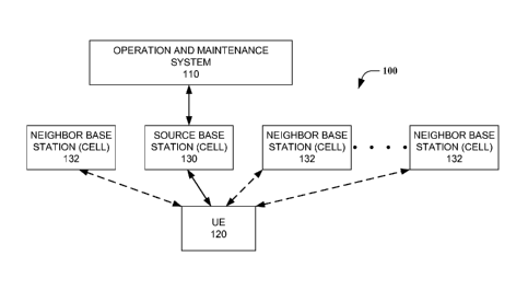
[0012] FIG. 1 is an illustration of an exemplary wireless
communication system for
facilitating execution of ANR functions in accordance with an embodiment.
CA 02718112 2013-05-23
74769-3083
3d
[0013] FIG. 2 is a block diagram of an exemplary base station unit in
accordance with
an embodiment.
[0014] FIG. 3 is an illustration of an exemplary coupling of
electrical components that
facilitates execution of ANR functions in a base station in accordance with an
embodiment.
[0015] FIG. 4 is a block diagram of an exemplary OAM system in accordance
with an
embodiment.
CA 02718112 2010-09-09
WO 2009/124083 PCT/US2009/039016
4
[0016] FIG. 5 is an illustration of an exemplary coupling of electrical
components that facilitates execution of ANR functions in an OAM system in
accordance with an embodiment.
[0017] FIG. 6 is an exemplary schematic of a distributed model for
facilitating
execution of ANR functions.
[0018] FIG. 7 is an exemplary schematic of a centralized model for
facilitating
execution of ANR functions.
[0019] FIG. 8 is an exemplary schematic of a hybrid model for
facilitating
execution of ANR functions.
[0020] FIG. 9 is an illustration of a wireless communication system in
accordance with various aspects set forth herein.
[0021] FIG. 10 is an illustration of an exemplary wireless network
environment
that can be employed in conjunction with the various systems and methods
described
herein.
[0022] FIG. 11 is an illustration of an exemplary base station in
accordance with
various aspects described herein.
[0023] FIG. 12 is an illustration of an exemplary wireless terminal
implemented
in accordance with various aspects described herein.
DETAILED DESCRIPTION
[0024] Various embodiments are now described with reference to the
drawings,
wherein like reference numerals are used to refer to like elements throughout.
In the
following description, for purposes of explanation, numerous specific details
are set
forth in order to provide a thorough understanding of one or more embodiments.
It may
be evident, however, that such embodiment(s) may be practiced without these
specific
details. In other instances, well-known structures and devices are shown in
block
diagram form in order to facilitate describing one or more embodiments.
[0025] The techniques described herein can be used for various wireless
communication systems such as code division multiple access (CDMA), time
division
multiple access (TDMA), frequency division multiple access (FDMA), orthogonal
frequency division multiple access (OFDMA), single carrier-frequency division
multiple access (SC-FDMA), High Speed Packet Access (HSPA), and other systems.
The terms "system" and "network" are often used interchangeably. A CDMA system
CA 02718112 2010-09-09
WO 2009/124083 PCT/US2009/039016
can implement a radio technology such as Universal Terrestrial Radio Access
(UTRA),
CDMA2000, etc. UTRA includes Wideband-CDMA (W-CDMA) and other variants of
CDMA. CDMA2000 covers IS-2000, IS-95 and IS-856 standards. A TDMA system
can implement a radio technology such as Global System for Mobile
Communications
(GSM). An OFDMA system can implement a radio technology such as Evolved UTRA
(E-UTRA), Ultra Mobile Broadband (UMB), IEEE 802.11 (Wi-Fi), IEEE 802.16
(WiMAX), IEEE 802.20, Flash-OFDM, etc. UTRA and E-UTRA are part of Universal
Mobile Telecommunication System (UMTS). 3GPP Long Term Evolution (LTE) is an
upcoming release of UMTS that uses E-UTRA, which employs OFDMA on the
downlink and SC-FDMA on the uplink.
[0026] Single carrier frequency division multiple access (SC-FDMA)
utilizes
single carrier modulation and frequency domain equalization. SC-FDMA has
similar
performance and essentially the same overall complexity as those of an OFDMA
system. A SC-FDMA signal has lower peak-to-average power ratio (PAPR) because
of
its inherent single carrier structure. SC-FDMA can be used, for instance, in
uplink
communications where lower PAPR greatly benefits access terminals in terms of
transmit power efficiency. Accordingly, SC-FDMA can be implemented as an
uplink
multiple access scheme in 3GPP Long Term Evolution (LTE) or Evolved UTRA.
[0027] High speed packet access (HSPA) can include high speed downlink
packet access (HSDPA) technology and high speed uplink packet access (HSUPA)
or
enhanced uplink (EUL) technology and can also include HSPA+ technology. HSDPA,
HSUPA and HSPA+ are part of the Third Generation Partnership Project (3GPP)
specifications Release 5, Release 6, and Release 7, respectively.
[0028] High speed downlink packet access (HSDPA) optimizes data
transmission from the network to the user equipment (UE). As used herein,
transmission from the network to the user equipment UE can be referred to as
the
"downlink" (DL). Transmission methods can allow data rates of several Mbits/s.
High
speed downlink packet access (HSDPA) can increase the capacity of mobile radio
networks. High speed uplink packet access (HSUPA) can optimize data
transmission
from the terminal to the network. As used herein, transmissions from the
terminal to the
network can be referred to as the "uplink" (UL). Uplink data transmission
methods can
allow data rates of several Mbit/s. HSPA+ provides even further improvements
both in
the uplink and downlink as specified in Release 7 of the 3GPP specification.
High
CA 02718112 2010-09-09
WO 2009/124083 PCT/US2009/039016
6
speed packet access (HSPA) methods typically allow for faster interactions
between the
downlink and the uplink in data services transmitting large volumes of data,
for instance
Voice over IP (VoIP), videoconferencing and mobile office applications
[0029] Fast data transmission protocols such as hybrid automatic repeat
request,
(HARQ) can be used on the uplink and downlink. Such protocols, such as hybrid
automatic repeat request (HARQ), allow a recipient to automatically request
retransmission of a packet that might have been received in error.
[0030] Various embodiments are described herein in connection with an
access
terminal. An access terminal can also be called a system, subscriber unit,
subscriber
station, mobile station, mobile, remote station, remote terminal, mobile
device, user
terminal, terminal, wireless communication device, user agent, user device, or
user
equipment (UE). An access terminal can be a cellular telephone, a cordless
telephone, a
Session Initiation Protocol (SIP) phone, a wireless local loop (WLL) station,
a personal
digital assistant (PDA), a handheld device having wireless connection
capability,
computing device, or other processing device connected to a wireless modem.
Moreover, various embodiments are described herein in connection with a base
station.
A base station can be utilized for communicating with access terminal(s) and
can also
be referred to as an access point, Node B, Evolved Node B (eNodeB) or some
other
terminology.
[0031] Referring next to Fig. 1, an illustration of an exemplary
wireless
communication system for facilitating execution of ANR functions in accordance
with
an embodiment is provided. As illustrated, system 100 may include an operation
and
maintenance (OAM) device 110 in communication with each of a plurality of base
stations 130 and 132. In a first embodiment, source base station 130 relies on
UE 120
to detect cells that that are not currently in its neighbor list (e.g., cells
serviced by any of
base stations 132). In another embodiment, because neighbor relations are cell-
based,
the neighbor list can be cell-specific (i.e., each cell can have its own
neighbor list),
although the ANR function is base station-based. Moreover, it is possible to
have an
ANR function manage multiple neighbor lists (e.g., one for each cell). Under
either
embodiment, UE 120 may be instructed by base station 130 to measure/report on
any of
several types of cells including the serving cell, listed cells (i.e., cells
indicated by the E-
UTRAN as part of the list of neighboring cells), and detected cells (i.e.,
cells not
indicated by the E-UTRAN but detected by the UE).
CA 02718112 2010-09-09
WO 2009/124083 PCT/US2009/039016
7
[0032] Referring next to Fig. 2, a block diagram of an exemplary base
station
unit in accordance with an embodiment is provided. As illustrated, base
station unit 200
may include processor component 210, memory component 220, radio resource
control
(RRC) component 230, OAM interface component 240, and ANR function component
250.
[0033] In one aspect, processor component 210 is configured to execute
computer-readable instructions related to performing any of a plurality of
functions.
Processor component 210 can be a single processor or a plurality of processors
dedicated to analyzing information to be communicated from base station unit
200
and/or generating information that can be utilized by memory component 220,
radio
resource control (RRC) component 230, OAM interface component 240, and/or ANR
function component 250. Additionally or alternatively, processor component 210
may
be configured to control one or more components of base station unit 200.
[0034] In another aspect, memory component 220 is coupled to processor
component 210 and configured to store computer-readable instructions executed
by
processor component 210. Memory component 220 may also be configured to store
any
of a plurality of other types of data including data generated/obtained by any
of radio
resource control (RRC) component 230, OAM interface component 240, and/or ANR
function component 250. Memory component 220 can be configured in a number of
different configurations, including as random access memory, battery-backed
memory,
hard disk, magnetic tape, etc. Various features can also be implemented upon
memory
component 220, such as compression and automatic back up (e.g., use of a
Redundant
Array of Independent Drives configuration).
[0035] As illustrated, base station unit 200 also includes RRC component
230
which is coupled to processor component 210 and configured to interface base
station
unit 200 with any of a plurality of access terminals. In a particular
embodiment, RRC
component 230 is configured to facilitate communications between the base
station unit
200 and an access terminal, wherein measurements pertaining to cells detected
by an
access terminal are requested and received from the access terminal via RRC
component 230. For instance, RRC component 230 may instruct the access
terminal to
ascertain the global ID of a cell detected by the access terminal, wherein
such
instructions may reference a physical ID corresponding to particular
measurements
received from the access terminal.
CA 02718112 2010-09-09
WO 2009/124083 PCT/US2009/039016
8
[0036] In another aspect, base station unit 200 also includes OAM
interface
component 240. Here, OAM interface component 240 is configured to facilitate
communications between the base station unit 200 and an OAM system. Within
such
embodiment, OAM interface component 240 may be configured to receive any of a
plurality of types of neighbor cell management data from the OAM. Indeed, for
some
embodiments, OAM interface component 240 may receive data that facilitates an
internal processing of ANR functions (e.g., an ANR handover
blacklist/whitelist and/or
an ANR X2 blacklist/whitelistmay be received for processing by the base
station unit
200), whereas other embodiments may include receiving data encapsulating an
external
processing of ANR functions (e.g., receiving explicit commands from the OAM on
how
to update the neighbor list). OAM interface component 240 may also be
configured to
report updates to the OAM system, which summarize neighbor list updates
implemented
by base station unit 200.
[0037] In yet another aspect, base station 200 includes ANR function
component 250 which is configured to perform any of a plurality of ANR
functions.
Within such embodiment, ANR function component 250 may include any of a
plurality
of subcomponents to perform various ANR functions. For instance, a neighbor
detection subcomponent may be included to interface with RRC component 230,
wherein detection data is routed from RRC component 230 to either an OAM
system
(i.e., for external processing) or a subcomponent within base station unit 200
(i.e., for
internal processing). For internal processing, an exemplary configuration of
ANR
function component 250 may thus include a handover relations subcomponent
and/or an
X2 relations subcomponent coupled to the neighbor detection subcomponent. An
update subcomponent may also be included to implement update requests, wherein
such
requests may include internal requests (e.g., requests from the handover
relations
subcomponent and/or the X2 relations subcomponent) and/or external requests
(e.g.,
requests from the OAM system).
[0038] Turning to Fig. 3, illustrated is a system 300 that facilitates
execution of
ANR functions in accordance with aspects disclosed herein. System 300 can
reside
within a base station, for instance. As depicted, system 300 includes
functional blocks
that can represent functions implemented by a processor, software, or
combination
thereof (e.g., firmware). System 300 includes a logical grouping 302 of
electrical
components that can act in conjunction. As illustrated, logical grouping 302
can include
CA 02718112 2010-09-09
WO 2009/124083 PCT/US2009/039016
9
an electrical component for receiving neighbor cell detection data from an
access
terminal 310. Further, logical grouping 302 can include an electrical
component for
receiving neighbor cell management data from an OAM system 312, as well as an
electrical component for automating an update of a neighbor list based on the
neighbor
cell detection data and the neighbor cell management data 314. Additionally,
system
300 can include a memory 320 that retains instructions for executing functions
associated with electrical components 310, 312, and 314. While shown as being
external to memory 320, it is to be understood that electrical components 310,
312, and
314 can exist within memory 320.
[0039] Referring next to Fig. 4, a block diagram of an exemplary OAM
system
in accordance with an embodiment is provided. As illustrated, OAM system 400
may
include processor component 410, memory component 420, receiving component
430,
ANR manager component 440, and transmitting component 450.
[0040] Similar to processor component 210 in base station unit 200,
processor
component 410 is configured to execute computer-readable instructions related
to
performing any of a plurality of functions. Processor component 410 can be a
single
processor or a plurality of processors dedicated to analyzing information to
be
communicated from OAM system 400 and/or generating information that can be
utilized by memory component 420, receiving component 430, ANR manager
component 440, and/or transmitting component 450. Additionally or
alternatively,
processor component 410 may be configured to control one or more components of
OAM system 400.
[0041] In another aspect, memory component 420 is coupled to processor
component 410 and configured to store computer-readable instructions executed
by
processor component 410. Memory component 420 may also be configured to store
any
of a plurality of other types of data including data generated/obtained by any
of
receiving component 430, ANR manager component 440, and/or transmitting
component 450. Here, it should be noted that memory component 420 is analogous
to
memory component 220 in base station unit 200. Accordingly, it should be
appreciated
that any of the aforementioned features/configurations of memory component 220
are
also applicable to memory component 420.
[0042] As illustrated, OAM system 400 also includes receiving component
430
and transmitting component 450. In an aspect, receiving component 430 is
configured
CA 02718112 2010-09-09
WO 2009/124083 PCT/US2009/039016
to receive any of a plurality of types of data from any of a plurality of base
stations,
whereas transmitting component 450 is configured to transmit any of a
plurality of types
of data to any of a plurality of base stations. As stated previously with
respect to base
station 200, data received via receiving component 430 may include detection
data
routed from a neighbor detection subcomponent and/or updates reported to OAM
system 400 summarizing neighbor list updates implemented by the base
station(s) .
Similarly, as was also stated with respect to base station 200, data
transmitted via
transmitting component 450 may include an ANR handover blacklist/whitelist
and/or an
ANR X2 blacklist/whitelist for processing by the base station(s), as well as
explicit
update commands processed by OAM system 400.
[0043] In another aspect, OAM system 400 includes ANR manager component
440 which is configured to generate any of a plurality of types of management
data for
facilitating performing any of various ANR functions. Namely, ANR manager
component 440 may be configured to generate the aforementioned ANR handover
blacklists/whitelists, ANR X2 blacklists/whitelists, and/or explicit update
commands.
To this end, ANR manager component 440 may include a network manager layer in
communication with an elements manager layer, wherein the elements manager
layer
may include a handover relations subcomponent and/or X2 relations subcomponent
for
performing ANR functions similar to ANR function component 250.
[0044] Referring next to Fig. 5, illustrated is another system 500 that
facilitates
execution of ANR functions in accordance with aspects disclosed herein. System
500
can reside within an OAM system, for instance. Similar to system 300, system
500
includes functional blocks that can represent functions implemented by a
processor,
software, or combination thereof (e.g., firmware), wherein system 500 includes
a logical
grouping 502 of electrical components that can act in conjunction. As
illustrated,
logical grouping 502 can include an electrical component for receiving
neighbor cell
detection data from an access terminal 510. Further, logical grouping 502 can
include
an electrical component for receiving neighbor cell management data from an
OAM
system 512, as well as an electrical component for automating an update of a
neighbor
list based on the neighbor cell detection data and the neighbor cell
management data
514. Additionally, system 500 can include a memory 520 that retains
instructions for
executing functions associated with electrical components 510, 512, and 514,
wherein
CA 02718112 2010-09-09
WO 2009/124083
PCT/US2009/039016
11
any of electrical components 510, 512, and 514 can exist either within or
outside
memory 520.
[0045] Referring next to Fig. 6 an exemplary schematic of a distributed
model
for facilitating execution of ANR functions is provided. Within such
embodiment,
execution of ANR functions is concentrated in the base station. As
illustrated, an eNB
includes an ANR function component comprising various subcomponents. In
particular, the eNB is shown to include a subcomponent for neighbor cell
detection,
handover relations, X2 relations, and neighbor list updates.
[0046] As illustrated, the neighbor cell detection subcomponent is
coupled to an
RRC component which receives and requests neighbor cell data from access
terminals.
Neighbor cell data received from the RRC component is then input from the
detection
subcomponent to the handover relations subcomponent and the X2 relations
subcomponent.
[0047] For this particular embodiment, the eNB determines whether to
add/remove Handover Relations and X2 relations from a neighbor list. With
respect to
the Handover Relations, such updates should comply with constraints set by an
ANR
whitelist/blacklist provided by the OAM, wherein Physical and Global IDs of
cells are
added/removed from the neighbor list as determined by the handover relations
subcomponent. Similarly, with respect to the X2 Relations, such updates should
comply with constraints set by an ANR X2 blacklist/whitelist provided by the
OAM,
wherein the address of a target eNB/cell to be added/removed from the neighbor
list is
determined by the X2 relations subcomponent. Here, it should be appreciated
that, if
necessary, an IP address lookup for a target eNB/cell can be performed in the
element
manager (EM) or network manager (NM) layer of the OAM, as shown.
[0048] In another aspect, the eNB informs the OAM of updates to the
neighbor
list. Upon receiving a neighbor list update from the eNB, the OAM may in turn
update
the ANR whitelist/blacklist and ANR X2 blacklist/whitelist. As illustrated,
the updated
ANR whitelist/blacklist and ANR X2 blacklist/whitelist may then be provided to
the
eNB for subsequent ANR processing.
[0049] With respect to functionality in the OAM, it should be
appreciated that
neighbor list update reports from the eNB are visible to both the EM layer and
NM
layer. It should also be appreciated that the ANR X2 blacklist/whitelist and
ANR
whitelist/blacklist can be sent from NM layer to EM layer and from EM to eNB,
CA 02718112 2010-09-09
WO 2009/124083 PCT/US2009/039016
12
wherein a negotiation is possible between the NM layer and the EM layer
regarding
each. For instance, if the EM Layer wants to update the ANR X2
blacklist/whitelist
based on local information, this negotiation functionality allow the EM layer
to do so
and report it to the NM layer.
[0050] Referring next to Fig. 7 an exemplary schematic of a centralized
model
for facilitating execution of ANR functions is provided. Within such
embodiment,
execution of ANR functions is concentrated in the OAM. For this particular
example,
the OAM includes the aforementioned handover relations subcomponent and X2
relations subcomponent, as shown. Here, upon receiving detection data from the
RRC,
the neighbor detection subcomponent of the eNB routes this detection data to
the OAM
for further processing. With respect to Handover Relations, Physical and
Global IDs of
cells are thus added/removed from the neighbor list as determined by the
handover
relations subcomponent residing in the OAM. Similarly, with respect to the X2
Relations, the address of a target eNB/cell to be added/removed from the
neighbor list is
determined by the X2 relations subcomponent residing in the OAM. All other
aspects
of the centralized model are substantially similar to the distributed model.
[0051] Referring next to Fig. 8 an exemplary schematic of a hybrid model
for
facilitating execution of ANR functions is provided. Within such embodiment,
execution of ANR functions is shared between the OAM and the base station. For
this
particular example, the handover relations subcomponent resides in the eNB,
whereas
the X2 relations subcomponent resides in the OAM. Here, upon receiving
detection
data from the RRC, the neighbor detection subcomponent routes the detection
data to
both the handover relations subcomponent in the eNB and the X2 relations
subcomponent in the OAM. With respect to Handover Relations, Physical and
Global
IDs of cells are thus added/removed from the neighbor list as determined by
the
handover relations subcomponent residing in the eNB. However, with respect to
the X2
Relations, the address of a target eNB/cell to be added/removed from the
neighbor list is
determined by the X2 relations subcomponent residing in the OAM. All other
aspects
of the hybrid model are substantially similar to both the distributed model
and the
centralized model.
[0052] Referring now to Fig. 9, a wireless communication system 900 is
illustrated in accordance with various embodiments presented herein. System
900
comprises a base station 902 that can include multiple antenna groups. For
example,
CA 02718112 2010-09-09
WO 2009/124083 PCT/US2009/039016
13
one antenna group can include antennas 904 and 906, another group can comprise
antennas 908 and 910, and an additional group can include antennas 912 and
914. Two
antennas are illustrated for each antenna group; however, more or fewer
antennas can be
utilized for each group. Base station 902 can additionally include a
transmitter chain
and a receiver chain, each of which can in turn comprise a plurality of
components
associated with signal transmission and reception (e.g., processors,
modulators,
multiplexers, demodulators, demultiplexers, antennas, etc.), as will be
appreciated by
one skilled in the art.
[0053] Base station 902 can communicate with one or more access
terminals
such as access terminal 916 and access terminal 922; however, it is to be
appreciated
that base station 902 can communicate with substantially any number of access
terminals similar to access terminals 916 and 922. Access terminals 916 and
922 can
be, for example, cellular phones, smart phones, laptops, handheld
communication
devices, handheld computing devices, satellite radios, global positioning
systems,
PDAs, and/or any other suitable device for communicating over wireless
communication system 900. As depicted, access terminal 916 is in communication
with
antennas 912 and 914, where antennas 912 and 914 transmit information to
access
terminal 916 over a forward link 918 and receive information from access
terminal 916
over a reverse link 920. Moreover, access terminal 922 is in communication
with
antennas 904 and 906, where antennas 904 and 906 transmit information to
access
terminal 922 over a forward link 924 and receive information from access
terminal 922
over a reverse link 926. In a frequency division duplex (FDD) system, forward
link 918
can utilize a different frequency band than that used by reverse link 920, and
forward
link 924 can employ a different frequency band than that employed by reverse
link 926,
for example. Further, in a time division duplex (TDD) system, forward link 918
and
reverse link 920 can utilize a common frequency band and forward link 924 and
reverse
link 926 can utilize a common frequency band.
[0054] Each group of antennas and/or the area in which they are
designated to
communicate can be referred to as a sector of base station 902. For example,
antenna
groups can be designed to communicate to access terminals in a sector of the
areas
covered by base station 902. In communication over forward links 918 and 924,
the
transmitting antennas of base station 902 can utilize beamforming to improve
signal-to-
noise ratio of forward links 918 and 924 for access terminals 916 and 922.
Also, while
CA 02718112 2010-09-09
WO 2009/124083 PCT/US2009/039016
14
base station 902 utilizes beamforming to transmit to access terminals 916 and
922
scattered randomly through an associated coverage, access terminals in
neighboring
cells can be subject to less interference as compared to a base station
transmitting
through a single antenna to all its access terminals.
[0055] Fig. 10 shows an example wireless communication system 1000. The
wireless communication system 1000 depicts one base station 1010 and one
access
terminal 1050 for sake of brevity. However, it is to be appreciated that
system 1000 can
include more than one base station and/or more than one access terminal,
wherein
additional base stations and/or access terminals can be substantially similar
or different
from example base station 1010 and access terminal 1050 described below. In
addition,
it is to be appreciated that base station 1010 and/or access terminal 1050 can
employ the
systems and/or methods described herein to facilitate wireless communication
there
between.
[0056] At base station 1010, traffic data for a number of data streams
is
provided from a data source 1012 to a transmit (TX) data processor 1014.
According to
an example, each data stream can be transmitted over a respective antenna. TX
data
processor 1014 formats, codes, and interleaves the traffic data stream based
on a
particular coding scheme selected for that data stream to provide coded data.
[0057] The coded data for each data stream can be multiplexed with pilot
data
using orthogonal frequency division multiplexing (OFDM) techniques.
Additionally or
alternatively, the pilot symbols can be frequency division multiplexed (FDM),
time
division multiplexed (TDM), or code division multiplexed (CDM). The pilot data
is
typically a known data pattern that is processed in a known manner and can be
used at
access terminal 1050 to estimate channel response. The multiplexed pilot and
coded
data for each data stream can be modulated (e.g., symbol mapped) based on a
particular
modulation scheme (e.g., binary phase-shift keying (BPSK), quadrature phase-
shift
keying (QPSK), M-phase-shift keying (M-PSK), M-quadrature amplitude modulation
(M-QAM), etc.) selected for that data stream to provide modulation symbols.
The data
rate, coding, and modulation for each data stream can be determined by
instructions
performed or provided by processor 1030.
[0058] The modulation symbols for the data streams can be provided to a
TX
MIMO processor 1020, which can further process the modulation symbols (e.g.,
for
OFDM). TX MIMO processor 1020 then provides NT modulation symbol streams to NT
CA 02718112 2010-09-09
WO 2009/124083 PCT/US2009/039016
transmitters (TMTR) 1022a through 1022t. In various embodiments, TX MIMO
processor 1020 applies beamforming weights to the symbols of the data streams
and to
the antenna from which the symbol is being transmitted.
[0059] Each transmitter 1022 receives and processes a respective symbol
stream
to provide one or more analog signals, and further conditions (e.g.,
amplifies, filters,
and upconverts) the analog signals to provide a modulated signal suitable for
transmission over the MIMO channel. Further, NT modulated signals from
transmitters
1022a through 1022t are transmitted from NT antennas 1024a through 1024t,
respectively.
[0060] At access terminal 1050, the transmitted modulated signals are
received
by NR antennas 1052a through 1052r and the received signal from each antenna
1052 is
provided to a respective receiver (RCVR) 1054a through 1054r. Each receiver
1054
conditions (e.g., filters, amplifies, and downconverts) a respective signal,
digitizes the
conditioned signal to provide samples, and further processes the samples to
provide a
corresponding "received" symbol stream.
[0061] An RX data processor 1060 can receive and process the NR received
symbol streams from NR receivers 1054 based on a particular receiver
processing
technique to provide NT "detected" symbol streams. RX data processor 1060 can
demodulate, deinterleave, and decode each detected symbol stream to recover
the traffic
data for the data stream. The processing by RX data processor 1060 is
complementary
to that performed by TX MIMO processor 1020 and TX data processor 1014 at base
station 1010.
[0062] A processor 1070 can periodically determine which available
technology
to utilize as discussed above. Further, processor 1070 can formulate a reverse
link
message comprising a matrix index portion and a rank value portion.
[0063] The reverse link message can comprise various types of
information
regarding the communication link and/or the received data stream. The reverse
link
message can be processed by a TX data processor 1038, which also receives
traffic data
for a number of data streams from a data source 1036, modulated by a modulator
1080,
conditioned by transmitters 1054a through 1054r, and transmitted back to base
station
1010.
[0064] At base station 1010, the modulated signals from access terminal
1050
are received by antennas 1024, conditioned by receivers 1022, demodulated by a
CA 02718112 2010-09-09
WO 2009/124083 PCT/US2009/039016
16
demodulator 1040, and processed by a RX data processor 1042 to extract the
reverse
link message transmitted by access terminal 1050. Further, processor 1030 can
process
the extracted message to determine which precoding matrix to use for
determining the
beamforming weights.
[0065] Processors 1030 and 1070 can direct (e.g., control, coordinate,
manage,
etc.) operation at base station 1010 and access terminal 1050, respectively.
Respective
processors 1030 and 1070 can be associated with memory 1032 and 1072 that
store
program codes and data. Processors 1030 and 1070 can also perform computations
to
derive frequency and impulse response estimates for the uplink and downlink,
respectively.
[0066] Fig. 11 illustrates an exemplary base station 1100 in accordance
with
various aspects. Base station 1100 implements tone subset allocation
sequences, with
different tone subset allocation sequences generated for respective different
sector types
of the cell. The base station 1100 includes a receiver 1102, a transmitter
1104, a
processor 1106, e.g., CPU, an input/output interface 1108 and memory 1110
coupled
together by a bus 1109 over which various elements 1102, 1104, 1106, 1108, and
1110
may interchange data and information.
[0067] Sectorized antenna 1103 coupled to receiver 1102 is used for
receiving
data and other signals, e.g., channel reports, from wireless terminals
transmissions from
each sector within the base station's cell. Sectorized antenna 1105 coupled to
transmitter 1104 is used for transmitting data and other signals, e.g.,
control signals,
pilot signal, beacon signals, etc. to wireless terminals 1200 (see Figure 12)
within each
sector of the base station's cell. In various aspects, base station 1100 may
employ
multiple receivers 1102 and multiple transmitters 1104, e.g., an individual
receiver 1102
for each sector and an individual transmitter 1104 for each sector. Processor
1106, may
be, e.g., a general purpose central processing unit (CPU). Processor 1106
controls
operation of base station 1100 under direction of one or more routines 1118
stored in
memory 1110 and implements the methods. I/O interface 1108 provides a
connection to
other network nodes, coupling the BS 1100 to other base stations, access
routers, AAA
server nodes, etc., other networks, and the Internet. Memory 1110 includes
routines
1118 and data/information 1120.
[0068] Data/ information 1120 includes data 1136, tone subset allocation
sequence information 1138 including downlink strip-symbol time information
1140 and
CA 02718112 2010-09-09
WO 2009/124083 PCT/US2009/039016
17
downlink tone information 1142, and wireless terminal (WT) data/info 1144
including a
plurality of sets of WT information: WT 1 info 1146 and WT N info 1160. Each
set of
WT info, e.g., WT 1 info 1146 includes data 1148, terminal ID 1150, sector ID
1152,
uplink channel information 1154, downlink channel information 1156, and mode
information 1158.
[0069] Routines 1118 include communications routines 1122 and base
station
control routines 1124. Base station control routines 1124 includes a scheduler
module
1126 and signaling routines 1128 including a tone subset allocation routine
1130 for
strip-symbol periods, other downlink tone allocation hopping routine 1132 for
the rest
of symbol periods, e.g., non strip-symbol periods, and a beacon routine 1134.
[0070] Data 1136 includes data to be transmitted that will be sent to
encoder
1114 of transmitter 1104 for encoding prior to transmission to WTs, and
received data
from WTs that has been processed through decoder 1112 of receiver 1102
following
reception. Downlink strip-symbol time information 1140 includes the frame
synchronization structure information, such as the superslot, beaconslot, and
ultraslot
structure information and information specifying whether a given symbol period
is a
strip-symbol period, and if so, the index of the strip-symbol period and
whether the
strip-symbol is a resetting point to truncate the tone subset allocation
sequence used by
the base station. Downlink tone information 1142 includes information
including a
carrier frequency assigned to the base station 1100, the number and frequency
of tones,
and the set of tone subsets to be allocated to the strip-symbol periods, and
other cell and
sector specific values such as slope, slope index and sector type.
[0071] Data 1148 may include data that WT1 1200 has received from a peer
node, data that WT 1 1200 desires to be transmitted to a peer node, and
downlink
channel quality report feedback information. Terminal ID 1150 is a base
station 1100
assigned ID that identifies WT 11200. Sector ID 1152 includes information
identifying
the sector in which WT1 1200 is operating. Sector ID 1152 can be used, for
example, to
determine the sector type. Uplink channel information 1154 includes
information
identifying channel segments that have been allocated by scheduler 1126 for
WT1 1200
to use, e.g., uplink traffic channel segments for data, dedicated uplink
control channels
for requests, power control, timing control, etc. Each uplink channel assigned
to WT1
1200 includes one or more logical tones, each logical tone following an uplink
hopping
sequence. Downlink channel information 1156 includes information identifying
CA 02718112 2010-09-09
WO 2009/124083 PCT/US2009/039016
18
channel segments that have been allocated by scheduler 1126 to carry data
and/or
information to WT1 1200, e.g., downlink traffic channel segments for user
data. Each
downlink channel assigned to WT1 1200 includes one or more logical tones, each
following a downlink hopping sequence. Mode information 1158 includes
information
identifying the state of operation of WT1 1200, e.g. sleep, hold, on.
[0072] Communications routines 1122 control the base station 1100 to
perform
various communications operations and implement various communications
protocols.
Base station control routines 1124 are used to control the base station 1100
to perform
basic base station functional tasks, e.g., signal generation and reception,
scheduling, and
to implement the steps of the method of some aspects including transmitting
signals to
wireless terminals using the tone subset allocation sequences during the strip-
symbol
periods.
[0073] Signaling routine 1128 controls the operation of receiver 1102
with its
decoder 1112 and transmitter 1104 with its encoder 1114. The signaling routine
1128 is
responsible controlling the generation of transmitted data 1136 and control
information.
Tone subset allocation routine 1130 constructs the tone subset to be used in a
strip-
symbol period using the method of the aspect and using data/info 1120
including
downlink strip-symbol time info 1140 and sector ID 1152. The downlink tone
subset
allocation sequences will be different for each sector type in a cell and
different for
adjacent cells. The WTs 1200 receive the signals in the strip-symbol periods
in
accordance with the downlink tone subset allocation sequences; the base
station 1100
uses the same downlink tone subset allocation sequences in order to generate
the
transmitted signals. Other downlink tone allocation hopping routine 1132
constructs
downlink tone hopping sequences, using information including downlink tone
information 1142, and downlink channel information 1156, for the symbol
periods other
than the strip-symbol periods. The downlink data tone hopping sequences are
synchronized across the sectors of a cell. Beacon routine 1134 controls the
transmission
of a beacon signal, e.g., a signal of relatively high power signal
concentrated on one or a
few tones, which may be used for synchronization purposes, e.g., to
synchronize the
frame timing structure of the downlink signal and therefore the tone subset
allocation
sequence with respect to an ultra-slot boundary.
[0074] Fig. 12 illustrates an exemplary wireless terminal (end node)
1200.
Wireless terminal 1200 implements the tone subset allocation sequences. The
wireless
CA 02718112 2010-09-09
WO 2009/124083
PCT/US2009/039016
19
terminal 1200 includes a receiver 1202 including a decoder 1212, a transmitter
1204
including an encoder 1214, a processor 1206, and memory 1208 which are coupled
together by a bus 1210 over which the various elements 1202, 1204, 1206, 1208
can
interchange data and information. An antenna 1203 used for receiving signals
from a
base station (and/or a disparate wireless terminal) is coupled to receiver
1202. An
antenna 1205 used for transmitting signals, e.g., to a base station (and/or a
disparate
wireless terminal) is coupled to transmitter 1204.
[0075] The
processor 1206, e.g., a CPU controls the operation of the wireless
terminal 1200 and implements methods by executing routines 1220 and using
data/information 1222 in memory 1208.
[0076]
Data/information 1222 includes user data 1234, user information 1236,
and tone subset allocation sequence information 1250. User data 1234 may
include
data, intended for a peer node, which will be routed to encoder 1214 for
encoding prior
to transmission by transmitter 1204 to a base station, and data received from
the base
station which has been processed by the decoder 1212 in receiver 1202. User
information 1236 includes uplink channel information 1238, downlink channel
information 1240, terminal ID information 1242, base station ID information
1244,
sector ID information 1246, and mode information 1248. Uplink channel
information
1238 includes information identifying uplink channels segments that have been
assigned
by a base station for wireless terminal 1200 to use when transmitting to the
base station.
Uplink channels may include uplink traffic channels, dedicated uplink control
channels,
e.g., request channels, power control channels and timing control channels.
Each uplink
channel includes one or more logic tones, each logical tone following an
uplink tone
hopping sequence. The uplink hopping sequences are different between each
sector
type of a cell and between adjacent cells. Downlink channel information 1240
includes
information identifying downlink channel segments that have been assigned by a
base
station to WT 1200 for use when the base station is transmitting
data/information to WT
1200. Downlink channels may include downlink traffic channels and assignment
channels, each downlink channel including one or more logical tone, each
logical tone
following a downlink hopping sequence, which is synchronized between each
sector of
the cell.
[0077] User
info 1236 also includes terminal ID information 1242, which is a
base station-assigned identification, base station ID information 1244 which
identifies
CA 02718112 2010-09-09
WO 2009/124083 PCT/US2009/039016
the specific base station that WT has established communications with, and
sector ID
info 1246 which identifies the specific sector of the cell where WT 1200 is
presently
located. Base station ID 1244 provides a cell slope value and sector ID info
1246
provides a sector index type; the cell slope value and sector index type may
be used to
derive tone hopping sequences. Mode information 1248 also included in user
info 1236
identifies whether the WT 1200 is in sleep mode, hold mode, or on mode.
[0078] Tone subset allocation sequence information 1250 includes
downlink
strip-symbol time information 1252 and downlink tone information 1254.
Downlink
strip-symbol time information 1252 include the frame synchronization structure
information, such as the superslot, beaconslot, and ultraslot structure
information and
information specifying whether a given symbol period is a strip-symbol period,
and if
so, the index of the strip-symbol period and whether the strip-symbol is a
resetting point
to truncate the tone subset allocation sequence used by the base station.
Downlink tone
info 1254 includes information including a carrier frequency assigned to the
base
station, the number and frequency of tones, and the set of tone subsets to be
allocated to
the strip-symbol periods, and other cell and sector specific values such as
slope, slope
index and sector type.
[0079] Routines 1220 include communications routines 1224 and wireless
terminal control routines 1226. Communications routines 1224 control the
various
communications protocols used by WT 1200. Wireless terminal control routines
1226
controls basic wireless terminal 1200 functionality including the control of
the receiver
1202 and transmitter 1204. Wireless terminal control routines 1226 include the
signaling routine 1228. The signaling routine 1228 includes a tone subset
allocation
routine 1230 for the strip-symbol periods and an other downlink tone
allocation hopping
routine 1232 for the rest of symbol periods, e.g., non strip-symbol periods.
Tone subset
allocation routine 1230 uses user data/info 1222 including downlink channel
information 1240, base station ID info 1244, e.g., slope index and sector
type, and
downlink tone information 1254 in order to generate the downlink tone subset
allocation
sequences in accordance with some aspects and process received data
transmitted from
the base station. Other downlink tone allocation hopping routine 1230
constructs
downlink tone hopping sequences, using information including downlink tone
information 1254, and downlink channel information 1240, for the symbol
periods other
than the strip-symbol periods. Tone subset allocation routine 1230, when
executed by
CA 02718112 2010-09-09
WO 2009/124083 PCT/US2009/039016
21
processor 1206, is used to determine when and on which tones the wireless
terminal
1200 is to receive one or more strip-symbol signals from a base station. The
uplink tone
allocation hopping routine 1230 uses a tone subset allocation function, along
with
information received from the base station, to determine the tones in which it
should
transmit on.
[0080] In one or more exemplary embodiments, the functions described may
be
implemented in hardware, software, firmware, or any combination thereof. If
implemented in software, the functions may be stored on or transmitted over as
one or
more instructions or code on a computer-readable medium. Computer-readable
media
includes both computer storage media and communication media including any
medium
that facilitates transfer of a computer program from one place to another. A
storage
media may be any available media that can be accessed by a computer. By way of
example, and not limitation, such computer-readable media can comprise RAM,
ROM,
EEPROM, CD-ROM or other optical disk storage, magnetic disk storage or other
magnetic storage devices, or any other medium that can be used to carry or
store desired
program code in the form of instructions or data structures and that can be
accessed by a
computer. Also, any connection is properly termed a computer-readable medium.
For
example, if the software is transmitted from a website, server, or other
remote source
using a coaxial cable, fiber optic cable, twisted pair, digital subscriber
line (DSL), or
wireless technologies such as infrared, radio, and microwave, then the coaxial
cable,
fiber optic cable, twisted pair, DSL, or wireless technologies such as
infrared, radio, and
microwave are included in the definition of medium. Disk and disc, as used
herein,
includes compact disc (CD), laser disc, optical disc, digital versatile disc
(DVD), floppy
disk and blu-ray disc where disks usually reproduce data magnetically, while
discs
reproduce data optically with lasers. Combinations of the above should also be
included
within the scope of computer-readable media.
[0081] When the embodiments are implemented in program code or code
segments, it should be appreciated that a code segment can represent a
procedure, a
function, a subprogram, a program, a routine, a subroutine, a module, a
software
package, a class, or any combination of instructions, data structures, or
program
statements. A code segment can be coupled to another code segment or a
hardware
circuit by passing and/or receiving information, data, arguments, parameters,
or memory
contents. Information, arguments, parameters, data, etc. can be passed,
forwarded, or
CA 02718112 2013-05-23
74769-3083
= 22
transmitted using any suitable means including memory sharing, message
passing, token
passing, network transmission, etc. Additionally, in some aspects, the steps
and/or
actions of a method or algorithm can reside as one or any combination or set
of codes
and/or instructions on a machine readable medium and/or computer readable
medium,
which can be incorporated into a computer program product.
[00821 For a software implementation, the techniques
described herein can be
implemented with modules (e.g., procedures, functions, and so on) that perform
the
functions described herein. The software codes can be stored in memory units
and
executed by processors. The memory unit can be implemented within the
processor or
external to the processor, in which case it can be communicatively coupled to
the
processor via various means as is known in the art.
[00831 For a hardware implementation, the processing units
can be implemented
within one or more application specific integrated circuits (ASICs), digital
signal
processors (DSPs), digital signal processing devices (DSPDs), programmable
logic
devices (PLDs), field programmable gate arrays (FPGAs), processors,
controllers,
micro-controllers, microprocessors, other electronic units designed to perform
the
functions described herein, or a combination thereof.
[00841 What has been described above includes examples of
one or more
embodiments. It is, of course, not possible to describe every conceivable
combination
of components or methodologies for purposes of describing the aforementioned
embodiments, but one of ordinary skill in the art may recognize that many
further
combinations and permutations of various embodiments are possible.
Accordingly, the
described embodiments are intended to embrace all such alterations,
modifications and
variations that fall within the scope of the appended claims. Furtheimore, to
the extent that the term "includes" is used in either the detailed description
or the
claims, such term is intended to be inclusive in a manner similar to the term
"comprising" as "comprising" is interpreted when employed as a transitional
word in a
claim.
[00851 As used herein, the term to "infer" or "inference"
refers generally to the
process of reasoning about or inferring states of the system, environment,
and/or user
from a set of observations as captured via events and/or data. Inference can
be
employed to identify a specific context or action, or can generate a
probability
distribution over states, for example. The inference can be probabilistic¨that
is, the
CA 02718112 2010-09-09
WO 2009/124083 PCT/US2009/039016
23
computation of a probability distribution over states of interest based on a
consideration
of data and events. Inference can also refer to techniques employed for
composing
higher-level events from a set of events and/or data. Such inference results
in the
construction of new events or actions from a set of observed events and/or
stored event
data, whether or not the events are correlated in close temporal proximity,
and whether
the events and data come from one or several event and data sources.
[0086] Furthermore, as used in this application, the terms "component,"
"module," "system," and the like are intended to refer to a computer-related
entity,
either hardware, firmware, a combination of hardware and software, software,
or
software in execution. For example, a component can be, but is not limited to
being, a
process running on a processor, a processor, an object, an executable, a
thread of
execution, a program, and/or a computer. By way of illustration, both an
application
running on a computing device and the computing device can be a component. One
or
more components can reside within a process and/or thread of execution and a
component can be localized on one computer and/or distributed between two or
more
computers. In addition, these components can execute from various computer
readable
media having various data structures stored thereon. The components can
communicate
by way of local and/or remote processes such as in accordance with a signal
having one
or more data packets (e.g., data from one component interacting with another
component in a local system, distributed system, and/or across a network such
as the
Internet with other systems by way of the signal).