Note: Descriptions are shown in the official language in which they were submitted.
CA 02718156 2016-11-15
SURGICAL FASTENING APPARATUS
BACKGROUND
1. Technical Field
100011 The present disclosure relates to a surgical fastening apparatus
and, more
particularly, to a surgical fastening apparatus having a fastener and retainer
system.
2. Background of the Related Art
100021 Various types of surgical stapling instruments for performing a
circular
anastomosis are well known, wherein an operator actuates the apparatus at a
location which is
relatively remote from the location at which the circular anastomosis takes
place. Anastomosis
is the surgical joining of separate hollow organ sections. Typically, an
anastomosis procedure
involves surgery in which a diseased or defective section of hollow tissue is
removed.
100031 A conventional surgical stapling instrument for performing a
circular anastomosis
in a hemorrhoidal or other surgical procedure generally includes a shell
assembly having an
annular array of staples and staple slots and an anvil assembly having a
circular array of staple
forming pockets in a proximal surface thereof. An example of surgical stapling
instruments for
performing circular anastomosis is described in U.S. Patent No. 7.168,604,
7,303,106 and
pending U.S. application publication 2010/0089971, filed August 31, 2009.
Typically, the anvil
assembly is longitudinally movable from an open position to a closed position
which places the
anvil assembly adjacent to the shell assembly to
1
CA 02718156 2010-10-20
clamp the body tissue therebetween. After bringing the anvil and shell
assemblies to a closed
position to clamp tissue, an annular pusher including a plurality of pushers
which are configured
to eject a corresponding staple from the staple slot through the tissues and
against a receiving
pocket of the anvil to form staples is actuated by the operator in a
relatively remote region to
perform a circular anastomosis. After stapling the tissues together, the
tissue is severed by the
annular blade and extracted.
100041 Surgical fastening instruments applying two part surgical fasteners
are known. In
these instruments, a plurality of retainers are supported in an anvil assembly
and a plurality of
fasteners are supported in a fastener holding assembly. The fasteners are
advanced through
tissue and into engagement with openings in respective retainers. These two
part fasteners are
typically composed of resorbable material. The firing force of the fasteners
in some of these
instruments could shift the retainers out of position which may result in
misalignment. In
addition, the retainers may slip against the anvil and/or may come off the
anvil before firing
which may also result in misalignment. Accordingly, it would be advantageous
to provide a
configuration which enhances mating of the fasteners and the retainers and it
may be useful to
provide such configuration in a circular anastomosis instrument.
SUMMARY
[00051 In accordance with the present disclosure, a surgical fastening
apparatus includes
in one aspect a fastener retaining frame which includes a first annular
portion having a plurality
of retainers disposed thereon and a second annular portion having a plurality
of perforations
formed therein. A fastener guide member contains a plurality of surgical
fasteners mateable with
the plurality of retainers to fasten tissue therebetween. The fastener
retaining frame is
detachably secured to a frame supporting structure. An annular pusher ejects
the plurality of
2
CA 02718156 2010-10-20
surgical fasteners from the fastener guide member towards the plurality of
corresponding
retainers. An annular blade severs the plurality of perforations after the
plurality of surgical
fasteners have been mated with the plurality of retainers.
[00061 In one embodiment, the surgical fastening apparatus further
includes a flange
member for detachably securing the fastener retaining frame, wherein the
flange member is
fixedly attached to an anvil. The second annular portion defining the
plurality of perforations
may be concentrically arranged within the first annular portion having the
plurality of retainers
circumferentially disposed thereon. In an embodiment, the first annular
portion has a plurality of
links connecting the plurality of retainers circumferentially disposed thereon
forming a single
body of retainers. In an alternative embodiment, the plurality of retainers
are monolithically
formed. In one embodiment, the first annular portion is monolithically formed
with the second
annular portion. The plurality of retainers circumferentially disposed on the
first annular portion
of the fastener retaining frame may be arranged to define two concentric rings
of retainers.
[00071 In one embodiment, the plurality of retainers are substantially
uniformly spaced
apart. In another embodiment, the plurality of circumferentially disposed
perforations on the
second annular portion are substantially uniformly spaced apart. The retainers
may be made of
biodegradable polymer. The plurality of surgical fasteners may also be made of
biodegradable
polymer. The fastener retaining frame may be made of biodegradable polymer.
100081 In one embodiment, the flange member defines an annular recess to
dispose
therein the fastener retaining frame, wherein the flange member can include a
ledge to securely
dispose the fastener retaining frame in the annular recess thereof. A distal
side of the fastener
retaining frame may be axially tapered with respect to the thickness thereof.
The annular recess
defined by flange member may also be axially tapered with respect to the
thickness thereof
3
õ_
CA 02718156 2010-10-20
corresponding to the axially tapered fastener retaining frame. The fastener
retaining frame in
some embodiments has a snap-fit configuration with the flange member.
100091 In one embodiment, each of the plurality of perforations defined in
the second
annular portion has a radially notched portion configured to facilitate
breaking off thereof upon
actuation of the annular blade. In another embodiment, each of the plurality
of perforations
defined in the second annular portion has a pair of opposing slits configured
to facilitate breaking
off thereof upon actuation of the annular blade. In one embodiment, the
plurality of surgical
fasteners are configured to snap-fit with the plurality of retainers. In some
embodiments, the
thickness of a part defining the plurality of perforations in the second
annular portion of the
fastener retaining frame is less than that of the rest of the second annular
portion to facilitate
breaking off of the plurality of perforations. In some embodiments, the
fastener retaining frame
may be elastic. In some embodiments, the fastener guide member may include a
plurality of
fastener slots axially extending and circumferentially arranged for
accommodating therein the
plurality of surgical fasteners.
BRIEF DESCRIPTION OF THE DRAWINGS
(00101 The above and other objects and features of the present disclosure
will become
apparent from the following description of embodiments given in conjunction
with the
accompanying drawings, in which:
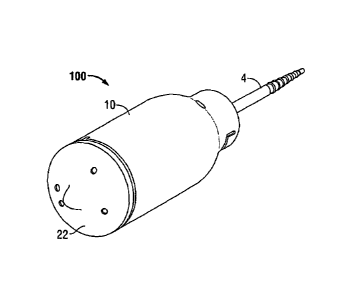
(00111 FIG. 1 is a front perspective view of an end effector in accordance
with an
embodiment of the present disclosure;
100121 FIG. 2 is a rear perspective view of the end effector of FIG. 1;
(00131 FIG. 3 is an exploded perspective view of the end effector shown in
FIG. 1;
4
.rNY, .roo,
CA 02718156 2016-11-15
100141 FIG. 4 is a partial cross-sectional perspective view of the distal
end of the end
effector of FIG. I;
[0015] FIG. 5 is a perspective view of a fastener retaining frame and a
plurality of
fasteners prior to engagement;
[0016] FIG. 6 is an enlarged view of detail area "A" of FIG. 5; and
100171 FIG. 7 is a perspective view of a surgical fastening apparatus
including the end
effector of FIG.1 in accordance with an embodiment of the present disclosure.
DETAILED DESCRIPTION OF THE EMBODIMENTS
[00181 Various embodiments of the presently disclosed end effector will now
be
described in detail with reference to the drawings, wherein like references
numerals identify
similar or identical elements. In the drawings and in the description which
follows, the term
"proximal" will refer to the end of the component that is closer to the
operator during use, while
the term "distal" will refer to the end of the component that is farther from
the operator, as is
traditional and conventional in the art.
100191 With reference to FIGS. 1, 2 and 7, an end effector 100 suitable for
a surgical
fastening apparatus 1000 is illustrated. A suitable example of a surgical
fastening apparatus
1000 is disclosed in U.S. Patent Nos. 7,168,604, 7,303,106 and U.S.
application publication
no. 2010/0089971, filed August 31, 2009. The surgical fastening apparatus 1000
includes a handle
assembly 200, an elongate shaft 300 extending distally therefrom, and an end
effector 100
coupled to the distal end of the elongate shaft 300. The length and the
curvature of elongate
shall 300 may be tailored to meet the specific needs of surgical procedure
being performed.
Elongate shaft 300 alternatively may be flexible to facilitate maneuvering of
surgical fastening
CA 02718156 2010-10-20
apparatus 1000, more specifically, end effector 100, to the targeted area in
the body containing
tissues to be joined.
100201 The handle assembly 200 generally includes a stationary handle 240,
a pivotable
trigger 210 and a rotatable knob 220. When rotatable knob 220 is manually
rotated, anvil
assembly 20 will longitudinally translate in relation to shell assembly 10
between an open
position and a closed position in a manner to be described below. Actuation of
trigger 210
towards stationary handle 240 advances annular pusher 40 (FIG. 3) distally
within shell assembly
to eject fasteners from shell assembly 10 in a manner described below.
Actuation of trigger
210 also longitudinally translates a circular knife 51 that severs tissue as
well as separates the
formed fasteners from a retaining frame in a manner described below.
100211 Referring now to FIGS. 3, and 5 an embodiment of the present
disclosure is
shown generally as staple end effector 100 defining a longitudinal axis "A-A."
Staple end
effector 100 includes an anvil assembly 20 and a shell assembly 10. Anvil
assembly 20 includes
an anvil 22, fastener retaining frame 24, and a flange member 16. Flange
member 16 is
preferably composed of plastic material such as HDPE. As will be discussed in
further detail
below, fastener retaining frame 24 includes a plurality of perforations 26 and
a plurality of
retainers 28 (FIG. 5) and is detachably secured to flange member 16 which is
fixedly attached to
anvil 22. Shell assembly 10 accommodates therein a fastener guide member 30
which includes a
plurality of axially extending and circumferentially arranged fastener slots
34 for receiving
therein a plurality of axially extending surgical fasteners 32 having distally
directed tissue
piercing prongs for mating with the plurality of retainers 28 on fastener
retaining frame 24 to
fasten tissue therebetween. Shell assembly 10 further accommodates therein an
annular pusher
40 including a plurality of pusher fingers 42 operably associated with the
plurality of surgical
6
õ..
CA 02718156 2010-10-20
fasteners 32. Each pusher 42 is configured for ejecting an associated surgical
fastener 32
towards a corresponding retainer 28 on fastener retaining frame 24. A distal
end of drive shaft 4
is operably connected with annular pusher 40 and a proximal end of drive shaft
4 is operably
connected with trigger 210, whereby the actuation of trigger 210 distally
advances drive shaft 4
which advances annular pusher 40 within housing 45 of shell assembly 10 to
eject surgical
fasteners 32 from fastener guide member 30 in a manner to be described below.
A circular knife
51 with an annular cutting blade is advanced by pusher 40 to sever tissue in
the manner
described below.
100221 With particular reference to FIGS. 5 and 6, fastener retaining
frame 24 will be
described in detail. Fastener retaining frame 24 includes a first annular
portion 24a having a
plurality of retainers 28 circumferentially disposed thereon and a second
annular portion 24b
having a plurality of circumferentially arranged perforations 26. The two
annular portions 24a
and 24b are concentrically arranged, with the second annular portion 24b
concentrically arranged
within (radially inward of) the first annular portion 24a. The plurality of
retainers 28 are either
monolithically formed or are individually formed and connected by suitable
structures, e.g.,
links, thereby forming a single body. Moreover, first annular portion 24a may
be monolithically
formed with second annular portion 24b. The first annular portion 24a and the
second annular
portion 24b may be made of different materials; in some embodiments they are
made of
biodegradable polymers (e.g. L4). For clarity, only a few of the retainers,
perforations, etc. are
labeled.
f0023] With reference still to FIGS. 5, and 6 each retainer 28 includes a
bridge 27 and a
pair of posts 29 each forming a cavity or opening 29a therein (note for
clarity only one of the
retainers is labeled in FIG 5). Each retainer 28 is mated with an associated
surgical fastener 32.
7
, , . ..===="-^,===.====
.== ,,,,
CA 02718156 2010-10-20
Specifically, each prong 33 of the associated surgical fastener 32 is inserted
into each cavity 29a
of an associated retainer 28. Surgical fastener 32 and retainer 28 may be
configured to engage in
a snap-fit manner. Furthermore, a tip 33a of each prong 33 may include a barb
34 to enhance
secure mating with retainer 28. Bridge or backspan 35 extends between prongs
33. The plurality
of retainers 28 circumferentially disposed on first annular portion 24a of
fastener retaining frame
24 are arranged to define a ring of retainers 28. The first annular portion
24a in the illustrated
embodiment includes two rings of retainers 28 wherein each ring has 16
retainers, although a
different number of retainers and/or a different number of rings is
contemplated. When more
than one ring of retainers 29 is present in first annular portion 24a,
retainers 28 forming one ring
may be radially aligned with those forming another ring. Alternatively,
retainers 28 forming one
ring may have a partial overlap or be radially offset with those forming
another ring as to allow
uniform integrity of circular stapling. Retainers 28 may be substantially
uniformly spaced apart;
however, the spacing between retainers 28 may be tailored to meet the specific
needs of the
surgical operation being performed. The fasteners 32 and retainers 28 are
preferably made of a
resorbable material.
[00241
With reference still to FIG. 5, fastener retaining frame 24 includes a
plurality of
perforations 26 in second annular portion 24b thereof. The plurality of
perforations 26 may be
substantially uniformly formed (substantially uniformly spaced apart) in
second annular portion
24b. As an alternative to equidistant spacing or substantially equidistant
spacing, other spacings
for the perforations are also contemplated including perforations arbitrarily
defined or otherwise
spaced. In one embodiment, the plurality of perforations 26, like retainers
28, may define more
than one ring of perforations. The diameter of each of the plurality of
perforations 26 may be
selected such that the thickness of the annular blade is less than the
diameter of each of the
8
N=q,
CA 02718156 2010-10-20
perforations 26. Such configuration may facilitate severing or breaking off of
the plurality of
perforations 26. In addition, each perforation 26 may include a radially
notched portion
configured to facilitate severing or breaking off of perforations 26 upon
actuation of annular
pusher 40. Alternatively, each perforation 26 may include a pair of opposing
slits also serving to
facilitate breaking off of perforations 26 upon actuation of annular pusher
40. When employing
perforations 26 containing for example the pair of slits, the width of the
slits may be chosen to
correspond with the thickness of the annular blade to allow the annular blade
to be engaged
within the opposing slits of the associated perforation. In some embodiments,
the thickness of
second annular portion 24b defining the plurality of perforations 26 may be
varied. For example,
an inner part of the second annular portion 24b, i.e., a part that is inside
of the plurality of
perforations 26, can have a thickness less than that of an outer part of
second annular portion
24b, i.e., a part that is in contact with first annular portion 24a, whereby
the relatively thinner
part or a more brittle part can have to facilitate breaking off of
perforations 26 resulting in a
detachment of fastener retaining frame 24 from flange member 16 as will be
discussed below. In
the alternative, the thickness of only a part defining the plurality of
perforations 26 may be less
than that of the rest of second annular portion 24b whereby such configuration
also facilitates
breaking off of the plurality of perforations 26 resulting in a detachment of
fastener retaining
frame 24 from flange member 16.
100251
Turning back to FIG. 4, anvil assembly 20 in a closed position prior to the
firing
of surgical fasteners 32 by the actuation of trigger 210 is illustrated.
Flange member 16 has an
annular recess 18 and includes a ledge 18a to form a supporting/retaining
structure for the
fastener retaining frame 24. Fastener retaining frame 24 is disposed in
annular recess 18 and is
secured therein by ledge 18a. FIG. 4 illustrates ledge 18a securing fastener
retaining frame 24 at
9
CA 02718156 2010-10-20
second annular portion 24b. Accordingly, the thickness of the inner part of
second annular
portion 24b and/or the rigidity of second annular portion 24b may be chosen,
e.g., by choosing
the material having the requisite rigidity, to prevent bending of the mated
fastener retaining
frame 24 at perforations 26 and/or at a location in contact with ledge 18a
prior to severing the
plurality of perforations 26. In one embodiment, a distal side of fastener
retaining frame 24 is
axially tapered with respect to the thickness thereof to enhance secure
attachment thereof to
annular recess 18 of flange member 16 also axially tapered with respect to the
thickness thereof.
Flange member 16 having fastener retaining frame 24 detachably secured thereto
is fixedly
attached to anvil 22 so that fastener retaining frame 24 and anvil 22 move as
a single unit in an
longitudinal translation thereof through a manual operation of the rotational
knob 220 by the
operator.
[00261 Still referring to FIG. 4. shell assembly 10 accommodates fastener
guide member
30 which contains a plurality of circumferentially arranged and axially
extending fastener slots
34 for receiving therein a plurality of axially extending surgical fasteners
32 having tissue
piercing prongs 33 for mating with plurality of retainers 28 on fastener
retaining frame 24 to
fasten body tissue therebetween. FIG. 4 illustrates a surgical fastener 32
loaded in fastener slot
34 and having a proximal side thereof engaged with an associated pusher 42
prior to being fired.
100271 In use, anvil assembly 20 is spaced from shell assembly 10 as shown
in FIG. 7
such that the end effector is an open or unapproximated position. Once the
body tissues to be
fastened are placed in the open space between anvil assembly 20 and shell
assembly 10, anvil
assembly 20 is translated proximally to an approximated position to clamp the
body tissues
therebetween such that the end effector is in a closed or approximated
position. This is achieved
by rotating the rotatable knob 220 of the handle assembly 200.
CA 02718156 2010-10-20
(0028] As shown in FIG. 4, anvil assembly 20 in a pre-fired closed
position is engaged
with shell assembly 10 (see also FIG. 1).
100291 The attachment of fastener retaining frame 24 to flange member 16,
which is
fixedly attached to anvil 22, reduces slippage of fastener retaining frame 24
against anvil 22 and
retains its position with respect to anvil 22 during axial translations
thereof. Once the clamping
of the body tissues has taken place, the operator actuates trigger 210 which
in turn distally drives
the drive shaft 4 connected to annular pusher 40. The plurality of pushers 42
on the distally
translated annular pusher 40 ejects the corresponding set of surgical
fasteners 32 from fastener
slots 34 of fastener guide member 30. Each of the ejected set of surgical
fasteners 32 pierce
through the body tissue and are received into a corresponding retainer 28.
Specifically, a portion
of each of the prongs of fasteners 32 is received into a respective cavity 29a
formed in posts 29
in retainer 28. Note the tip 33 and barbs 34 of fastener prongs 33 deform
receiving walls 29b of
posts 29 as the fastener prong 33 is forced through cavity 29a. The barbs
engage a ledge of the
cavity 29a to prevent retraction (proximal movement) of the fastener 32,
thereby locking the
fastener 32 with the respective retainer 28. Note that since fastener
retaining frame 24 is
securely attached to flange member 16 which is fixedly attached to anvil 22,
slippage of fastener
retaining frame 24 against anvil 22 due to the firing force produced by the
actuation of trigger
210 which ejects the plurality of fasteners 32 from fastener slots 34 into the
body tissues is
reduced. Thus, the position of fastener retaining frame 24 is maintained with
respect to anvil 22
during the firing of surgical fasteners 32. Moreover, the plurality of
retainers 28 are either
monolithically formed or individually formed and connected by suitable
structures, e.g., links,
thereby forming a single body. In either instance, the configuration of the
plurality of retainers
28 as a single body, in conjunction with fastener retaining frame 24 being
secured to flange
11
CA 02718156 2010-10-20
member 16 which is fixedly attached to anvil 22, reduces the radial
misalignment of surgical
fasteners 32 with fastener retaining frame 24.
f00301 As
noted above, fastener retaining frame 24 and fastener guide member 30 may
be configured to provide a plurality of rings of surgical fasteners 32 on
tissues, e.g., two rings of
surgical fasteners wherein each ring is defined by sixteen fasteners, to meet
the needs of the
specific procedure being performed. Upon mating of the plurality of surgical
fasteners 32 with
fastener retaining frame 24, an annular blade 51 is actuated to distally
translate through shell
assembly 10. Note the annular blade can be translatable by actuation of the
trigger 210 which
advances the fasteners, or alternatively by a separate actuator actuated in a
separate step. The
annular blade comes into contact with fastener retaining frame 24 and is
pressed against the
plurality of perforations 26 defined in the fastener retaining frame 24
severing or breaking
perforations 26. The broken or severed perforations 26 enable the mated
surgical fastener 32 and
fastener retaining frame 24 to be detached from anvil 22. The severing or
breaking off of
perforations 26 leaves a residuary ring, i.e., the inner part of second
annular portion 24b of
fastener retaining frame 24, within ledge 18a of annular recess 18 of flange
member 16. In some
embodiments, in order to prevent perforation chips that may be produced during
the severing or
breaking off of perforations 26, each of the plurality of perforations 26 may
be provided with, for
example, a pair of opposing slits or a notched portion, as mentioned above,
wherein the thickness
of the annular blade is chosen to be smaller than, e.g., the width of the pair
of opposing slits. The
mated surgical fastener 32 and fastener retaining frame 24 fastening body
tissue therebetween
would then be free to displace without being restricted or attached to anvil
22. Actuation of the
knife severs the tissue. The operator then moves anvil 22 to the open
(unapproximated) position
by rotating the rotatable knob 220 of the handle assembly thereby distally
translating anvil
12
CA 02718156 2010-10-20
assembly 20. After the removal of the severed tissue, e.g. hemorrhoidal
tissue, the surgical
fastening device is removed from the body.
[00311 From the foregoing and with reference to the various figure
drawings, those
skilled in the art will appreciate that certain modifications can also be made
to the present
disclosure without departing from the scope of the same. For example, the
annular blade may be
fixedly secured to the anvil and configured to break the plurality of
perforations on the fastener
retaining frame upon firing of the plurality of fasteners. Such design
eliminates the need for a
longitudinal translation of the annular blade. Additionally, although
disclosed as annular
portions for use with a circular fastening apparatus, use of linear portions
for use with apparatus
applying linear arrays of fasteners are also contemplated.
100321 While several embodiments of the disclosure have been shown in the
drawings
and/or discussed herein, it is not intended that the disclosure be limited
thereto, as it is intended
that the disclosure be as broad in scope as the art will allow and that the
specification be read
likewise. Therefore, the above description should not be construed as
limiting, but merely as
exemplifications of particular embodiments. Those skilled in the art will
envision other
modifications within the scope and spirit of the claims appended hereto.
13