Note: Descriptions are shown in the official language in which they were submitted.
CA 02718301 2010-10-19
1
ANALYTICAL CHROMATOGRAPHIC METHOD
FIELD OF THE INVENTION
The present invention generally relates to a diaphragm-sealed valve for fluid
analytical systems, and more particularly concerns a diaphragm-sealed valve
having
improved characteristics. The present invention also concerns an analytical
chromatographic system and an analytical chromatographic method using such a
diaphragm-sealed valve.
BACKGROUND OF THE INVENTION
As well known from people involved in the art, chromatographic systems rely
on the use of valves to allow reproducible sample introduction and various
column
switching schemes.
Today, in the chromatographic field, there are mainly two types of valves
used: the rotary valves and the diaphragm-sealed valves. The rotary type, as
the
name suggests, uses a rotary movement to switch or divert various flow paths
required for a particular application. Description of such valves may be found
in US
patent application by the same Applicant published under No. 2006-0042686.
The rotary chromatographic valves are well suited for liquid applications,
even if they are also suitable for gas applications. Their design allows the
use of
various materials to provide inertness or very long lifetime, and relatively
high
working pressure and temperature which can be required in various liquid
chromatography applications. The actuating means used to actuate a rotary
valve is
generally a pneumatic rotary one or an electrical motor equipped with some
gear to
CA 02718301 2010-10-19
, .
2
increase the torque needed to rotate the valve. In both cases, these
assemblies, i.e.
actuating means and valve, require a relatively large amount of room in a
system.
Furthermore, in cases where a pneumatic actuator is used, extra 3-way solenoid
valves must be used to allow pneumatic gas to be switched.
In the bulk gas analysis like He, H2, 02, N2, Ar, Kr, Xe, Ne, CO, 002, CH4,
THC, H20 and some other gases, the working pressure and temperature of the
chromatographic system is relatively low compared to liquid chromatography. A
diaphragm-sealed chromatographic valve could therefore be used since it is
io
generally well suited for gas chromatography. It would so be advisable and
beneficial to use diaphragm-sealed valves instead of rotary valves for gas
chromatography wherein the design of a rotary valve may probably be overkilled
for
low pressure and temperature application in gas chromatography.
A diaphragm-sealed chromatographic valve that would take much less room
than a rotary system and that could be built at a lower cost, mainly when
compared
to rotary valves using ceramic material, while providing a long working
lifetime would
therefore be very desirable.
For the last forty years, many people have designed diaphragm valves for
chromatography. Such diaphragm valves have been used in many commercially
available gas chromatographs. They are able to be integrated more easily in a
gas
chromatograph due to their physical size and since the actuator is embedded in
the
valve itself. These characteristics make them attractive for gas chromatograph
manufacturers. However, their performances are poor. For example, the leak
rate
from port to port is too high and thus limits the system performance.
Moreover, the
pressure drop on the valve's ports differs from port to port, causing pressure
and
flow variation in the system. This causes detrimental effect on column
performance
and detector baseline. Furthermore, many of them have too much inboard
CA 02718301 2010-10-19
3
contamination. Such valve designs are shown in US patents Nos. 3,111,849;
3,140,615; 3,198,018; 3,376,894; 3,387,496; 3,417,605; 3,439,542; 3,492,873;
3,545,491; 3,633,426; 4,112,766; 4,276,907; 4,333,500; 5,601,115 and
6,202,698.
The general concept of these valves is shown in Figure 1.
As illustrated in Figure 1, the valve 1 is provided with a top block 2 having
an
interface 4 and a plurality of ports 6. Each of the ports 6 opens at the
interface 4 and
has an inclined thread passage 8 to connect various analytical fitting and
tubing (not
shown). At the bottom of the inclined thread passage 8, there is a conduit 10
extending in the top block 2 and opening at the interface 4. The ports 6 are
arranged
on a circular line on the interface 4 of the top block 2. The interface 4 is
advantageously flat and polished to minimize leaks between port and from
ambient
atmosphere. The valve 1 is also provided with a bottom block 12 and a
diaphragm
14, which is generally made of polyimide, Teflon TM or other polymer material.
The
diaphragm 14 is positioned between the top block interface 4 and the bottom
block
12. The valve 1 is also provided with a plurality of plungers 16, each being
respectively arranged to be able to compress the diaphragm 14 against the top
block 2 at a position located between two of the ports 6. Preferably, as
illustrated,
when the valve is at rest, three plungers 16 are up while the three others are
down.
When the plungers are up, they compress the diaphragm 14 against the top block
2
for closing the conduits made by diaphragm recess 18, so that fluid
circulation is
blocked. Alternatively, there is fluid flowing between the ports where the
corresponding plungers are down. The recess 18 in the diaphragm 14 sits down
in
the recess 20 made in the bottom block 12, thereby allowing some clearance for
fluid circulation. The bottom block 12 keeps the plungers 16 and the actuating
mechanism in position.
Referring now to Figure 2A, there is shown a typical chromatographic
application wherein a sample is injected on a separation column to separate
the
CA 02718301 2010-10-19
4
impurities and then to measure them by the integration of successive signal
peaks
by the detector, as well known in the art. In Figure 2A, the sample loop SL is
swept
by the sample gas, while the separation column and the detector are swept by
the
carrier gas, coming from the valve port #2. To allow this flow path through
the valve,
the plungers B, D and F are down while the plungers A, C and E are up. The
mechanical equivalent of this valve position is shown in Figure 2B. To do a
sample
injection, all valve ports must first be isolated from each other to avoid
cross port
leaks that invariably lead to inaccurate measurements. This is done by setting
plungers B, D and F in the up position. The valve analytical flow path and
mechanical equivalent of this valve position is shown in Figure 3A and 3B.
This step
is only a temporary intermediate one. Its time duration depends on the
actuating
mechanism used and the required actuating pneumatic pressure. Then, the sample
loop is put in the carrier circuit. This step is generally known as the
sampling loop
injection position. This is done by moving down plungers A, C and E while
keeping
plungers B, D and F in the up position. This position is shown on Figure 4A
and the
mechanical one in Figure 4B. In a similar way, to come back in the sampling
position which is illustrated in Figure 2A, the plungers A, C and E are first
brought
back in the up position. This leads to the intermediate position shown in
Figure 3A,
i.e. all plungers up. Finally, the plungers B, D and F are brought back down.
So, the
valve is now in the position shown in Figure 2A, i.e. sampling loop filling
position. All
the patents that we previously referred use this general concept or some
slight
variation thereof.
Referring again to Figure 1, the main aspect of this concept is to interrupt
the
flow between two adjacent ports. For that, the corresponding plunger presses
the
diaphragm 14, which is then pressed on the interface 4 of the top block 2.
Thus, the
sealing relies simply on the surface of the plunger defining the area that
presses the
diaphragm recess 18 on the interface 4. This technique imposes tight
tolerances on
the surface finish, surface flatness and the plungers' length. Any scratch on
the
CA 02718301 2010-10-19
interface 4 or imperfection of the diaphragm 14 will generate leaks. Moreover,
the
length of all plungers must be the same. Any difference in their lengths will
result in
leaks, since a shorter plunger will not properly compress the diaphragm
against the
interface 4. In the prior art, there are some variations of this general
concept. The
5 main one relates to the location of the bottom block recess 20. In the
past, this
recess 20 or its equivalent was located internally in the top block 2, or on
its
interface 4. US patents Nos. 3,111,849; 3,198,018; 3,545,491; 3,633,426 and
4,112,766, which were granted to the same group of people, illustrate this
concept.
However, as they reported in a more recent valve brochure specification
entitled
"Applied Automation Company, series 11 diaphragm valve", this method has been
dropped because of a too high cold flow. Cold flow is also often referred to
as cross
port flow leak. Their latest design, which was commercialized, uses a flat and
polished interface 4 on the top block 2 and a recess 20 in the bottom block
12. In
this design, the diaphragm 14 has no recess. Moreover, in order to reduce the
cold
flow, it was also envisaged to use two diaphragms. In fact, as disclosed in US
patent
No. 3,111,849, the use of a "cushion" diaphragm helps to compensate for any
slight
non-parallelism or length difference of plungers. Other attempts have also
been
made to correct the non-parallelism, as disclosed in US patents Nos.
3,376,894;
3,545,491 and 3,633,426, wherein the use of solid plungers has been replaced
with
the use of small steel balls.
The concern about plunger length has also been taken into consideration in
US patent No. 6,202,698, granted to Valco Company, which suggests the use of
plungers made of softer material. This allows tolerance reduction for the
length of
such plungers.
However, such designs still result into too much leak rate between ports
since the sealing done by the plungers' pressure is not equal on diaphragm.
CA 02718301 2010-10-19
6
Other attempts have been made in the past to eliminate problems caused by
plunger tolerance variations. US patent No. 3,139,755 discloses a valve
wherein no
plunger is used. Instead, a hydraulic pressure is used. However, an auxiliary
source
of pressure must be used since the pneumatic amplification of pneumatic
actuating
mechanism does not exist. The system, as far as we know, wasn't
commercialized.
Cross port leaks are still an important problem.
Another design is disclosed in US patent No. 3,085,440. In this valve, the
diaphragm has been replaced by an 0-ring. Nevertheless, cross port leaks are
still
too high for modern high sensitivity detector.
In brief, in view of the previously mentioned patents, it can be seen that
many
attempts have been made to try fixing cross port leaks problems and outboard
or
inboard contamination. All of the proposed designs are quite similar in regard
to
sealing mechanisms and have the same drawbacks. For example, US patent No.
3,140,615, granted in 1964, and US patent No. 6,202,698, granted in 2001, do
use
the same sealing concept in regard to flow switching between ports.
Valco Company did release the DV series valve wherein the diaphragm 14
has an additional recess 18 as illustrated in Figure 1. The recess 18 sits
down in the
recess 20 of the bottom block 12. So, when a plunger 16 is in down position,
the
diaphragm recess 18 sits in the bottom block recess 20, thereby clearing the
passage between two adjacent ports, reducing the pressure drop and helping to
operate with a low pressure sample.
Finally, it can be seen from the various brochures used to market these
valves that the lifetime of these valves is mostly stated in terms of
actuations. Most
of the time, the number of actuations stated is between 500,000 and 1,000,000.
However, it appears that this specification is related to the actuating
mechanism and
CA 02718301 2010-10-19
7
not to the leak rate of the valve. In this aspect, the diaphragm type valve's
specifications are not as well defined as the rotary type valve, wherein it is
clear that
the lifetime of the valve is expressed in terms of leaks.
Besides, a brand new diaphragm valve will often have too many leaks
between ports for low level applications. Moreover, it appears that when the
valve is
at rest for a long period of time, it doesn't perform well when put back in
service.
This is caused by the diaphragm getting compressed and marked where the
plungers press it. It is even worst for valves having fine edge plungers
defining a
ring type sealing surface.
Thus, the diaphragm type gas chromatography valves of the prior art have
several disadvantages: they present too much cross port leaks and too much
pressure drop on selected adjacent ports. Moreover, they are difficult to
operate
when sample pressure is low and they cannot conveniently work with sub-
atmospheric sample pressure. Furthermore, they rely on tight tolerance of
plungers'
length, to minimize cross port leaks.
Therefore, it would be desirable to provide a diaphragm-sealed valve that
would overcome the above-mentioned drawbacks of the diaphragm valves of the
prior art while being less expensive to manufacture.
SUMMARY OF THE INVENTION
An object of the present invention is to provide a diaphragm-sealed valve that
satisfies the above-mentioned needs.
Accordingly, the present invention provides a diaphragm-sealed valve
comprising a first body having a first interface. The first interface is
provided with a
CA 02718301 2010-10-19
8
recessed fluid communication channel extending therein. The first body has a
first, a
second and a common fluid port. Each of the ports opens into the recessed
fluid
communication channel for interconnecting each of the ports together through
the
fluid communication channel. Each of the first and second ports is provided
with a
seat disposed so as to allow fluid communication therearound within the
communication channel. The diaphragm-sealed valve is also provided with a
second
body interconnected with the first body and having a second interface facing
the first
interface. The second body has a first and a second passage, each of the
passages
facing one of the first and second ports respectively. The diaphragm-sealed
valve is
io also provided with a seal member compressibly positioned between the
first and
second interfaces. The seal member has a shape adapted to cover the first and
second ports. The diaphragm-sealed valve is also provided with a first and a
second
plunger, each being respectively slidably disposed in one of the passages of
the
second body. Each of the plungers has a closed position wherein the
corresponding
plunger presses down the seal member against the seat of the corresponding
port
for closing the corresponding port, and an open position wherein the plunger
extends away from the seat of the corresponding port for allowing a fluid
communication between the corresponding port and the channel. The diaphragm-
sealed valve is also provided with actuating means for actuating each of the
plungers between the closed and open positions thereof.
In a preferred embodiment of the present invention, the actuating means
independently actuate each of the plungers.
According to another aspect of the invention, there is also provided an
analytical chromatographic system having a diaphragm-sealed valve as defined
above and further having a purge circulation line. The purge circulation line
comprises an annular recess extending in the first interface and surrounding
the
fluid communication channel. The purge circulation line also has a fluid inlet
and a
CA 02718301 2010-10-19
9
fluid outlet, each having an opening lying in the annular recess for providing
a
continuous fluid flow in the annular recess. The analytical chromatographic
system
is also provided with monitoring means operatively connected to the fluid
outlet for
monitoring a fluid passing therethrough.
In a preferred embodiment of the analytical chromatographic system, the
monitoring means are adapted to monitor the fluid continuously.
In a further preferred embodiment of the present invention, there is also
provided another diaphragm-sealed valve comprising a first body having a first
interface. The first interface is provided with a plurality of distinct
recessed fluid
communication channels extending therein. The first body has a plurality of
port
sets, each comprising a first, a second and a common fluid port. Each port of
a
corresponding set opens into a corresponding one of the recessed fluid
communication channels respectively for interconnecting each port of the
corresponding set together through the corresponding fluid communication
channel
respectively. Each of the first and second ports of each of the sets is
provided with a
seat disposed so as to allow fluid communication therearound within the
corresponding communication channel. The diaphragm-sealed valve is also
provided with a second body interconnected with the first body and having a
second
interface facing the first interface. The second body has a plurality of
passage pairs,
each comprising a first and a second passage. Each passage of a corresponding
pair respectively faces one of the first and second ports of a corresponding
set. The
diaphragm-sealed valve is also provided with a seal member compressibly
positioned between the first and second interfaces. The seal member has a
shape
adapted to cover each of the first and second ports of all of the port sets.
The
diaphragm-sealed valve is also provided with a plurality of pairs of first and
second
plungers, each plunger of a corresponding pair being respectively slidably
disposed
in one of the passages of a corresponding pair. Each of the plungers has a
closed
CA 02718301 2013-06-20
. .
position wherein the corresponding plunger presses down the seal member
against
the seat of the corresponding port for closing the corresponding port, and an
open
position wherein the plunger extends away from the seat of the corresponding
port
for allowing a fluid communication between the corresponding port and a
5 corresponding channel. The diaphragm-sealed valve also has actuating
means for
actuating each of the plungers between the closed and open positions thereof.
According to another aspect of the invention, there is also provided an
analytical
chromatographic method using a fluid sampling system comprising a diaphragm-
10 sealed valve provided with a plurality of independently actuated ports
serially
interconnected to each other, said fluid sampling system further comprising a
sample inlet, a carrier inlet, a sampling loop having an inlet and an outlet,
a sample
vent line and analytical means provided with an inlet, each being operatively
interconnected to said valve through a corresponding one of said ports, the
method
comprising the steps of, successively:
a) providing fluid communication from said sample inlet to the inlet of the
sampling loop by actuating the corresponding ports, thereby providing a fluid
sample in said sampling loop;
b) closing the outlet of said sampling loop by actuating the corresponding
port
to isolate said sampling loop;
c) providing fluid communication from the carrier inlet to the inlet of the
sampling loop by actuating the corresponding port while keeping the outlet of
the
sampling loop closed, to pressurize said sampling loop;
d) preventing fluid communication from each of said ports to the remaining
ports by actuating the corresponding ports; and
e) providing fluid communication from the outlet of the sampling loop to the
inlet of the analytical means by actuating the corresponding port, thereby
injecting
said sample in said analytical means.
CA 02718301 2010-10-19
11
BRIEF DESCRIPTION OF THE DRAWINGS
These and other objects and advantages of the invention will become
apparent upon reading the detailed description and upon referring to the
drawings in
which :
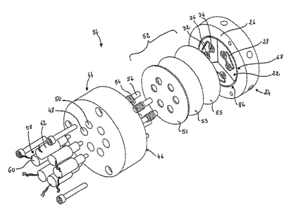
FIGURE 1 (PRIOR ART) is an exploded perspective view of a diaphragm-
sealed valve known in the art.
FIGURE 2A (PRIOR ART) is a schematic representation of a prior typical
chromatographic application using a six-port valve, the valve being in a
sampling
position.
FIGURE 2B (PRIOR ART) is an exploded perspective view of the
diaphragm-sealed valve shown in FIGURE 2A.
FIGURE 3A (PRIOR ART) is a schematic representation of the valve shown
in FIGURE 2A, the valve being in an intermediate position.
FIGURE 3B (PRIOR ART) is an exploded perspective view of the valve
shown in FIGURE 3A.
FIGURE 4A (PRIOR ART) is a schematic representation of the valve of
FIGURE 2A, the valve being in a sample injection position.
FIGURE 4B (PRIOR ART) is an exploded perspective view of the valve
shown in FIGURE 4A.
FIGURE 5A is a top view of a preferred embodiment of the first body of a
CA 02718301 2010-10-19
12
diaphragm-sealed valve of the present invention.
FIGURE 5B is a cross-sectional side view taken along line A-A of the
diaphragm-sealed valve shown in FIGURE 5A.
FIGURE 6A is a top view of a port of the valve shown in FIGURE 5B, the port
being in an open position.
FIGURE 6B is a cross-sectional side view of the port shown in FIGURE 6A.
FIGURE 6C is a top view of the port shown in FIGURE 6A, the port being in a
closed position.
FIGURE 6D is a cross-sectional view of the port shown in FIGURE 6C.
FIGURE 7A is a top view of the first body shown in FIGURE 5A, the ports
being in a predetermined position.
FIGURE 7B is a schematic representation of the ports shown in FIGURE 7A.
FIGURE 7C is a top view of the first body shown in FIGURE 5A, the ports
being in another position.
FIGURE 7D is a schematic representation of the ports shown in FIGURE 7C.
FIGURE 7E is a top view of the first body shown in FIGURE 5A, the ports
being in another position.
FIGURE 7F is a schematic representation of the ports shown in FIGURE 7E.
CA 02718301 2010-10-19
13
FIGURE 7G is a top view of the first body shown in FIGURE 5A, the ports
being in another position.
FIGURE 7H is a schematic representation of the ports shown in FIGURE 7G.
FIGURE 8 is a top view of another preferred embodiment of the first body of
a diaphragm-sealed valve of the present invention.
FIGURE 9A is a schematic representation of a typical chromatographic
application using the valve of the present invention shown in FIGURE 5, the
valve
being in the sampling position.
FIGURE 9B is a schematic representation of the chromatographic application
illustrated in FIGURE 9A, the valve being in the intermediate position.
FIGURE 90 is a schematic representation of the chromatographic application
illustrated in FIGURE 9A, the valve being in the sample injection position.
FIGURE 10A is an exploded perspective view of a diaphragm-sealed valve,
according to another preferred embodiment of the present invention.
FIGURE 10B is a schematic representation of the valve shown in FIGURE
10A, the valve being in the sampling position.
FIGURE 100 is an exploded perspective view of the valve shown in FIGURE
1 OB.
FIGURE 10D is a schematic representation of the valve shown in FIGURE
CA 02718301 2010-10-19
14
1 OA, the valve being in the intermediate position.
FIGURE 10E is an exploded perspective view of the valve shown in FIGURE
10D.
FIGURE 1OF is a schematic representation of the valve shown in FIGURE
10A, the valve being in the sample injection position.
FIGURE 10G is an exploded perspective view of the valve shown in FIGURE
10F.
FIGURE 11 is a schematic representation of an analytical chromatographic
method, according to a preferred embodiment of the present invention.
FIGURE 12A illustrates a conventional baseline generated by a prior art
valve.
FIGURE 12B illustrates a baseline generated by a preferred embodiment of
the valve of the present invention.
FIGURE 13 (PRIOR ART) is a schematic representation of another typical
chromatographic application known in the art, the configuration using two six-
port
valves of the prior art.
FIGURE 14A is a schematic representation of the chromatographic
application shown in FIGURE 13, the configuration using a diaphragm-sealed
valve
of the present invention, the valve being in the sampling position.
FIGURE 14B is a schematic representation of the chromatographic
CA 02718301 2010-10-19
application shown in FIGURE 14A, the valve being in the sample injection
position.
FIGURE 14C is schematic representation of the chromatographic application
shown in FIGURE 14A, the valve being in the heartcut position.
FIGURE 15A is another schematic representation of the chromatographic
application shown in FIGURE 14A.
FIGURE 15B is another schematic representation of the chromatographic
10 application shown in FIGURE 14B.
FIGURE 150 is another schematic representation of the chromatographic
application shown in FIGURE 14C.
15 FIGURE 16A is a schematic representation of another preferred
embodiment
of the diaphragm-sealed valve of the present invention, the valve being in the
sampling position.
FIGURE 16B is a schematic representation of the valve shown in FIGURE
16A, the valve being in the intermediate position.
FIGURE 160 is a schematic representation of the valve shown in FIGURE
16A, the valve being in the sample injection position.
FIGURE 16D is a schematic representation of another preferred embodiment
of the diaphragm-sealed valve of the present invention.
FIGURE 17 is an exploded perspective view of the diaphragm-sealed valve
shown in FIGURE 16D.
CA 02718301 2010-10-19
16
FIGURE 18 is an exploded perspective view of another preferred
embodiment of the diaphragm-sealed valve of the present invention.
FIGURE 19A is a partial cross-sectional side view of the valve shown in
FIGURE 18, the valve being in the sampling position.
FIGURE 19B is a partial cross-sectional side view of the valve shown in
FIGURE 18, the valve being in the intermediate position.
FIGURE 190 is a partial cross-sectional side view of the valve shown in
FIGURE 18, the valve being in the sample injection position.
FIGURE 20A is an exploded perspective view of another preferred
embodiment of the diaphragm-sealed valve of the present invention.
FIGURE 20B is a cross sectional view of the valve actuator shown in
FIGURE 20A.
While the invention will be described in conjunction with example
embodiments, it will be understood that it is not intended to limit the scope
of the
invention to such embodiments. On the contrary, it is intended to cover all
alternatives, modifications and equivalents as may be included as defined by
the
appended claims.
DESCRIPTION OF PREFERRED EMBODIMENTS
In the following description, similar features in the drawings have been given
similar reference numerals and, in order to weight down the figures, some
elements
CA 02718301 2010-10-19
q ,
,
17
are not referred to in some figures if they were already identified in a
precedent
figure.
The present invention concerns a diaphragm-sealed valve, also referred to as
s a diaphragm based tight shut off valve, mostly dedicated for analytical
equipments,
and more particularly chromatographic equipments or on line analyzers. The
present invention also concerns chromatographic systems and chromatographic
methods based on the use of at least one diaphragm-sealed valve. As will be
greater detailed herein below, these systems and methods are based on the use
of
io at least one diaphragm-sealed valve, which, in a first preferred
embodiment can be
referred to as a three way switching cell. This switching cell has one common
port
and two actuated ports, these actuated ports being advantageously
independently
actuated. Thus, each of the independently actuated ports is preferably
independently controlled in a way that both could be open or closed at the
same
15 time or one could be open while the other is closed and vice versa.
Moreover, the
fluid flowing through the common port could be allowed to flow to or from any
one of
the independently actuated ports at the same time or in a predetermined
sequence.
In preferred embodiments of the present invention which will be described
20 below, a plurality of three way switching cells are advantageously used
to allow
more complex flow path switching schemes. By interconnecting together various
switching cells, a typical chromatographic diaphragm valve could be done. In
the
case an elementary cell is used, the switching steps could be: make before
break,
break before make, all ports opened or all ports closed. These switching steps
are
25 not available with standard three way valves.
Referring to Figures 5A and 5B, there is shown a first preferred embodiment of
the present diaphragm-sealed valve, which can be referred to as a three way
switching cell. The illustrated diaphragm-sealed valve 22 is provided with a
first
CA 02718301 2010-10-19
,
18
body 24 having a first interface 26 provided with a recessed fluid
communication
channel 28 extending therein. The recessed fluid communication channel 28
preferably has a loop shaped portion 30. The first body 24 has a first, a
second and
a common fluid port, respectively 32, 34 and 36. As known in the art, each of
the
s ports is preferably provided with a fluid passage 38 connected to a
threaded hole 40
providing tubing connections. Each of the ports 32, 34, 36 opens into the
recessed
fluid communication channel 28 for interconnecting each of the ports together
through the fluid communication channel 28, which acts as a fluid conduct.
Each of
the first and second ports 32, 34 is provided with a seat 42 disposed so as to
allow
fluid communication therearound within the communication channel 28.
Preferably,
and as illustrated, the seat 42 of each of the first and second ports 32, 34
has a
raised portion, which can preferably extend at the interface level 26. More
preferably, the raised portions of the seats 42 of the ports 32, 34 are lower
than the
interface 26 to give room for the seal member 52 vertical movement, as will be
greater detailed below. The diaphragm-sealed valve 22 is also provided with a
second body 44 interconnected with the first body 24, preferably by any
convenient
attaching means known in the art such as a set of screws (not shown). The
second
body 44 has a second interface 46 facing the first interface 26. The second
body 44
also has a first and a second passage 48, 50. Each of the passages 48, 50
faces
one of the first and second ports 32, 34 respectively. The valve 22 is also
provided
with a seal member 52 compressibly positioned between the first and second
interfaces 26, 46. The seal member 52 has a shape adapted to cover the first
and
second ports 32, 34, and advantageously the entire fluid communication channel
28
to act as a seal for inboard or outboard contaminations. This seal member 52
allows
to provide a flow interruption through the corresponding port 32 or 34, when
it is
pressed against the seat 42 of the port. Preferably, the seal member 52 has a
polymer diaphragm 55 and each of the first and second interfaces 26, 46 has a
planar and circular shape. More preferably, the seal member 52 has a TeflonTm
spacer 51, a metallic diaphragm 53 which is advantageously a stainless
diaphragm,
CA 02718301 2010-10-19
19
and a polymer diaphragm 55. Each of these elements is advantageously arranged
in a stacked relationship, the polymer diaphragm 55 being pressable against
the
seat 42 of each of the first and second ports 32, 34. The valve 22 is also
provided
with a first and a second plunger 54, 56, each being respectively slidably
disposed
in one of the passages 48, 50 of the second body 44. Each of the plungers 54,
56
has a closed position wherein the corresponding plunger presses down the seal
member 52 against the seat 42 of the corresponding port 32, 34 for closing the
corresponding port, and an open position wherein the plunger extends away from
the seat 42 of the corresponding port 32, 34 for allowing a fluid
communication
between the corresponding port and the channel 28. In this preferred
embodiment,
the Teflon spacer is advantageously provided with a first and a second hole,
each
for respectively slidably receiving one of the plungers 54, 56. The valve 22
also has
actuating means 58 for actuating each of the plungers 54, 56 between the
closed
and open positions thereof. Preferably, the actuating means 58 independently
actuate each of the plungers 54, 56. More preferably, the actuating means 58
advantageously have a first and a second solenoid 60, 62, each respectively
actuating one of the first and the second plungers 54, 56. Nevertheless, it
should be
noted that any other actuating means that advantageously allow an independent
actuation of the plungers 54, 56 could also be envisaged as will be greater
detailed
thereinafter. Preferably, and as illustrated, the actuating means 58
advantageously
have first and second resilient means, preferably a first and a second spring
64, 66,
each being respectively mounted on a corresponding plunger 54, 56 for biasing
the
corresponding plunger. Each of the spring 64, 66 can advantageously be mounted
in two different positions, thereby providing a predetermined resting position
for
each of the plungers 54, 56. Thus, different valve configurations can
advantageously be obtained at power off. Both plungers 54, 56 can be forced up
or
down. In the illustrated preferred embodiment, the spring 64 associated with
the
solenoid 60 is mounted to force the plunger 54 down while the spring 66
associated
to the solenoid 62 is mounted to force the plunger 56 up. This results in a
CA 02718301 2010-10-19
configuration normally closed (NC) between port 32 and 36, and normally open
(NO) between port 34 and 36, when there is no power on the solenoids 60 and
62.
Referring now to Figures 6A to 6D, there is illustrated the working principle
of
5 one of the first and second ports 32, 34. In Figures 6A and 6B the port
32 is open,
so the fluid is allowed to flow through port 32 and then in each direction
away from
the seat 42. Of course, according to a particular application, the fluid could
flow from
or to the port 32. In Figures 6C and 6D, the port 32 is shown in the closed
position.
The fluid from the other ports is allowed to flow around the seat 42 in the
fluid
10 communication channel 28.
Figures 7A to 7H illustrate the different fluid flow paths and the schematic
equivalents which can be obtained with the present valve. Figures 7A and 7B
show
the port 32 in the open position while port 34 is in the closed position.
Figures 7C
15 and 7D show the port 32 closed while the port 34 is opened. Figures 7E and
7F
show both ports 32, 34 open while Figures 7G and 7H show both ports 32, 34
closed.
An important characteristic of the invention can be deducted from Figures 6
20 and 7. In anyone valve positions, there is no dead volume since there is
always fluid
flowing around the seat 42 and in the loop shaped portion 30 of the fluid
communication channel 28. So there is no dead volume effect generated by the
valve since the channel 28 always appears like a fluid conduit or tubing.
Another important aspect of the present invention is the independent control
of the ports 32 and 34. This allows the different valve positions shown in
Figures 7A
to 7H. Moreover, the valve timing between actuation steps can be easily
controlled
by a control means (not shown) operatively connected to the actuating means
58.
For example, when switching from port 32 to 34, the actuation step could be
make
CA 02718301 2013-06-20
. .
21
before break or break before make.
The fact of sealing the ports 32 and 34 by pressing the diaphragm 52 thereon
results in a positive sealing effect. Indeed, it seals completely the port 32
or 34 and
totally blocks the fluid flow therefrom or thereinto. So, relatively high
pressure could
be applied to the ports 32, 34 without generating any leak nor any detrimental
impact on the analytical results.
Moreover, in a preferred embodiment, the plungers 54, 56 can
1 o
advantageously be tied to the diaphragm 52. Thus, when the plunger 54 or 56 is
in
the open position, it pulls up the diaphragm 52 from the port 32 or 34. This
has for
effect of clearing completely the corresponding port seat 42. So, there is
very little
pressure drop on the port and the pressure is similar for any of the ports 32,
34.
Furthermore, the valve of the present invention advantageously allows sub
atmospheric pressure operation. Indeed, Figure 8 shows another preferred
embodiment of the present invention, wherein the valve 22 further has a purge
circulation line 68. The purge circulation line 68 is provided with an annular
recess
70 extending in the first interface 26 and surrounding the fluid communication
channel 28. The purge circulation 68 line also has a fluid inlet 72 and a
fluid outlet
74, each having an opening lying in the annular recess 70 for providing a
continuous fluid flow in the annular recess 70. Preferably, the fluid inlet
and outlet
72, 74 are each provided with a fluid passage 76 and an associated threaded
hole
78 for allowing tubing connections. Thus, a clean purging fluid can
advantageously
be allowed to flow through the purge circulation line 68, thereby evacuating
any
inboard and outboard contamination and any fluid process leak. This concept is
detailed in the above mentioned US patent application published under
No. US 2006/0042686.
CA 02718301 2010-10-19
.=
22
Still referring to Figure 8, the valve of the present invention can also
advantageously be used in an analytical chromatographic system 80 to provide a
system having improved characteristics. Indeed, such an analytical
chromatographic
system 80 is advantageously provided with a diaphragm-sealed valve 22 as
defined
above and provided with a purge circulation line 68. The analytical system 80
is also
advantageously provided with monitoring means 82 operatively connected to the
fluid outlet 74 for monitoring a fluid passing therethrough. In a preferred
embodiment, the monitoring means 82 have a purity detector for detecting
contamination of said fluid. Preferably, the monitoring means 82 are adapted
to
monitor the fluid passing through the purge circulation line 68 continuously.
As already explained, as a first application, the valve could be used as a
simple three way type switching valve used to switch between two streams.
However, an interesting aspect of the present invention is revealed when we
combine together a plurality of elementary switching cells 22 as previously
described.
Accordingly, referring now to Figures 10A to 10G, there is shown another
diaphragm sealed valve according to another preferred embodiment of the
present
invention which uses a plurality of elementary switching cells 22. Indeed, in
this
preferred embodiment, the diaphragm-sealed valve 84 is provided with a first
body
24 having a first interface 26 provided with a plurality of distinct recessed
fluid
communication channels 28 extending therein. The first body 24 has a plurality
of
port sets, each comprising a first, a second and a common fluid port 32, 34,
36.
Each port of a corresponding set opens into a corresponding one of the
recessed
fluid communication channels 28 respectively for interconnecting each port 32,
34,
36 of the corresponding set together through the corresponding fluid
communication
channel 28 respectively. Each of the first and second ports 32, 34 of each of
the
sets is provided with a seat 42 disposed so as to allow fluid communication
CA 02718301 2010-10-19
23
therearound within the corresponding communication channel 28. As already
explained with reference to FIGURES 5A and 5B, each of the seats 42 of the
first
and second ports 32, 34 is preferably lower than the interface 26 for giving
sufficient
room for the seal member vertical movement. The diaphragm sealed valve 84 is .
also provided with a second body 44 interconnected with the first body 24 and
having a second interface 46 facing the first interface 26. The second body 44
has a
plurality of passage pairs, each comprising a first and a second passage 48,
50.
Each passage 48, 50 of a corresponding pair respectively faces one of the
first and
second ports 32, 34 of a corresponding set. The diaphragm sealed valve 84 is
also
provided with a seal member 52 compressibly positioned between the first and
second interfaces 26, 46. The seal member 52 has a shape adapted to cover each
of the first and second ports 32, 34 of all of the port sets. Preferably, the
sealed
member 52 has a polymer disc 55. More preferably, as previously described with
reference to Figures 5A and 5B the seal member 52 has a Teflon spacer 51, a
metallic diaphragm 53 which is advantageously a stainless diaphragm, and a
polymer diaphragm 55. Each of these elements is advantageously arranged in a
stacked relationship, the polymer diaphragm 55 being pressable against the
seat 42
of each of the first and second ports 32, 34. The diaphragm sealed valve 84 is
also
provided with a plurality of pairs of first and second plungers 54, 56. Each
plunger
54, 56 of a corresponding pair is respectively slidably disposed in one of the
passages 48, 50 of a corresponding pair. Each of the plungers 54, 56 has a
closed
position wherein the corresponding plunger presses down the seal member 52
against the seat 42 of the corresponding port 32, 34 for closing the
corresponding
port, and an open position wherein the plunger extends away from the seat 42
of the
corresponding port 32, 34 for allowing a fluid communication between the
corresponding port and a corresponding channel 28. The diaphragm sealed valve
84 also has actuating means 58 for actuating each of the plungers 54, 56
between
the closed and open positions thereof. Preferably, the actuating means 58
independently actuate each of the plungers 54, 56, as already described above.
CA 02718301 2010-10-19
s. =
24
Still referring to Figures 10A to 10G, in a further preferred embodiment, the
valve is further advantageously provided with a purge circulation line 68. The
purge
circulation line 68 has a looped recessed fluid circuit 86 extending in the
first
interface 26. The looped fluid circuit 86 has an outer annular recess 88 and
an inner
recess 90, each extending in the first interface 26. The fluid circuit 86
further has a
plurality of separation recesses 92 radially extending in the first interface
26. Each of
the separation recesses 92 is connected to each of the outer and inner
recesses 88,
90 for defining a plurality of first interface portions 94 isolated from each
others.
lo Each of the first interface portions 94 encloses one of the fluid
communication
channels 28. The fluid circuit 86 is also provided with a fluid inlet 72 and a
fluid
outlet 74, each having an opening lying at the first interface 26. Each of the
inlet and
outlet 72, 74 is in continuous fluid communication with a respective one of
the outer
and inner recesses 88, 90 for providing a continuous fluid flow in the looped
recessed fluid circuit 86. This preferred embodiment is particularly
advantageous
since it allows to continuously monitor the working of the valve for detecting
any
undesirable contamination and/or leaks. In another further preferred
embodiment,
as illustrated, each of the first and second ports 32, 34 is advantageously
circularly
arranged in a port circle 96 concentrical with the first interface 26. In
another further
preferred embodiment, the actuating means 58 advantageously have a plurality
of
pairs of first and second solenoids 60, 62, each solenoid of a corresponding
pair
respectively actuating a corresponding one plunger 54, 56 of a corresponding
pair.
With the different valve configurations described above, different
applications can be
envisaged.
Referring again to Figure 2A, there is shown a typical chromatographic
application known in the art, which uses a six port traditional gas
chromatographic
valve. When the valve is actuated, the sample is injected or put into the
carrier
circuit as shown in figure 4A. Figures 9A to 9C show schematic representations
of
CA 02718301 2010-10-19
the different steps which could be realized with the application illustrated
in Figure
2A but realized with the valve 84 of the present invention. In this preferred
embodiment of the invention, the valve 84 is provided with three elementary
switching cells 22. Each switching cell 22 is represented by a rectangular box
with
s three small circles identifying the ports. The letter c in the
rectangular box identifies
the common port 36. Figure 9A shows the valve 84 at power off. This position
is the
sampling one like shown in figure 2A. Figure 9B shows the intermediate
position
wherein all ports 32, 34 are closed to prevent port flow mixing, like in
Figure 3A.
Finally, Figure 9C shows the sample injection position, like in Figure 4A.
Figures 10A to 10G illustrate the valve 84 of the present invention in
different
positions. Figures 10B and 100 show the sampling mode position, Figures 10D
and
10E show the intermediate position wherein all ports 32, 34 are closed, while
Figures 1OF and 10G show the sample injection position. So, one can see that
the
three elementary switching cells 22 are simply embedded in the same substrate.
As
described above, in this illustrated preferred embodiment, there is an outer
annular
recess 88 surrounding all of the cells 22, and separation recesses 92 for
isolating
each of the cells 22. Thus, a purging fluid can advantageously be introduced
into the
fluid inlet 72, preferably extending in the inner recess 90, where the
separation
recesses 92 join together. This purging fluid can thus flow through the
separation
recesses 92 between the cells 22, and then to the outer annular recess 88 and
then
exit by the fluid outlet 74, preferably extending therein. Of course, the
fluid inlet 72
could extend in the outer recess 88 while the fluid outlet 74 could extend in
the inner
recess 90. So any leak that may occur over the time from anyone of the cells
22 will
reach the purge circulation line 68 first, avoiding contaminating the other
cells.
Indeed, with reference to Figure 10B, the valve 84 can advantageously be used
in
an analytical chromatographic system 126 to provide a system having improved
characteristics. Such an analytical chromatographic system 126 is
advantageously
provided with a diaphragm-sealed valve 84 having a purge circulation line 68
as
CA 02718301 2010-10-19
26
described above. The analytical system 126 is also advantageously provided
with
monitoring means 82 operatively connected to the fluid outlet 74 for
monitoring a
fluid passing therethrough. In a preferred embodiment, the monitoring means 82
have a purity detector for detecting contamination of said fluid. Preferably,
the
monitoring means 82 are adapted to monitor the fluid passing through the purge
circulation line 68 continuously. Again, this feature is well explained in our
previous
US application. In this illustrated valve configuration, one of the switchable
ports 32,
34 is preferably closed while the other switchable port 32 or 34 is opened
when the
valve is at rest or not actuated. Again, the springs 64, 66 associated to the
plungers
54, 56 are advantageously particularly arranged to push down one plunger and
move up the other one. Each of the three cells 22 is configured this way. It
is an
advantageous convenient way to provide all the switching cells 22 on the same
substrate, since it eliminates tubing connections. The ports connected
together are
preferably linked by an internal conduct drilled in the substrate. It is also
possible to
use three elementary separate cells 22 and connect them together with tubing.
The
result would be the same and there would be no difference on performance.
The valve design provided by the present invention resolves another problem
inherent to the design of the prior art valves. Indeed, in the prior art, when
a valve is
operated to inject a sample, the cycle is generally done in three steps:
sampling,
isolating (all ports closed) and finally the sample injection. In gas
chromatography,
most of the time the sample is at ambient or sub atmospheric pressure and the
carrier is at much higher pressure. Since the sample is at low pressure, the
sample
volume of the sample loop is made bigger to have more sample, and then more
impurities, in order to increase the sensitivity of the gas chromatographic
system.
Mostly, in the prior art, the sample loop is generally made of tubing having a
diameter bigger than the tubing of the gas chromatographic carrier circuit.
For
example, it is not uncommon to have a sampling loop having an outer diameter
of
1/8", while the carrier distribution network is made of tubing having an outer
CA 02718301 2010-10-19
27
diameter of 1/16". So, when suddenly the sample volume is introduced into the
carrier circuit, there is a system flow and pressure perturbation. When the
system
sensitivity is high, this perturbation generally generates a dramatic
detector's
baseline shift that interferes with the impurities to be measured, thereby
reducing
the overall system repeatability and sensitivity. The impact is even more
dramatic in
a system wherein a permeation tube or a dopant gas are added to the detector,
since flow variation results in change of dilution ratio, thereby changing the
level of
dopant into the detector. Moreover, the pressure or flow variation can also
change
the separation column operating conditions. Indeed, since the sample loop must
be
pressurized before the flow comes back to its operating point, the column
inlet
pressure decreases and there is a reverse flow from the column. In gas solid
chromatography, the column packing may eventually release some molecules that
are normally trapped into the column. When the flow starts back, a part of
these
molecules will reach the detector, thereby generating a false peak or baseline
shift.
However, with the diaphragm sealed valve provided by the present invention,
most of these prior art drawbacks can be overcame. Indeed, with the valve of
the
present invention, another step may be added to a conventional injection
cycle. The
cycle is then: sampling, sample loop isolation and pressurization, all ports
closed
and sample injection. The sample loop isolation and pressurization step is
shown in
Figure 11. In this step, the vent side 98 of the sampling loop 102 is closed
by
actuating the associated solenoid. The inlet 100 of the sampling loop 102 is
then
connected to the carrier inlet 104, as shown by the valve flow path. In this
position,
the sampling loop 102 is pressurized at a pressure equal to the column head
pressure. At this moment, the sampling loop 102 is put into the carrier
circuit. There
is no perturbation generated. Figure 12A shows a conventional baseline where a
sample is injected with a conventional valve. One can see there is a strong
upset. In
Figure 12B, the conventional valve has been replaced with the valve of the
present
invention. One can see that no upset occurs, even when enlarging the baseline.
CA 02718301 2013-06-20
, .
28
This method has a beneficial impact on hardware used to regulate carrier flow
and
pressure since there is no more column head pressure variation. Thus, a
simpler
regulation method can be used instead of those of the prior art, thereby
allowing to
reduce the overall system cost and complexity.
Accordingly, still with reference to Figure 11, the present invention thus
provides an improved analytical chromatographic method using a fluid sampling
system 106 comprising a diaphragm-sealed valve 84 provided with a plurality of
independently actuated ports 32, 34 serially interconnected to each other. The
fluid
sampling system 106 further has a sample inlet 108, a carrier inlet 104, a
sampling
loop 102 having an inlet 100 and an outlet 110, a sample vent line 98 and
analytical
means 112 provided with an inlet 114, each being operatively interconnected to
the
valve 84 through a corresponding one of the ports.
The method includes the steps of, successively:
a) providing fluid communication from the sample inlet 108 to the inlet 100 of
the sampling loop 102 by actuating the corresponding ports 32, 34, thereby
providing a fluid sample in the sampling loop 102;
b) closing the outlet 110 of the sampling loop 102 by actuating the
corresponding port 32, 34 to isolate the sampling loop 102;
c) providing fluid communication from the carrier inlet 104 to the inlet 100
of
the sampling loop 102 by actuating the corresponding port 32, 34 while keeping
the
outlet 110 of the sampling loop 102 closed, to pressurize the sampling loop
102;
d) preventing fluid communication from each of the ports 32, 34, 36 to the
remaining ports by actuating the corresponding ports; and
e) providing fluid communication from the outlet 110 of the sampling loop 102
to the inlet 114 of the analytical means 112 by actuating the corresponding
port,
thereby injecting the sample in the analytical means 112.
CA 02718301 2010-10-19
29
In the past, many have designed complex flow or pressure regulation sub-
systems in the attempt of reducing baseline upset at sample injection. For
example,
US Patents Nos. 4,976,750 and 5,952,556 illustrate such regulation sub-
systems.
This goal is easily achieved with the present valve design because of the
independent port actuation and positive sealing action making a leak tight
system
when in closed position. Moreover, with the present design, no dead volume
effect
occurs where part of sample can be trapped and slowly diffused back on
injection
and cause tailing peak.
According to the present invention, the principle of the present valve could
also be used in other typical columns, complex valves and detector
configurations
commonly used in the field. For example, common conventional configurations
like
heartcut, back flush, column selection, series-across the detector (SAD),
series by-
pass, trap selection, etc can be realized. So, the invention is not limited to
sample
loop injection. For example, a common application is the heartcut one as shown
in
Figure 13. This application can be done with a 10 port valve or two six port
valves.
The application shown in Figure 13 uses two six port valves of the prior art.
In
Figures 14A to 140, this application, which is functionally equivalent to the
one
shown in Figure 13, is illustrated with a plurality of three way elementary
cells 22 of
the present invention, in the different valve positions. Figures 15A to 150
show
another preferred embodiment of this application using the valve 84 of the
present
invention, in different valve positions. The extra switching cells 22 are
added to the
common substrate. The switching cell ports that are common together are
internally
connected by flow passage machined into the first body 24 of the valve 84,
thereby
reducing the number of external fittings.
Another benefit of the present invention is the ease of designing complex
system configurations. The fact of using only one switching cell 22 at a time
allows
to more easily design multiple columns, valves and detector combinations. The
CA 02718301 2010-10-19
solution to system design problems is easier to resolve than in the past.
Thereinabove, there will be described a plurality of preferred embodiments of
the present invention, each using a combination of at least one elementary
cell 22
5
having independently controlled ports 32, 34. For example, with reference to
Figures
16A to 16D, as a first preferred variation, a real flow path equivalent like
typical gas
chromatographic six port valve could be realized. In this configuration, there
still is
sample flowing through the valve 84 on injection position. In this
application, six
elementary cells 22 are used, preferably extending on a circle 96 concentrical
with
10
the first interface 26. One of the controlled ports 32, 34 of a cell 22 is
closed while
the other is opened when the valve is not actuated. The chromatographic
community is more familiar with this preferred valve embodiment and the
resulting
flow path. This preferred embodiment however introduces some dead volume. The
fluid does not sweep the connecting conduits tied to common ports 36 when the
15
corresponding ports are closed. Nevertheless, tests have been performed and
show
that this dead volume does not change the analytical results because of its
small
size. This assumption is correct for gaseous applications but may not be
correct if
the fluid is a liquid.
20
Figures 16A to 160 show different valve positions of a conventional injection
cycle. It is obvious for people involved in the art that any number of
elementary cells
22 can be embedded on the same substrate, which is preferably circularly or
rectangularly shaped to provide the appropriate number of ports required for a
particular application. It is also evident that even a four port valve could
be realized.
25
Presently, there are no four port gas chromatographic diaphragm valves
available
on the market. There are only four port rotary gas chromatographic valves. It
is also
evident that the valves may also be installed in a system that monitors the
quality of
the purging gas flowing in the circulation line 68 for diagnostic purposes, as
shown
in Figure 16D and as already explained. Besides, in the case the valve is a
rotary
CA 02718301 2010-10-19
31
one, when the rotor is actuated, the purging circulation line in the rotor
quickly
passes over the stator's port. It doesn't change or hurt the analytical result
but it
requires time synchronization of the purity detector used to measure the
quality of
the purging gas for valve diagnostic. With the valve 84 of the present
invention,
when the ports 32, 34 are actuated, the purging circulation line 68 is never
in
contact with the fluid carrier or sample fluid. So, no synchronization of the
purity
detector is required and continuous measurements can be done, resulting in a
continuous monitoring of valve performance. This characteristic is an
important one
of the present invention since it can not be obtained with the valves of the
prior art.
As described above, in a preferred embodiment, the actuating mechanism is
advantageously provided with a plurality of electrical solenoids, each
actuating a
corresponding one of the plurality of plungers. It should however be
understood that
any other convenient means to actuate the plungers could also be envisaged.
For
example, if the fluid pressure is relatively low, like in most of gaseous
applications,
simple solenoid valves could advantageously be used. For a medium pressure
range, the actuating mechanism could advantageously be pneumatic. For high
pressure range, a mechanical actuation could be envisaged.
Accordingly, with reference to Figures 18 to 19C, in a further preferred
embodiment of the valve 84, the actuating means can advantageously be based on
a rotary cam 118 dedicated to synchronize the actuation of each of the
plungers 54,
56. In this case, the actuating means is advantageously provided with a rotary
cam
118 having a cam interface 120 in contact relationship with each of the
plungers 54,
56. The cam interface 120 has a plurality of recessed portions 122 and a
plurality of
protuberant portions 124 particularly arranged and slidable against each of
the
plungers 54, 56 for actuating each of the plungers in a respective one of the
closed
and open positions thereof. Such actuating means has been proved to be very
efficient.
CA 02718301 2010-10-19
32
FIGURE 17 illustrates another preferred embodiment. This valve 128 is
provided with six elementary switching cells 22 for allowing the flow path
shown in
FIGURE 16A. The seal member 52 advantageously has a sealing plate 130
attached to the first body 24 for holding the Teflon spacer 51, the metallic
diaphragm
53 and the polymer diaphragm 55 therebetween. Indeed, the sealing is performed
when the sealing plate 130 is screwed on the first body 24 with screw 131. Of
course any other convenient attaching means could also be envisaged. When the
sealing plate 130 is screwed, it compresses the Teflon spacer 51, the
stainless
diaphragm 53 and the polymer diaphragm 55 against the first interface 26 of
the first
body 24. The compression force creates the sealing. As previously described,
the
port closing is achieved by pushing a plunger on the metallic diaphragm 53,
preferably a stainless diaphragm, which compresses the polymer diaphragm 55 on
the valve body's port. To make this valve properly working, it must be
actuated with
two independent actuators. These actuators are particularly designed to put
the
valve 128 in three different positions such as the sampling mode position (as
illustrated in Figure 16A), all ports closed or the intermediate position (as
illustrated
in Figure 16B), and the sample injection position (as illustrated in Figure
16C).
Moreover, the valve 128 may advantageously be provided with a specially
designed
electronic circuit (not shown) for controlling the actuators. Thus, it can be
possible to
determine precisely the intermediate position's duration. This way, the valve
operator will always be sure that all valve's port will never be opened at the
same
time to prevent unwanted communication between some ports. In this preferred
embodiment, a particularly advantageous arrangement for actuating each of the
ports 32, 34 is used. Indeed, each of the first plungers 54 has a
predetermined first
length while each of the second plungers 56 has a predetermined second length
longer than the first length. The actuating means 58 is provided with a first
independent actuator for actuating each of the first plungers 54 and a second
independent actuator for actuating each of the second plungers 56
respectively. The
CA 02718301 2010-10-19
33
first actuator has a short plungers push plate 132 adapted for pressing down
each of
the first plungers 54. The first actuator is further provided with first and
second
solenoids 134, 136 particularly arranged for acting against the short plungers
push
plate 132 to actuate each of the first plungers 54. In a preferred embodiment,
the
solenoids 134, 136 advantageously push on couplings 138, which push on a link
140, which sits on the short plungers push plate 132. The short plunger push
plate
132 is pushing on short plungers 54. The ports controlled with this first
actuator are
normally opened. This position is insured by the wave springs 142 and 144. The
second actuator is provided with a long plungers push element 146 coaxial to
the
short plungers push plate 132 and adapted for pressing down each of the second
plungers 56. Preferably, the long plungers push element 146 is ring shaped.
The
second actuator further has first and second solenoids 148, 150 particularly
arranged for acting against the long plungers push element 146 to actuate each
of
the second plungers 56. Indeed, the solenoids 148, 150 push on couplings 152
which are able to act on the long plungers pushing element 146. The pushing
ring
146 pushes on the long plungers 56. The ports controlled with this second
actuator
are normally closed. This position is insured by the wave springs 154 and 156.
Preferably, each of the solenoids 134, 136, 148, 150 is fixed on a solenoid
support
158. Also preferably, the overall alignment of the valve is insured by dowel
pins 160
and 162.
Figures 20A and 20B illustrate a valve 164 according to another preferred
embodiment of the present invention. The first body 24 of this valve 164 is
the same
as the one described with reference to Figures 10A to 10G. The actuating means
58
is particularly designed to put the valve in three different positions such as
the
sampling mode position (as illustrated in Figure 10B), all ports closed or the
intermediate position (as illustrated in Figure 10D), and the sample injection
position
(as illustrated in Figure 10F). This valve 164 is actuated with concentric
actuators,
preferably pneumatic actuators. To make this valve properly working, it must
be
CA 02718301 2010-10-19
34
actuated with two independent actuators. Moreover, the valve 164 may
advantageously be provided with a specially designed electronic circuit (not
shown)
for controlling the actuators. Thus, it can be possible to determine precisely
the
intermediate position's duration. This way, the valve operator will always be
sure
that all valve's port will never be opened at the same time to prevent
unwanted
communication between some ports. In this preferred embodiment, a particularly
advantageous arrangement for actuating each of the ports 32, 34 is used.
Indeed,
each of the first plungers 54 has a predetermined first length while each of
the
second plungers 56 has a predetermined second length longer than the first
length.
lo The actuating means 58 has a first concentric actuator for actuating
each of the first
plungers 54 and a second concentric actuator for actuating each of the second
plungers 56. Preferably, the first and second concentric actuators are
pneumatic.
The first actuator is provided with a short plungers push plate 166 for
pressing down
each of the first plungers 54. The first actuator further has an upper piston
168 and
a shaft 170 particularly arranged for acting against the push plate 166 to
actuate
each of the first plungers 54. The second actuator has a lower piston 172
extending
around the shaft 170 for pressing down each of the second plungers 56. The
port
closing pattern is the same as the one described with reference to Figure 10B.
The
second plungers 56, which are the long plungers, are used to commute the ports
numbered 3, 6 and 9 in Figure 10B. The first plungers 54, which are the short
plungers, are used to commute the ports numbered 2, 4 and 7. To prevent any
problem with a lack of actuation gas pressure, the ports 2, 4 and 7 are
preferably
normally closed. This is made possible by the use of a Belleville washer stack
174
and a compression set screw 176. The Belleville washer stack 174 sits on the
upper piston 168 on which the upper piston shaft 170 is screwed. This shaft
170
pushes the short plunger push plate 166 when the upper piston 168 is not
actuated.
The upper piston 168 is actuated when air is supplied to the upper cylinder
port 178.
When the upper piston 168 is actuated, the ports 2, 4 and 7 are opened. The
second actuator, which is provided with the lower piston 172, also preferably
has a
CA 02718301 2013-06-20
finger spring 180. This second actuator makes ports 3, 6, and 9 normally
opened.
The finger spring 180 ensures that the lower piston 172 doesn't act on the
long
plungers 56 when the lower piston 172 is not actuated. The finger spring 180
sit on
the actuator's lower cap 182, which is fixed on the sealing plate 130. When
5 pressurized gas is supplied through the lower cylinder port 184, it
pushes the lower
piston 172 down which, by the way, acts on the long plungers 56 to close ports
3, 6
and 9. The actuation air is preferably controlled with a specially designed
electronic
circuit and solenoid valves (not shown). Figure 20B shows a sectional view of
the
pneumatic actuator assembly and clearly illustrates how the upper and lower
10 pistons 168, 172 are assembled in a cylinder 186. In this preferred
embodiment, to
obtain two independent actuators, two different air chambers must be included
in
the actuator. The upper piston air chamber 188 is sealed with 0-Ring 190 and
192,
upper piston 168 and the cylinder middle section 194. The actuation air is
supplied
through port 178. The normally closed position of this actuator is insured by
the
15 Belleville washer stack 174 and the compression set screw 176 screwed in
the
actuator's upper cap 196. The lower piston air chamber 196 is sealed with 0-
Ring
198 and 200, lower piston 172 and the cylinder middle section 194. The
actuation
air is supplied through port 184. The normally open position is insured with
finger
spring 180, which sits on the actuator lower cap 182.
The scope of the claims should not be limited by the preferred embodiments
set forth above and should be given the broadest interpretation consistent
with the
description as a whole.