Note: Descriptions are shown in the official language in which they were submitted.
CA 02718565 2010-10-25
PLUNGER FOR PERFORMING ARTIFICIAL LIFT OF WELL FLUIDS
Technical Field
[0001] This application relates to methods and devices for improving fluid
production
from wells, and in particular to a plunger for performing artificial lift of
well fluids and
methods of use of the plunger.
Back round
[0002] In an oil or gas well, the bottom hole pressure and the gas to liquid
ratio will
eventually not support a natural flow therefrom. The well operator at that
time must select
an artificial lift to remove fluid from the well so as to resume production. A
plunger lift is
a form of artificial lift which may be utilized in maintaining production
levels and
stabilizing the rate of decline of production of oil and gas from a well.
[0003] Plunger lift is an established method for enhancing the removal of
liquids from a
well that is producing at least some natural gas. The liquids may be oil,
hydrocarbon
condensates, water, or any combination thereof. If permitted to accumulate in
a well bore,
these liquids build up to create a hydrostatic back pressure against the
formation, which in
turn reduces production and may ultimately stop production completely.
[0004] As the oil or gas flow rate and pressure decline in a well, the lifting
efficiency
declines. The well then may begin to "load up" and "log off'. This means that
gas being
produced into the well bore can no longer carry the fluid produced to the
surface. One
reason for this is that, as liquid comes in contact with the wall of the
production string or
tubing, friction will occur. The velocity of that liquid is thus reduced and
some of the
liquid adheres to the tubing wall, creating a film of liquid on that tubing
wall. Thus, that
liquid does not reach the well head at the surface.
[0005] Additionally, as the flow continues to slow, the gas phase can no
longer support
liquid in either slug form or droplet form. This liquid along with the liquid
film on the
sides of the tubing begins to fall back to the bottom of the well. In a very
aggravated
situation there will be liquid in the bottom of the well with only a small
amount of gas
being produced at the surface. The produced gas must bubble through the liquid
at the
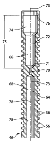
bottom of the well and then flow to the surface. Because of the low velocity,
very little
liquid if any is carried to the surface of the well by the gas.
[0006] The corresponding head of liquid in the bottom of the well exerts a
back pressure
against the producing formation, with a value corresponding to the vertical
elevation of the
CA 02718565 2010-10-25
-2-
liquid in the well, effectively terminating the well's ability to produce. A
properly applied
plunger lift system is able to bring such a well back to life and make it
profitable.
[0007] A plunger lift system permits the well to be opened and closed so as to
generate a
sufficient pressure permitting the well to flow into the flow line. The
plunger travels
freely back and forth within the vertical tubing string, from the bottom of
the well to the
surface and back to the bottom. The plunger is used as a mechanical interface
between the
gas phase and the fluid phase in the well. When the well is closed at the
surface, the
plunger rests at the bottom of the well on top of a spring assembly. Pressure
within the
well rises as gas enters the well. When the well is opened at the surface,
with all
production being through the tubing, the well begins to flow and the pressure
in the tubing
decreases. Because the trapped gas in the casing/tubing annulus remains at a
higher
pressure than the tubing, the differential pressure between the two increases.
The liquid
level in the annulus decreases as the liquid is pushed downward where it "U
tubes" into
the tubing. The mechanical tolerance between the outside diameter of the
plunger and the
inside of the tubing leaves sufficient space for the liquid to bypass the
plunger, allowing
the plunger to remain initially resting on the bottom. Eventually gas within
the tubing
causes the plunger to move up the tubing string carrying the fluid load on
top. A small
amount of gas will bypass the plunger. This is useful as it scours the plunger
and the
tubing wall of fluid keeping all the fluid on top of the plunger. If the
system has been
properly engineered, virtually all the liquid can be removed from the well to
permit the
well to flow at the lowest production pressure possible. The use of such a
plunger in the
tubing minimizes any fluid fallback over the entire length of the tubing,
irrespective of the
depth of the well. Such a well may be operated at a lower bottom hole pressure
since
substantially all the liquid is removed from the well bore, thus enhancing its
production.
[0008] In some cases, a plunger having a bypass valve that is open when the
plunger is
falling but closed when the plunger is rising in the well may be used. The
bypass valve
permits fluid to flow through the body of the plunger when open, and thus
facilitates more
rapid descent of the plunger within the well, avoiding the need to shut in the
well when the
plunger is falling. However, when closed, the bypass valve prevents fluid flow
through
the body of the plunger. With the bypass valve closed when the plunger is
rising, the
plunger can still be used to perform artificial lift.
CA 02718565 2010-10-25
-3-
[0009] A functional plunger lift apparatus requires sufficient gas to drive
the system. A
plunger lift apparatus will not work in oil wells that are producing no gas.
As used herein,
a "gas producing well" means an oil or gas well that is producing a sufficient
quantity of
gas for the implementation of a plunger lift system.
[0010] An industry misconception exists as to how much gas and pressure is
required to
successfully operate a plunger lift system. Because of this misconception,
many wells
have been placed on more expensive forms of artificial lift, such as pumping
units or the
like, than are really needed. As a result, optimum output has not been
achieved, and
capital expenditures have run much higher than necessary.
[0011] Generally accepted operating procedures suggest that a plunger lift
should be
operated at a lift speed in the range of approximately 750 feet per minute. If
the well has
too little pressure, for example so that the plunger is travelling at less
than approximately
500 feet per minute, fluid could slip around the plunger, potentially
preventing it from
rising. Conversely, if the well has too much pressure, the plunger will ascend
too quickly,
for example at a rate of greater than 1000 feet per minute, potentially
causing damage to
surface equipment due to the significant amount of kinetic energy that must be
dissipated
when the plunger arrives at the surface.
[0012] There remains a need for more efficient plungers and plungers that can
be operated
at higher velocities and/or with less risk of damage to surface equipment.
[0013] The foregoing examples of the related art and limitations related
thereto are
intended to be illustrative and not exclusive. Other limitations of the
related art will
become apparent to those of skill in the art upon a reading of the
specification and a study
of the drawings.
Summary
[0014] An aspect of the invention provides a plunger for performing artificial
lift in a gas
producing well. The plunger has a plunger body for sealingly engaging a tubing
of the
well, a fluid path through the plunger body, a passageway within the fluid
path, and a
central orifice at an end of the passageway. The plunger may have a radially
inwardly
directed lip within the fluid path and spaced above the central orifice. In
some
CA 02718565 2010-10-25
-4-
embodiments, the fluid path may have a lower chamber below the passageway and
an
upper chamber above the passageway. The upper chamber may be an internal
fishing
neck. In some embodiments, a majority of the material of the plunger by volume
may be a
material having a density of less than 4.54 g/cm3.
[0015] In some embodiments, the plunger has a bypass valve. In some
embodiments, the
bypass valve has a cage coupled to the bottom end of the plunger body and a
pin having a
head and a shaft. The pin is slideably retained within the cage and moveable
between an
open position wherein the bypass valve allows gas and liquid to flow through
the fluid
path, and a closed position wherein the pin engages a bottom of the plunger
body to limit
the flow of gas and liquid through the fluid path. A fluid passageway extends
through the
head of the pin, and has a central orifice at an end of the passageway. The
plunger with a
bypass valve may have an internal constriction within the fluid path. A
radially inwardly
directed lip within the fluid path may be provided by the internal
constriction.
[0016] In some embodiments, the plunger has a bypass valve in which the bottom
end of
the plunger has a seat for receiving a seal. The seat has one or more grooves
configured
to permit fluid to flow to the narrow passageway when the seal is sealingly
engaged with
the seat. In some such embodiments, the seal may be a ball and the seat may be
curved to
sealingly engage the ball.
[0017] In some embodiments, the plunger has a bypass valve and also has fluid
channels
through the body of the plunger for permitting fluid to flow through the
narrow
passageway when the bypass valve is in the closed position.
[0018] Another aspect of the invention provides a method of using a plunger to
perform
artificial lift in a gas-producing well. The method includes the steps of
allowing a plunger
having a fluid passageway therethrough to fall within a tubing of a well to
the bottom of
the well, allowing gas pressure to move the plunger upwardly within the
tubing, and
while the plunger is moving upwardly, allowing fluid to pass through a narrow
passageway within the fluid passageway, the narrow passageway having a central
orifice at
one end. In some embodiments, the method may include the step of allowing the
fluid
exiting the central orifice to interact with a radially inwardly directed lip
on the plunger.
CA 02718565 2010-10-25
-5-
[0019] Further aspects of the invention and features of example embodiments of
the
invention are described below.
Brief Description of Drawings
[0020] The appended drawings illustrate non-limiting example embodiments of
the
invention.
[0021] Figure 1 is a schematic representation of a gas producing well showing
a plunger
disposed therein.
[0022] Figure 2 is a side view of an embodiment of a plunger according to the
invention.
[0023] Figure 3 is a cross-sectional view of the embodiment of Figure 2.
[0024] Figure 4 is a cross-sectional view of an alternative embodiment of a
plunger having
an alternative configuration of the connecting passageway.
[0025] Figure 5 is a cross-sectional view of an embodiment of a plunger having
fluid
passageways within its lower chamber.
[0026] Figure 6 is a cross-sectional view of an alternative embodiment of a
plunger having
an internal lip.
[0027] Figure 7 is a perspective partially cut away view of a further
embodiment of a
plunger constructed as two separate pieces that are detachably joined. The
embodiment of
Figure 7 also includes a one-way valve disposed therein to permit fluid to
flow only from
the lower chamber to the upper chamber.
[0028] Figure 8A is an exploded cross-sectional view of a further embodiment
of a
plunger according to the invention having a bypass valve. Figure 8B is a cross-
sectional
view of the plunger of Figure 8A in the closed position. Figure 8C is a cross-
sectional
view of the plunger of Figure 8A in the open position.
[0029] Figure 9A is a perspective view of the cage portion of the bypass valve
of the
embodiment of Figure 8A.
CA 02718565 2010-10-25
-6-
[0030] Figure 9B is a perspective view of the pin portion of a bypass valve
that of the
embodiment of Figure 8A.
[0031] Figure 10 is a cross-sectional view of an alternative embodiment of a
pin portion of
a bypass valve that is used with the embodiment of Figure 8A.
[0032] Figure 11 is a cross-sectional view of a plunger body of a further
embodiment of a
plunger according to the invention having a bypass valve wherein the lip is
provided
separately from the internal constriction of the plunger body.
[0033] Figure 12 is a cross-sectional view of a further embodiment of a
plunger according
to the invention having a bypass valve, wherein the plunger is a two piece
Pacemaker TM-
type plunger and the valve seat has grooves to permit a limited amount of
fluid to flow
between the valve seat and the ball.
[0034] Figure 13 is a cross-sectional view of a further embodiment of a
plunger according
to the invention having a bypass valve, wherein the plunger is a two piece
Pacemaker TM-
type plunger and the plunger body includes fluid passageways that permit a
limited amount
of fluid to flow through the body of the plunger when the ball is engaged with
the valve
seat.
Description
[0035] Throughout the following description specific details are set forth in
order to
provide a more thorough understanding to persons skilled in the art. However,
well
known elements may not have been shown or described in detail to avoid
unnecessarily
obscuring the disclosure. Accordingly, the description and drawings are to be
regarded in
an illustrative, rather than a restrictive, sense.
[0036] A typical well arrangement is shown in Figure 1. A well 20 is drilled
into the
ground from the surface 22 to any producing underground formation 24. A
production
casing 26 is placed into the well bore, and perforations 28 are created in the
casing at the
level of formation 24 to allow gas and liquid to enter the well bore. A
production tubing
30 is placed inside casing 26 and forms a continuous conduit for producing gas
and liquid
up through to a wellhead lubricator 32. Lubricator 32 is arranged to place a
plunger 46 in
CA 02718565 2010-10-25
-7-
well 20 and to retrieve plunger 46 from well 20 without having to kill well
20. The
lubricator 32 may have a sensor, shown schematically as 98, to detect the
arrival of
plunger 46 at the surface 22, sending a signal to a control system 42 for
various controller
functions to help optimize production. Sensor 98 may comprise a magnetic
sensor. The
produced fluid exits through exit tubing 34 via a control valve 36 to move on
to the next
stage of collection, as indicated by arrow 38.
[0037] Well 20 includes a master valve 40, which can be used to stop the flow
from well
20. Control valve 36 is regulated based on inputs from control system 42,
which signals a
valve actuator 44 configured to regulate control valve 36.
[0038] In operation, one embodiment of plunger 46 is inserted into well 20 as
follows.
Well 20 is prevented from flowing by closing master valve 40. A plunger 46 is
inserted
into lubricator 32 by removing a cap 43, inserting plunger 46 into lubricator
32, and
replacing cap 43. Control valve 36 is kept in the closed position by valve
actuator 44,
which is controlled by input from control system 42. Master valve 40 is then
opened, and
typically control system 42 is then set to proceed with an operating mode and
allowed to
operate the well.
[0039] In the operating mode, when control valve 36 is in the closed position
so that well
20 is shut in, plunger 46 free falls by gravity for a period of time, to allow
plunger 46 to
arrive at the bottom of well 20, contacting a bottom-hole stop 48, which may
incorporate a
spring 50. Bottom-hole stop 48 absorbs impact and prevents plunger 46 from
passing
through the bottom of production tubing 30.
[0040] After a period of time in the operating mode, control system 42 will
signal valve
actuator 44 to open control valve 36. This time period may be an established
set time; a
time calculated from other parameters such as plunger arrival time; a time
calculated from
pressure readings from casing 28, tubing 34, or a downstream collection
system; or some
combination of the foregoing; or, the time frame may be established in any
other suitable
manner. Control system 42 may also be manually operated to open control valve
36.
[0041] Upon control valve 36 opening, gas pressure which has accumulated in
the annulus
52 between casing 26 and tubing 30 will flow through bottom-hole stop 48.
Plunger 46
acts like a piston, providing a seal between the gas and liquid entering from
below plunger
CA 02718565 2010-10-25
-8-
46 and the gas and liquid above plunger 46. Plunger 46 pushes liquid that has
accumulated above plunger 46 to the surface 22, where it exits the pumping
system, as
shown by arrow 38, and is transported to a downstream separation and gathering
apparatus.
[0042] Plunger 46 may remain in well 20 for a period of operation which may be
from
days or weeks up to several years depending on performance, well conditions,
and the
nature of plunger 46 or other well components used.
[0043] With reference to Figure 2, in one embodiment plunger 46 has an
elongated body
54. Plunger 46 is preferably made from metallic materials such as steel,
titanium or the
like, and portions of plunger 46 may be made from two or more different types
of such
materials. In some embodiments, at least a portion of plunger 46 is made from
a magnetic
material, which may facilitate retrieval of plunger 46 or detection of plunger
46 arriving at
the surface 22.
[0044] Heavy plungers operated at higher speeds have a significant amount of
kinetic
energy, and can cause damage to equipment used in well 20. For example, the
force of
plunger 46 arriving at the surface 22 may damage lubricator 32 if the plunger
has more
kinetic energy than lubricator 32 can safely dissipate when catching plunger
46.
[0045] In some embodiments wherein plunger 46 is approximately 25 cm long and
has a
diameter of approximately 5 cm, plunger 46 may have a weight of less than four
pounds
(i.e. approximately 1.8 kg), for example approximately two pounds (i.e.
approximately
0.9 kg). In some embodiments, a majority of the material from which plunger 46
is
constructed (measured by volume) may be a material having a density of 4.54
g/cm3 or
less. A plunger having a lower weight will have less kinetic energy during
operation at the
same speed as a heavier plunger, which aids in decreasing the impact of the
plunger when
it arrives at the surface 22 or bottom of well 20. Thus, a lighter plunger may
be safely
operated at higher velocities than an equivalent heavy plunger. Operation of a
plunger lift
at higher frequency to lift smaller volumes of liquid can be more efficient
than lifting
larger amounts of liquid less frequently.
[0046] In some embodiments, a plunger having a weight of five pounds (i.e.
approximately 2.3 kg) or less is operated to travel in tubing 30 at maximum
speeds of at
CA 02718565 2010-10-25
-9-
least 800 feet per minute (i.e. approximately 4 metres per second). In some
such
embodiments, the lifting and falling of plunger 46 may be repeated at a
frequency of up to
6 times per hour depending on the depth of well 20.
[0047] In some embodiments, the bottom 55 of plunger body 54 may be slightly
tapered or
cone-shaped, which may facilitate descent of plunger 46.
[0048] The outer surface 60 of plunger body 54 may be configured in a manner
effective
to provide the desired level of sealing with tubing 30 depending on the
conditions
prevailing in well 20. As used herein, "sealingly engages" means that the
plunger seals
against tubing 30 sufficiently well to perform artificial lift of liquids. A
complete seal is
not required to perform artificial lift, and the passage of small amounts of
gas and/or liquid
between the plunger and the tubing is not detrimental and can be beneficial.
[0049] In the illustrated embodiment, plunger body 54 has a series of axially
spaced ribs
56 defining grooves 58 therebetween on its outer surface 60. The combination
of ribs and
grooves may create turbulence in any fluid that passes between plunger 46 and
the inner
surface of production tubing 30. Such turbulence may improve the ability of
plunger 46 to
maintain a seal and act effectively as a piston. Alternatively, plunger 46 may
have other
surface characteristics known for use on plungers to accommodate a variety of
different
operating conditions, such as solid rings, shifting rings, spring loaded
interlocking pads, a
spiral-wound brush surface, or the like.
[0050] Outer surface 60 may also incorporate one or more monitoring grooves
62, or
other markings or indicia on the surface, to indicate wear. Such markings may
be
observed by an operator, who may periodically remove plunger 46 for inspection
to
determine if plunger 46 is worn to a point where replacement may be
recommended.
Outer surface 60 may also be provided with catching grooves 61, to facilitate
capture of
plunger 46 at the surface 22 of well 20 by a mechanism such as a ball detent
(not shown)
within lubricator 32.
[0051] With reference to Figure 3, plunger body 54 defines a fluid path
through a bore 64
of plunger 46. In the illustrated embodiment, bore 64 has an upper chamber 66,
a lower
chamber 68, and a connecting passageway 70. As used in this specification,
"upper"
means the portion of plunger 46 that is oriented towards the surface 22 of
well 20 when
CA 02718565 2010-10-25
-10-
plunger 46 is in use, and "lower" means the portion of plunger 46 that is
oriented towards
the bottom of well 20 when plunger 46 is in use. "Inwardly" means a direction
towards
the central axis of well 20, and "outwardly" means a direction towards casing
26 of well
20. It will be appreciated that plunger 46 could have other orientations when
not in use.
[0052] Connecting passageway 70 is narrower than chambers 66 and 68 and has an
upper
orifice 71 at its upper end. Upper orifice 71 may be provided for example by a
plug with
a hole therethrough. The plug may be removable, for example by being
threadably
engaged within connecting passageway 70. In the embodiment of Figure 7, upper
orifice
71 is provided by a hex plug 80 that is threadably engaged with a
correspondingly threaded
surface on connecting passageway 70. The plug may be made of steel or another
suitable
material.
[0053] In the embodiment illustrated in Figure 3, connecting passageway 70 is
cylindrical,
and both passageway 70 and upper orifice 71 are concentric with chambers 66
and 68 and
with the central longitudinal axis 73 of plunger 46 (i.e. upper orifice 71 is
centrally
located). In this embodiment, all of connecting passageway 70, upper orifice
71, and
chambers 66 and 68 have a circular cross-section. Passageway 70 and upper
orifice 71 are
narrower than chambers 66 and 68. Chambers 66 and 68 may have different
widths, or
may have the same width.
[0054] The diameter of connecting passageway 70 and orifice 71 may be selected
to be
wider or narrower based on the particular operating characteristics of well 20
(as described
below). Suitable ratios of the diameter of orifice 71 to the diameter of
plunger 46 may
range from about 1:25 to 1:2.5 (i.e. the diameter of orifice 71 may be in the
range of 4%
to 40% of the diameter of plunger 46). For example, in embodiments where
plunger 46
has a diameter of approximately 4.9 cm, orifice 71 may be in the range of
about 2 mm to
about 20 mm in diameter. In some such embodiments, orifice 71 may have a
diameter of
approximately 4.7 mm in a well operating at typical pressure, or approximately
6.0 mm,
approximately 8.0 mm, or approximately 10.0 mm in diameter if the well is
operating at
higher pressure (i.e. to provide a ratio of the diameter of orifice 71 to the
diameter of
plunger 46 of approximately 1:10, 1:8, 1:6 or 1:5, respectively).
[0055] In some embodiments, alternative configurations for connecting
passageway 70
may be used. For example, in the embodiment illustrated as plunger 46B in
Figure 4, the
CA 02718565 2010-10-25
-11-
fluid pathway between lower chamber 68 and upper chamber 66 is provided by a
pair of
connecting channels 77 that are narrower than chambers 66 and 68 and join
together at
their upper ends to permit fluid to flow through upper orifice 71. Upper
orifice 71 is
centrally located.
[0056] Upper chamber 66 is provided with a radially inwardly directed lip 76
spaced
upwardly apart from the upper edge of connecting passageway 70 by a distance
75. Lip 76
is shown in the illustrated embodiment as being on the upper edge of upper
chamber 66,
although lip 76 could be placed within upper chamber 66. Distance 75 is
sufficient to
allow fluid discharged through connecting passageway 70 to interact with lip
76. Distance
75 may, for example, be in the range of approximately 10% to approximately 60%
of the
total length of plunger 46. For example, in an embodiment wherein plunger 46
is
approximately 25 cm long, distance 75 may be approximately 13 cm.
[0057] Lip 76 extends radially inwardly for a sufficient distance and has a
suitable
configuration (e.g. generally perpendicular to the inner surface of bore 64)
to enable lip 76
to interact with the fluid flow being discharged through connecting passageway
70 when
plunger 46 is being forced upwardly within well 20 (as described below).
However, lip 76
does not extend so far inwardly as to significantly impede the flow of fluid
through bore
64 of plunger 46 during operation.
[0058] In the illustrated embodiment of Figures 3 and 4, upper chamber 66 is
divided into
two portions, 72 and 74. Portion 74 of upper chamber 66 provides an internal-
type fishing
neck for use with a conventional plunger pulling tool (not shown). A plunger
pulling tool
can be used to return plunger 46 to the surface 22 by wireline recovery should
plunger 46
fail to rise to the surface. Lip 76 may project inwardly by approximately 0.3
cm in such
an embodiment.
[0059] Lower chamber 68 may optionally incorporate one or more additional
fluid
passageways 78 that connect lower chamber 68 to the outer surface 60 of
plunger 46 and
allow fluid to flow between lower chamber 68 and the interior of tubing 30. As
shown in
Figure 5, in some embodiments, fluid passageways 78 may intersect lower
chamber 78
radially (78A) or tangentially (78B). Fluid passageways 78 may allow plunger
46 to
descend more quickly within well 20, and may permit some gas to pass between
plunger
46 and tubing 30, to decrease friction therebetween.
CA 02718565 2010-10-25
-12-
[0060] During the portion of the well operating cycle when control valve 36 is
in the
closed position and the flow of gas and liquid through the system has stopped,
the pressure
will fall within tubing 30. Chambers 66 and 68 together with connecting
passageway 70
provide a fluid path through plunger 46, allowing gas and liquid to pass
through the
interior of elongated plunger body 54. Such fluid flow allows for a faster
rate of descent
of plunger 46 than would be the case if the plunger were formed as a solid
body or without
a fluid path therethrough. Thus, a lighter plunger, which will have a lower
risk of causing
damage to the components of well 20, may be operated at the same frequency as
a heavier
plunger that does not have a fluid path therethrough. Fluid passageways 78
further assist
in achieving relatively fast descent. The faster rate of descent can be
achieved without the
use of special valves or any moving components to alter or regulate the rate
of descent.
[0061] When the well cycle is changed by control system 42 to open control
valve 36,
plunger 46 will be affected by the flow of gas from the high pressure
accumulated in
annulus 52 to the low pressure at the exit point of the well system, where the
fluid moves
on to the next stage of collection, designated by arrow 38. Fluid will enter
lower chamber
68 and encounter resistance as it enters connecting passageway 70, thereby
exerting some
upward force on plunger 46.
[0062] Without being limited by any theory of operation, the narrow connecting
passageway 70 is thought to create a venturi effect whereby gas flow effects a
change in
velocity of the fluid (which is increased), and the pressure of the fluid flow
is decreased
within connecting passageway 70. The fluid flow through connecting passageway
70 will
occur at an accelerated velocity and lower pressure as compared to the
velocity of the fluid
flow in lower chamber 68. The resultant low pressure jet of fluid exits
through upper
orifice 71, thereby providing a lower pressure above plunger 46. This effect
and the
resulting positive differential pressure between lower chamber 68 and the
region above
plunger 46 create an upward force affecting the entire plunger 46. The
resultant lift effect
on plunger 46 improves its ability to move liquid and gas load carried above
it to the
surface 22.
[0063] The fluid flowing into upper chamber 66 through connecting passageway
70 and
upper orifice 71 interacts with lip 76, exiting upper orifice 71 at increased
velocity,
expanding radially outwardly in a V-shape, and impacting against lip 76. This
effect
CA 02718565 2010-10-25
- 13 -
provides additional upward force on plunger 46. Fluid exiting connecting
passageway 70
fans outwardly generally with a V-shape from orifice 71 on the central axis of
plunger 46
toward lip 76, and accordingly distance 75 should be sufficiently large and
lip 76 should
project inwardly to an extent sufficient to allow the exiting fluid to
interact with lip 76.
[0064] The fluid path through plunger 46 and resultant turbulent flow of fluid
from lower
chamber 68 through connecting passageway 70 and into upper chamber 66 also
cleans
upper chamber 66 of debris, such as sand, salt, paraffin or scale, all of
which are common
elements found in a well operation. This maintains the functionality of the
venturi effect
and keeps internal fishing neck 74 clear and accessible for retrieval of
plunger 46 by a
wireline (not shown), should this become necessary.
[0065] Figure 6 illustrates an alternative embodiment of a plunger 46C in
which an
internal lip 76A is provided within upper chamber 66 spaced apart from upper
orifice 71
by distance 75. A conventional internal-type fishing neck is provided at the
upper end of
plunger 46C, and internal lip 76A is spaced sufficiently below the internal-
type fishing
neck that it will not interfere with the use of a conventional plunger pulling
tool to retrieve
plunger 46C.
[0066] In another embodiment, illustrated in Figure 7, a removably fastened
size-
modifying insert, illustrated as screw plug 80, is provided within connecting
passageway
70 to fluidly connect chambers 66 and 68. In the illustrated embodiment, at
least a portion
of screw plug 80 has a threaded outer surface 84, which is engageable with a
correspondingly threaded surface 86 of connecting passageway 70. The size-
modifying
insert could alternatively be removably fastened in any suitable manner, such
as by a
friction fit engagement. The size-modifying insert has a narrow bore 82
extending
therethrough to permit the opening in connecting passageway 70 to be changed
to be
narrower by providing a bore of a somewhat smaller diameter therein.
[0067] It may be necessary or desirable to provide a narrower bore, for
example based on
the conditions under which plunger 46 is operating, the velocity at which it
is desired to
operate plunger 46, or the weight of plunger 46. For example, in a well with a
lower
pressure of flow, for a heavier plunger, or where a faster operating velocity
is desired, a
narrower bore would be used, for example wherein the ratio of the diameter of
orifice 71
to the diameter of plunger 46 is approximately 1:10 or 1:25. A wider bore
wherein the
CA 02718565 2010-10-25
-14-
ratio of the diameter of orifice 71 to the diameter of plunger 46 is
approximately 1:8, 1:6,
1:5, or 1:2.5 may also be provided, for example.
[0068] A plurality of different screw plugs having a range of differently
sized bores 82
may be provided for use with plunger 46, so that an appropriate screw plug can
be inserted
in plunger 46 to adjust the width of connecting passageway 70. Plunger 46 may
optionally
be provided in a kit with two or more size-modifying inserts, such as screw
plugs 82,
having different bore diameters.
[0069] In a further embodiment, illustrated in Figure 7, a suitable one-way
valve 86 such
as a duck bill valve or the like may be arranged on or within connecting
passageway 70, to
ensure that fluid flows only from lower chamber 68 to the upper chamber 66 of
plunger
46. For example, one-way valve 86 could be coupled to screw plug 80 as
illustrated (e.g.
at the upper end of screw plug 80), or to the internal surface of plunger body
54.
[0070] In a further embodiment, plunger 46 may be constructed as two separate
pieces that
are joined in a suitable manner. In the embodiment shown in Figure 7, an upper
portion
90 of plunger 46 is detachably coupled to a lower portion 92 of plunger 46 by
means of a
screw-threaded engagement of corresponding threaded surfaces 94 (on lower
portion 92)
and 96 (on upper portion 90). Such a configuration facilitates access for
changing screw
plug 80 and/or one-way valve 88 by permitting the two portions of plunger 46
to be
separated.
[0071] In some embodiments, upper and lower portions 90 and 92 of plunger 46
may be
manufactured from different materials. For example, a relatively light
material such as
titanium may be used to manufacture lower portion 92 to reduce the mass of
plunger 46,
while steel may be used to manufacture upper portion 90, to permit detection
of plunger 46
by a magnetic sensor (for example shown schematically as sensor 98 in Figure
1), which
may be used to detect the arrival of plunger 46 at the surface 22.
[0072] In some embodiments, one or more instruments used for measuring certain
operating parameters of well 20, for example an instrument for measuring
temperature or
pressure, may be carried by plunger 46. In exemplary embodiments, such
instruments
may be secured within lower chamber 68 of plunger 46 to record operating
parameters
within well 20, for example at the bottom of well 20. The instruments may be
secured
CA 02718565 2010-10-25
- 15-
within lower chamber 68 in any suitable manner, for example on threaded
surface 86 of
connecting passageway 70. The instrument may comprise a memory capable of
recording
the operating parameters so measured. The memory may also be secured within
lower
chamber 68, and may optionally log the measured parameters for a period of
time. An
operator may retrieve information about the measured operating parameters by
accessing
lower chamber 68 when plunger 64 has been returned to the surface 22 of well
20 and
removed through lubricator 32, for example during routine inspection of
plunger 46 or at
other desired intervals.
[0073] In a further exemplary embodiment having a bypass valve, illustrated as
plunger
300 in Figures 8A to 9B, a bypass valve 302 is provided to permit plunger 300
to descend
in well 20 when well 20 is flowing. Bypass valve 302 is in the open position
when
plunger 300 is falling downwardly within well 20 to permit fluid to flow
therethrough and
facilitate rapid descent of plunger 300, and in the closed position when
plunger 346 is
ascending within well 20 to limit fluid flow through plunger 300 and permit
plunger 346
to be lifted upwardly by gas pressure within well 20.
[0074] In the illustrated embodiment, bypass valve 302 has a cage 304 with a
pin 306
inserted therein. Bypass valve 302 is secured to the bottom 308 of plunger
300. In the
illustrated embodiment, a bottom portion of outer surface 310 of plunger body
312 is a
threaded portion 314, and engages with a correspondingly threaded surface 316
on an
inner surface of the upper portion of cage 304. A fluid path 317 is provided
through cage
304 from the bottom 308 of plunger 300 to the top 318 of plunger 300.
[0075] Cage 304 has an axially extending bore 320 defined therethrough. Bore
320 has a
relatively wider upper portion 322 and a relatively narrower lower portion
324. Cage 304
may have at least one axially extending slot 326 on the outside surface of the
lower
portion thereof, extending from base 320 of cage 304 upwardly to a point above
narrower
portion 316. At least one aperture 328 is provided in cage 304 through wider
upper
portion 322 of bore 320 to provide a fluid path therethrough. Aperture 328 may
be
formed by the intersection of slot 326 and wider upper portion 322. In the
illustrated
embodiment, three symmetrically disposed slots 326 and apertures 328 are
provided. Slot
326 does not extend fully through the material of cage 304 where slot 326
intersects
narrower portion 324 of bore 320 in the illustrated embodiment, although it
optionally
could do so.
CA 02718565 2010-10-25
-16-
[0076] To enhance the coupling between cage 304 and plunger body 312, an
aperture 330
may be provided through threaded portion 316 of cage 304 to optionally receive
a
setscrew or weld plug (not shown).
[0077] A pin 306 is slidably disposed within bore 320 of cage 304. Pin 306 has
an
elongate shaft portion 332 and a wider head portion 334. Head portion 334 is
disposed
within wider upper portion 322 of bore 320 and is slidable in an axial
direction therein.
The diameter of head portion 334 is sufficiently large so that pin 306 cannot
slide through
lower portion 324 of bore 320, and also so that pin 306 can seal against
plunger body 312
as described below. Upper portion 336 of pin 306 makes contact with an inner
lip 338 on
the inner surface of the bottom 308 of plunger body 312 when bypass valve 302
is in the
closed position, to limit passage of gas and fluid between pin 306 and plunger
body 312.
Upper portion 336 may have an angled portion 340 that contacts a
correspondingly shaped
angled portion of inner lip 338.
[0078] Shaft portion 332 of pin 306 sits within bore 320 and projects
downwardly from
head portion 326. The bottom end 339 of pin 306 extends outside of the bottom
341 of
cage 304 when bypass valve 302 is in the open position, and is sufficiently
long to move
head portion 334 into the fully closed position when pin 306 contacts bottom-
hole stop 48
as described below.
[0079] Head portion 334 is configured to permit a desired amount of gas or
liquid to pass
through pin 306 when bypass valve 302 is in the closed position by including a
fluid path
therethrough. The fluid path may extend through or into shaft portion 332, so
long as it is
positioned to permit fluid flow therethrough when pin 306 is in the closed
position. In the
illustrated embodiment, head portion 334 has three symmetrically disposed
cylindrical
fluid paths 342 extending between lower edge 344 and upper edge 336 of head
portion
334. Other configurations for the fluid path may be used. Fluid paths 342 join
at a
central orifice 346 of pin 306 which is concentric with a central axis 348 of
plunger 300.
Fluid paths 342 allow a desired amount of fluid to pass through bypass valve
302 even
when bypass valve 302 is in the closed position, thus providing a venturi
effect through
central orifice 346 as described above with reference to orifice 71. Fluid
flow through
orifice 346 also keeps bypass valve 302 free of debris such as sand, salt,
paraffin or scale,
CA 02718565 2010-10-25
- 17-
enabling pin 306 to slide within cage 304 (as described below) without
obstruction by such
debris.
[0080] As an example of an alternative fluid path configuration within pin
306, the fluid
path could be provided by a single central bore through the entirety of the
length of pin
306 leading to central orifice 346, illustrated as bore 350 in pin 306A in
Figure 10.
[0081] In the case of plunger 300, when bypass valve 302 is in the closed
position, gas
and liquid under pressure in annulus 52 will enter lower chamber 350 of
plunger 300,
encountering resistance as it enters fluid paths 342, thereby exerting an
upward force on
plunger 300. Narrow fluid paths 342 also create a venturi effect as described
with
reference to connecting passageway 70 above. Connecting passageway 70 is not
present
in plunger 300. The fluid flow through fluid paths 342 will occur at an
accelerated
velocity as compared with the rate of fluid flow through bore 320 of cage 304
and the rate
of fluid flow through plunger body 312. The pressure of fluid exiting through
orifice 346
is thus reduced, which decreases the pressure above plunger 300.
[0082] Fluid exits orifice 346 and fans outwardly generally with a V-shape
from the
central axis 348 of plunger 300 and encounters lip 352 of lower chamber 350 of
plunger
300. Lip 352 is spaced apart from orifice 346 by a distance 354, which is
sufficiently
large to allow the fluid exiting orifice 346 to interact with lip 352, and has
a configuration
suitable for allowing fluid to apply upward force against lip 352 (e.g. lip
352 may be
generally perpendicular to the inner surface of plunger body 312). For
example, distance
354 may be in the range of 10% to 50% of the length of plunger body 312.
[0083] In the illustrated embodiment of Figure 8A, lip 352 is provided by the
lower edge
of the internal constriction formed where fluid path 317 narrows into bore
356, described
below. However, as illustrated in Figure 11, a lip may alternatively be
provided as a
separate member 353 on plunger 300A.
[0084] Plunger 300 functions in a manner generally similar to plunger 46.
Bypass valve
302 allows plunger 300 to fall even while well 20 is flowing, meaning well 20
does not
need to be shut in while plunger 300 is falling. In operation, bypass valve
302 is placed
into the closed position (shown in Figure 8B) when bottom end 339 of pin 306
contacts
bottom-hole stop 48 when plunger 300 has descended to the bottom of well 20.
CA 02718565 2010-10-25
- 18-
Movement of pin 306 upwardly relative to cage 304 places head portion 334 in
contact
with inner lip 338 of plunger body 312. The force of the gas pressure within
tubing 30
against the lower side of head portion 334 holds pin 306 in the closed
position. Fluid
paths 342 are narrow enough that sufficient force is maintained against the
lower side of
head portion 344 by the pressure of gas and fluid within tubing 30 to hold pin
306 in the
closed position. Plunger 300 then rises to the surface 22 as described above
by reason of
the upward force applied to plunger 300 by the fluid pressure in tubing 30.
[0085] When plunger 300 reaches the surface 22, it should rise sufficiently
far into
lubricator 32 that the entirety of plunger 300, including bypass valve 302, is
above exit
tubing 34. The gas pressure against the lower side of head portion 334 is thus
released as
gas and liquid are permitted to exit well 20 via exit tubing 34, and pin 306
drops within
cage 304 into the open position (shown in Figure 8C) by gravitational force.
This
facilitates the descent of plunger 300, even while well 20 is flowing. The use
of gas
pressure to keep pin 306 in the closed position and gravitational
force/release of gas
pressure to move pin 306 into the open position means no additional parts or
mechanisms
are required to operate bypass valve 302.
[0086] To better control the rate of descent of plunger 300, an internal
constriction is
provided within fluid path 317. The internal constriction slows the rate of
descent of
plunger 300 when bypass valve 302 is open. In the illustrated embodiment, bore
356
provides the internal constriction within plunger 300. Bore 356 may be
threaded to
receive inserts having passageways of varying widths therethrough to allow
selection of an
appropriate diameter for bore 356 depending on the conditions prevailing in
well 20. In
some embodiments, the insert may be a screw plug. A plurality of screw plugs
having
diameters of varying widths may be provided in a kit with plunger 300.
[0087] In the illustrated embodiment of Figures 8A to 8C, plunger body 312 has
an upper
chamber 358 that is divided into two portions, the upper portion being an
internal-type
fishing neck 360. Fishing neck 360 allows for retrieval of plunger 300 by
conventional
wireline methods, as described above for plunger 46. Other upper chamber
configurations
may be used for plunger 300.
[0088] Plunger 300, including bypass valve 302 is made from a metallic
material. In
some embodiments, all or a portion of bypass valve 302 is made from a magnetic
material
CA 02718565 2010-10-25
- 19-
such as steel to facilitate detection of bypass valve 302 by a magnetic
arrival sensor upon
arrival within lubricator 32. Other portions of plunger 300 may be made from
other
metallic materials. In some embodiments, plunger body 312 is made from non-
magnetic
material such as titanium while at least a portion of bypass valve 302 is made
from a
magnetic material such as steel so that magnetic arrival sensor 98 is not
triggered until
bypass valve 302 arrives at magnetic arrival sensor 98. Because pin 306 falls
into the
open position by gravitational force when the upward force applied by fluid
pressure
within tubing 30 is released, bypass valve 302 must fully pass exit tubing 34
when plunger
300 arrives at surface 22 to ensure reliable functioning of plunger 300.
Forming at least a
portion of bypass valve 302 from a magnetic material while other portions of
plunger 300
are formed from non-magnetic material facilitates reliable detection of the
fact that plunger
346 has been received properly within lubricator 32. If plunger 300 is not
properly
received, as indicated for example by a failure to trigger magnetic arrival
sensor 98, an
operator may take appropriate corrective action, for example by briefly
shutting in well
20.
[0089] In other embodiments, a different type of bypass valve may be used with
the
plunger. For example, a valve of the type found in PacemakerTM two-piece
plungers may
be used. Such plungers have a seat on their lower ends. A separate ball is
dropped into
the well tubing ahead of the plunger. The ball can seal against the seat. In
an exemplary
embodiment illustrated as plunger 400 in Figure 12, plunger 400, which is
generally
similar in design and function to plunger 300, includes a fluid passageway
470, an orifice
472 at an upper end of fluid passageway 470, a lower chamber 450 in fluid
communication with orifice 472, an upper chamber 458, and a lip 452 between
lower
chamber 450 and upper chamber 458. At its lower end, plunger 400 has a curved
seat 474
for receiving a ball seal 480. Seat 474 includes grooves 476. When ball 480 is
engaged
with seat 474, grooves 476 define a fluid passageway between ball 480 and
plunger 400.
When plunger 400 is falling, ball 480 falls separately from plunger 400,
allowing fluid to
flow rapidly through plunger 400. When plunger 400 reaches bottom hole stop
48, ball
480 is engaged with seat 474, and the force of gas pressure within tubing 30
holds ball
480 against seat 474. Grooves 476 permit fluid to flow between seat 474 and
ball 480 into
fluid passageway 470 and through orifice 472, thus providing a venturi effect
as described
above with reference to orifice 71 and central orifice 346. Fluid enters lower
chamber
450, engages with lip 452 as described above with reference to lip 352, and
passes into
upper chamber 458 where it can exit plunger 400 (i.e. fluid can travel through
a fluid path
CA 02718565 2010-10-25
-20-
in the body of plunger 400). Fluid passageway 470 and orifice 472 may be
concentric
with a central axis 448 of plunger 400.
[0090] Using similar principles, valves having valve members of alternative
shapes may
be used. The valve member and/or a valve seat against which the valve member
can
engage may be grooved or textured so that when the valve is "closed" with the
valve
member against the seat, a desired amount of fluid is allowed to pass into the
plunger
body to provide a venturi effect as described above. Alternatively, as
described for
example with reference to plunger 300, a fluid passageway may be provided
through a
valve member of alternative shape to allow a desired amount of fluid to pass
into the
plunger body to provide a venturi effect as described above.
[0091] In other embodiments having a bypass valve, fluid channels allowing
fluid to flow
through the body of the plunger itself when the bypass valve is in the closed
configuration
may be used. The fluid channels can allow fluid to flow through an orifice of
the plunger
body to provide a venturi effect when the bypass valve is in the closed
configuration. For
example, in the embodiment illustrated as plunger 500 in Figure 13, a pair of
fluid
channels 590 are formed in the bottom of plunger 500. Fluid channels 590 are
configured
to allow fluid to flow through the body of plunger 500 even when the bypass
valve,
illustrated as a PacemakerTM-type two-piece plunger system in Figure 13, is in
the closed
position. Plunger 500 is generally similar in design and function to plunger
400, and
includes a fluid passageway 570, an orifice 572 at an upper end of fluid
passageway 570,
a lower chamber 550 in fluid communication with orifice 572, an upper chamber
558,
with a lip 552 between lower chamber 550 and upper chamber 558. At its lower
end,
plunger 500 has a curved seat 592 for receiving a ball 480. Plunger 500
operates in a
generally similar manner to plunger 400, except that fluid flows into fluid
passageway 570
and orifice 572 through fluid channels 590 when ball 580 is engaged with seat
592 when
plunger 500 is travelling upwardly within well 20. Orifice 572 and fluid
passageway 570
may be concentric with the central axis 548 of plunger 500. The configuration
of fluid
channels 590 is not critical, so long as fluid channels 590 permit a desired
amount of fluid
to flow through orifice 572 when ball 580 is engaged with seat 592, thereby
providing a
fluid path through plunger 500 to orifice 572.
CA 02718565 2010-10-25
-21-
[0092] While a number of exemplary aspects and embodiments have been discussed
above, those of skill in the art will recognize certain modifications,
permutations,
additions and sub-combinations thereof. For example:
= a removable size-modifying insert such as screw plug 80 could be engaged
within connecting passageway 70 in any suitable manner, for example by means
of a friction fit, latch mechanism or the like;
= upper portion 90 of plunger 46 could be coupled to lower portion 92 in any
suitable manner, for example by means of a friction fit, latch mechanism or
the
like;
= the plunger body in any embodiment could be constructed as two separate
pieces
that are joined in a suitable manner, as described with reference to plunger
46;
= all or portions of the plunger could be constructed from a plurality of
separable
pieces joined in a suitable manner;
= fluid passageways that connect the lower chamber to the outer surface of the
plunger body could optionally be provided in any embodiments of plunger; or
= instruments for measuring certain operating parameters may be secured within
the lower chamber of embodiments of the plunger as described for plunger 46,
and a bore within the body of the plunger may be internally threaded to
receive
such instruments.
Mutually non-exclusive features of the embodiments described above can all be
incorporated or combined together in other embodiments that are within the
scope of the
present invention. It is therefore intended that the following appended claims
and claims
hereafter introduced are interpreted to include all such modifications,
permutations,
additions and sub-combinations as are within their true spirit and scope.