Note: Descriptions are shown in the official language in which they were submitted.
CA 02718717 2010-09-16
WO 2009/116872 PCT/N02009/000099
1
METHOD AND APPARATUS FOR MONITORING THE AUTONOMOUS
NERVOUS SYSTEM OF A SEDATED PATIENT
TECHNICAL FIELD
The invention relates in general to medical technology, and in particular to a
method and an apparatus for monitoring a sedated patient.
BACKGROUND OF THE INVENTION
During surgery it is very important to observe the patient's level of
consciousness
and awareness. Few reliable methods of observation exist today. In the field
of
medical technology there is a problem in producing physical measurements
representing the activity in an individual's autonomous nervous system, i.e.
in the
part of the nervous system, which is beyond the control of the will.
Particularly, there is a special need to monitor the autonomous nervous system
of a
sedated, non-verbal patient, e.g. a patient in anaesthesia or an artificially
ventilated
patient, in order to detect if the patient needs more hypnotics because of
awakening
stimuli or more analgesia because of pain stimuli.
Tests have shown that the skin's conductance changes as a time variable signal
which, in addition to a basal, slowly varying value (the so-called basal level
or the
average conductance level through a certain interval), also has a component
consisting of spontaneous waves or fluctuations.
The basal level and the characteristics of the fluctuations may be viewed on a
display by a skilled, human operator (e.g., the surgeon or the
anesthesiologist), in
order to monitor the autonomous nervous system of the patient.
RELATED BACKGROUND ART
WO-03/94726 discloses a method and an apparatus for monitoring the autonomous
nervous system of a sedated patient. In the method, a skin conductance signal
is
measured at an area of the patient's skin. Certain characteristics, including
the
average value of the skin conductance signal through a time interval and the
number
of fluctuation peaks through the interval, is calculated. Based on these
characteristics, two output signals are established, indicating
pain/discomfort and
awakening in the patient, respectively. The awakening signal is established
based on
the number of fluctuations and the average value through an interval.
CA 02718717 2010-09-16
WO 2009/116872 PCT/N02009/000099
2
SUMMARY OF THE INVENTION
An object of the present invention is to provide an improved method and an
improved apparatus for monitoring a sedated patient.
The method and the apparatus are defined by the appended claims.
BRIEF DESCRIPTION OF THE DRAWINGS
The principle of the invention will be disclosed in the following by an
example
embodiment, illustrated in the figures.
Figure 1 illustrates a block diagram for a preferred embodiment of an
apparatus
according to the invention.
Figure 2 illustrates a flow chart for a method according to the invention.
DETAILED DESCRIPTION OF THE INVENTION
Figure 1 illustrates a block diagram for a preferred embodiment of an
apparatus
according to the invention.
Substantial parts of the apparatus' hardware structure is previously described
in the
Applicant's related patent application published as WO-03/94726, with
particular
reference to the block diagram in the publication's fig. 1 and the
corresponding,
detailed description. The disclosure of this publication, and the apparatus
hardware
structure in particular, is hereby expressly incorporated by reference.
On an area 2 of the skin on a body part 1 of the patient, sensor means 3 are
placed
for measuring the skin's conductance. The body part 1 is preferably a hand or
a foot,
and the area 2 of the skin on the body part 1 is preferably the palmar side of
the
hand or the plantar side of the foot. Alternatively, the body part 1 may be
the
forehead of the patient. The sensor means 3 comprise contact electrodes where
at
least two electrodes are placed on the skin area 2. In a preferred embodiment
the
sensor means 3 consist of three electrodes: a signal electrode, a measuring
electrode
and a reference voltage electrode, which ensures a constant application of
voltage
over the stratum corneum (the surface layer of the skin) under the measuring
electrode. The measuring electrode and the signal electrode are preferably
placed on
the skin area 2. The reference voltage electrode may also be placed on the
skin area
CA 02718717 2010-09-16
WO 2009/116872 PCT/N02009/000099
3
2, but it is preferably placed in a nearby location, suitable for the
measuring
arrangement concerned.
In an embodiment, an alternating current is used for measuring the skin's
conductance. The alternating current advantageously has a frequency in the
range of
up to 1000 Hz, such as 88 Hz. A signal generator, operating at the specified
frequency, applies a signal current to the signal electrode.
The resulting current through the measuring electrode is conveyed to a
measurement
converter 4, which includes a current to voltage converter and a decomposition
circuit which provides the conductance real part of the complex admittance.
The measurement converter 4 may also comprise amplifier and filter circuits.
In the
preferred embodiment the measurement converter contains low-pass filters, both
at
the input and at the output. The object of the input low-pass filter is to
attenuate
high-frequency noise, for instance coming from other medical equipments, and
also
to serve as anti-aliasing filter to prevent high frequency components from
being
received by subsequent circuits for time discretization.
The control unit 5 comprises a time discretization unit 51 for time
discretization of
the signal from the measurement converter. The time discretization takes place
at a
sampling rate, which may advantageously be in the order of 20 to 200 samplings
per
second. The control unit further comprises an analog-digital converter 52,
which
converts measurement data to digital form.
The control unit 5 also comprises a processing unit 53 for processing the
digitized
measurement data, storage means in the form of at least one store for storing
data
and programs, illustrated as a non-volatile memory 54 and a random access
memory
55. The control unit 5 further comprises an output interface circuit 61, which
provides output signals 71, 72. Preferably, the control unit 5 further
comprises a
display interface circuit 81, which is further connected to display unit 8.
The control
unit 5 may also advantageously comprise a communication port 56 for digital
communication with an external unit, such as a personal computer 10.
In a preferred embodiment the non-volatile memory 54 comprises a read-only
storage in the form of programmable ROM circuits, or alternatively Flash
memory
circuits, containing at least a program code and permanent data, and the
random
CA 02718717 2010-09-16
WO 2009/116872 PCT/N02009/000099
4
access memory 55 comprises RAM circuits, for storage of measurement data and
other provisional data.
The control unit 5 also comprises an oscillator (not shown), which delivers a
clock
signal for controlling the processing unit 53. The processing unit 53 also
contains
timing means (not shown) in order to provide an expression of the current
time, for
use in the analysis of the measurements. Such timing means are well-known to
those skilled in the art, and are often included in micro controllers or
processor
systems which the skilled person will find suitable for use with the present
invention.
The control unit 5 may be realized as a microprocessor-based unit with
connected
input, output, memory and other peripheral circuits, or it may be realized as
a micro
controller unit where some or all of the connected circuits are integrated.
The time
discretization unit 51 and/or analog-digital converter 52 may also be included
in
such a unit. The choice of a suitable form of control unit 5 involves
decisions,
which are suitable for a person skilled in the art.
An alternative solution is to realize the control unit as a digital signal
processor
(DSP).
According to the invention, a novel and inventive method is performed by the
control unit 5, in order to analyze the skin conductance signal. By means of
the
program code, the control unit 5 is particularly arranged to perform the
method in
accordance with the invention, such as the method exemplified with reference
to
fig. 2 below.
The control unit 5 is arranged to read time-discrete and quantized
measurements for
the skin conductance from the. measurement converter 4, preferably by means of
an
executable program code, which is stored in the non-volatile memory 54 and
which
is executed by the processing unit 53. It is further arranged to enable
measurements
to be stored in the read and write memory 55. By means of the program code,
the
control unit 5 is further arranged to analyze the measurements in real time,
i.e.
simultaneously or parallel with the performance of the measurements.
In this context, simultaneously or parallel should be understood to mean si-
multaneously or parallel for practical purposes, viewed in connection with the
time
CA 02718717 2010-09-16
WO 2009/116872 PCT/N02009/000099
constants which are in the nature of the measurements. This means that input,
storage and analysis can be undertaken in separate time intervals, but in this
case
these time intervals, and the time between them, are so short that the
individual
actions appear to occur concurrently.
5 The control unit 5 is further arranged to identify the fluctuations in the
skin
conductance signal. In particular, the control unit 5 is arranged to calculate
a value
representative of a statistical dispersion, e.g. the standard deviation, of
the values of
the skin conductance signal through the measurement interval.
Further functions of the control unit are described below with reference to
the
method illustrated in fig. 2.
All the above mentioned functions of the control unit 5 may be achieved by
appropriate computer program portions included in the memory, preferably the
non-
volatile memory 54.
The processing unit 53, the memories 54, 55, the analog/digital converter 52,
the
communication port 56, the interface circuit 81 and the interface circuit 61
are all
connected to a bus unit 59. The detailed construction of such bus architecture
for
the design of a microprocessor-based instrument is regarded as well-known for
a
person skilled in the art.
The interface circuit 61 is a digital or analog output circuit, which
generates a
digital or analog representation of first and second output signals 71, 72
from the
processing unit 53 via the bus unit 59 when the interface circuit 61 is
addressed by
the program code executed by the processing unit 53.
The first and second output signals 71, 72 reflects the state of the patient's
autonomous nervous system. In particular, the first output signal 71 indicates
a state
of pain or discomfort in the patient, and the second output signal 72
indicates a state
of awakening in the patient. The output signals 71, 72 may conveniently be
indicated by appropriate indicators, such as visual and/or audible indicators,
in the
apparatus.
CA 02718717 2010-09-16
WO 2009/116872 PCT/N02009/000099
6
The apparatus further comprises a power supply unit 9 for supplying operating
power to the various parts of the apparatus. The power supply may be a battery
or a
mains supply.
The apparatus may advantageously be adapted to suit the requirements regarding
hospital equipment, which ensures patient safety. Such safety requirements are
relatively easy to fulfill if the apparatus is battery-operated. If, on the
other hand,
the apparatus is mains operated, the power supply shall meet special
requirements,
or requirements are made regarding a galvanic partition between parts of the
apparatus (for example, battery operated), which are safe for the patient and
parts of
the apparatus, which are unsafe for the patient. If the apparatus has to be
connected
to external equipment, which is mains operated and unsafe for the patient, the
con-
nection between the apparatus, which is safe for the patient and the unsafe
external
equipment requires to be galvanically separated. Galvanic separation of this
kind
can advantageously be achieved by means of an optical partition. Safety
requirements for equipment close to the patient and solutions for fulfilling
such
requirements in an apparatus like that in the present invention are well-known
to
those skilled in the art
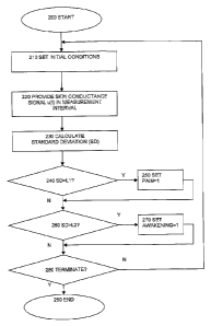
Figure 2 illustrates a flow chart of a method according to the invention.
The method is preferably executed by a processing device in an apparatus for
providing an output signal that reflects the state of the autonomous nervous
system
of a sedated patient, e.g. the processing device 53 in the control unit 5
illustrated in
fig. 1.
The method starts at the initial step 200.
Initial conditions are set in step 210. The initial condition setting step 210
may
include setting a setting a measurement interval and resetting the first 71
and second
72 output signals, i.e. as indicating no pain and no awakening in the patient.
The measurement interval may e.g. be in the range [5 seconds, 40 seconds] or
in the
range [10 seconds, 30 seconds] or about 20 seconds. Other intervals are also
possible.
CA 02718717 2010-09-16
WO 2009/116872 PCT/N02009/000099
7
Next, in the signal providing step 220, a skin conductance signal u(t)
measured at an
area of the patient's skin is provided through the measurement interval. The
signal
may be represented as numeric values stored in a memory, e.g. in the random
access
memory 55, in the apparatus.
Next, in the characteristics calculating step 230, a characteristic of the
skin
conductance signal is calculated, e.g. by the processing device 53. The
calculating
step 230 comprises calculating a value representative of a statistical
dispersion of
the values of the skin conductance signal through the measurement interval.
In an embodiment the calculating step 230 includes calculating a standard
deviation
of the values of the skin conductance signal through the measurement interval.
Alternatively, the calculating step 230 may comprise a statistical function
selected
from the set consisting of:
variance, interquartile range, range, mean difference, median absolute
deviation,
average absolute deviation, coefficient of variation, quartile coefficient of
dispersion, relative mean difference, and variance-to-mean ratio.
For explanatory purposes, it will be assumed in the subsequent detailed
description
that the standard deviation is calculated in step 230. However, the skilled
person
will readily understand that the remaining method steps, and in particular the
establishment of limit values used in those steps, may easily be adapted in
case
another statistical function is used for calculating the statistical
dispersion of the
values of the skin conductance in the calculating step 230.
Next, in the first comparison step 240, the value representative of the
statistical
dispersion of the skin conductance signal, such as the standard deviation, is
compared with a first, predetermined limit value LL
If the statistical dispersion is standard deviation, the first limit value L l
is
advantageously in the range [0.0l S, 0.30gS]. More preferably, the first
limit value
L1 may be in the range [0.02[tS, 0.10 S]. Most preferably the first limit
value L1 is
about 0.03 S.
CA 02718717 2010-09-16
WO 2009/116872 PCT/N02009/000099
8
If another statistical function is used for statistical dispersion,
corresponding ranges
for the first limit value Ll may readily be calculated based on the teachings
of the
present specification.
If the value representing the statistical dispersion (e.g., the standard
deviation)
exceeds the first limit value L1, the first output signal setting step 250 is
performed.
In this step, the first output signal 71 is set as indicating pain or
discomfort in the
patient. Then the method continues at the second comparison step 260.
If the value representing the statistical dispersion does not exceed the first
limit
value L1, the method continues directly at the second comparison step 260.
Next, in the second comparison step 260, the value representative of the
statistical
dispersion of the skin conductance signal, such as the standard deviation, is
compared with a second, predetermined limit value L2.
If the statistical dispersion is standard deviation, the second limit value L2
is
advantageously in the range [0.06 S, 18.0 S]. More preferably, the second
limit
value L2 may be in the range [0.10 S, 3.0[tS]. Most preferably the second
limit
value L2 is about 0.5 S.
If another statistical function is used for statistical dispersion,
corresponding ranges
for second limit value L2 may readily be calculated based on the teachings of
the
present specification.
If the value representing the statistical dispersion (e.g., the standard
deviation)
exceeds the second limit value L2, the second output signal setting step 270
is
performed. In this step, the second output signal 72 is set as indicating
awakening in
the patient. Subsequent to the second output signal step 270 the method
continues at
the terminating decision step 280.
If the value representing the statistical dispersion does not exceed the
second limit,
the method continues directly at the terminating test step 280.
In the terminating test step 280 a test is performed in order to determine if
the
process shall be terminated. The determination may be based on, e.g., a manual
user
input. If the method is decided to terminate, the method terminates at step
290. Else,
the method is repeated from the initial condition setting step 210.
CA 02718717 2010-09-16
WO 2009/116872 PCT/N02009/000099
9
The above description and drawings present a specific embodiment of the
invention.
It will be obvious to the skilled person that numerous alternative or
equivalent
embodiments exist within the scope of the present invention. For instance, the
measurement of skin impedance (including skin resistance) instead of skin
conductance will lead to equivalent results, provided that the inverse nature
of these
variables is taken into account in the subsequent processing of the
measurement
signal.
When the term "patient" is used throughout the specification and claims, is
should
be appreciated that although the present invention is primarily directed
towards the
monitoring of human beings, the invention has also been proven to be
applicable for
monitoring animals, in particular mammals. Consequently, the term "patient"
should be interpreted as covering both human and animal patients.
The inventive concept is not limited to the exemplary embodiments described
above. Rather, the scope of the invention is set forth in the following patent
claims.