Note: Descriptions are shown in the official language in which they were submitted.
CA 02718763 2010-09-16
WO 2009/145834 PCT/US2009/002076
1
BATCH PROCESS AND SYSTEM FOR THE PRODUCTION OF OLEFINS
Related Applications
This application claims priority from U.S. Provisional Application 61/072,993
filed April 4,
2008.
Background
The disclosed embodiments generally relate to processes and systems for
producing
alpha olefins and more particularly to a batch process for the production of
alpha olefins.
A conventional process for production of comonomer grade hexene-1 from C4
raffinate
feed streams is a continuous process that has three stages. First butene-1 is
separated from the
feed stream in a C4 fractionator. The butene-2 in the fractionator bottoms
stream is isomerized to
butene-1 and recycled to the fractionator. Second, the butene-1 is sent to an
autometathesis
reactor to form ethylene and hexene-3. The reactor effluent is sent to a
depentanizer to separate
hexenes. The products are lights that go overhead, the hexene-3 is a liquid
bottoms product, and
the C4/C5 products are recycled. Third, the hexene-3 feed is isomerized and
the hexene-1
product is separated in a C6 fractionator.
US Patent No. 6,727,396 (Gartside, April 2004) describes a continuous process
for
production of hexene-1, combining the isomerization and metathesis steps.
Typical metathesis
reactions are described in US Patent No. 3,595,920 (Ellis et al, July 1971).
US Patent No.
4,709,115 (Jung et al, November, 1987) discusses improving the selectivity and
conversion of
butene-1 and butene-2 to hexene-3 by using catalytic distillation. The removal
of the lighter
components - pushes the reaction equilibrium toward the heavy products. US
Patent No.
5,057,638 (Sweeney, October 1991) discusses a method for production of hexene-
1 from butene-
1 in which the butene-1 is metathesized to hexene-3. Subsequently, a
hydration/dehydration
procedure is applied to produce a mixture of n-hexenes containing hexene-1.
Various other processes are known for the processing of C4 olefins. US Patent
No.
6,875,901 (Gartside et al, April 2005) describes olefin isomerization
technology used for
production of terminal olefins. The process is applied to the production of
butene-1 from butene-
2. US Patent No. 6,777,582 (Gartside et al, August 2004), describes butene-1
autometathesis
technology, including differences from the conventional metathesis reaction of
butene-2 and
ethylene to produce propylene.
Closed-loop heat pumps are used in various processes. US Patent No. 6,589,395
describes a process in which a closed-loop heat pump is included on a general
distillation tower.
This document describes the use of a heat source and heat sink that can be
substituted for the
heat pump should the compressor fail. US Patents No. 5,386,075 (Keil et al,
January 1995) and
No. 4,615,769 (Horigome et al, October 1986) discuss the use of an open-loop
heat pump in an
ethylbenzene/styrene distillation.
CA 02718763 2010-09-16
WO 2009/145834 PCT/US2009/002076
2
It would be useful to develop a process for producing alpha olefins that has
improved
efficiency when operated on a small scale.
Summary
One embodiment is a process for producing an alpha olefin comprising obtaining
a feed
stream comprising an internal olefin having a first carbon number and an alpha
olefin having a
first carbon number, isomerizing the feed stream in a first isomerization
reactor to increase the
quantity of the alpha olefin having the first carbon number, forming a first
isomerization effluent,
fractionating the first isomerization effluent in a first fractionator to
obtain a bottoms stream
comprising the internal olefin having the first carbon number and an overhead
stream comprising
the alpha olefin having the first carbon number, subjecting the overhead
stream to catalytic
metathesis in a metathesis reactor under conditions and in the presence of a
first metathesis
catalyst to produce a mixed olefin effluent comprising an internal olefin
having a second carbon
number and other hydrocarbons, fractionating the mixed olefin effluent in a
second fractionator to
remove at least a portion of the other hydrocarbons and obtain an internal
olefin intermediate,
preparing the first isomerization reactor to receive the internal olefin
intermediate, isomerizing the
internal olefin intermediate in the prepared first isomerization reactor to
form a second
isomerization effluent comprising an increased quantity of alpha olefins
having the second carbon
number, preparing the first fractionator to receive the second isomerization
effluent, and
fractionating the second isomerization effluent in the prepared first
fractionator to separate the
alpha olefin having the second carbon number from the internal olefin having
the second carbon
number. In some embodiments, a portion of the butene-1 is removed from the
first fractionator as
butene-1 product.
Another embodiment is a process for producing hexene-1 comprising obtaining a
C4 feed
containing butene-1 and butene-2, isomerizing butene-2 to butene-1 in a first
isomerization
reactor, forming a first isomerization reactor effluent, fractionating the
first isomerization reactor
effluent in a first fractionator to form an overhead stream comprising butene-
1 and a bottoms
stream comprising butene-2, subjecting at least a portion of the overhead
product to catalytic
metathesis in a first metathesis reactor under conditions and in the presence
of a first metathesis
catalyst to produce a mixed olefin effluent comprising ethylene and hexene-3,
fractionating the
mixed olefin effluent in a second fractionator to form a hexene stream
comprising hexene-3 and
an overhead product stream comprising ethylene, preparing the first
isomerization reactor to
receive the hexene stream, isomerizing the hexene stream to form a second
isomerization
effluent comprising hexene-1 and hexene-2 and the remaining hexene-3,
preparing the first
fractionator to receive the second isomerization effluent, and fractionating
the second
isomerization effluent in the prepared fractionator to obtain a hexene-1
stream.
Yet another embodiment is a system for producing an alpha olefin, comprising a
first
isomerization reactor configured to isomerize a first batch of an olefin
having a first carbon
CA 02718763 2010-09-16
WO 2009/145834 PCT/US2009/002076
3
number to form a first isomerization reactor effluent and subsequently process
a second batch of
an olefin having a second carbon number to form a second isomerization reactor
effluent, a
metathesis reactor positioned downstream from the first isomerization reactor,
the metathesis
reactor being configured to disproportionate the first isomerization reactor
effluent to form a
metathesis reaction product, a first fractionator positioned downstream from
the isomerization
reactor and being configured to separately fractionate the first and second
isomerization reactor
effluents, a second fractionator positioned downstream from the metathesis
reactor to remove
light hydrocarbons from the metathesis reaction product, a storage tank
disposed downstream
from the first or second fractionator, and a storage tank outlet line
connecting the storage tank to
an inlet of the first isomerization reactor and/or to the inlet of the
metathesis reactor.
Brief Description of the Drawings
Fig. 1 is a schematic drawing showing three sections of the system described
herein.
Fig. 2 is a process flow diagram showing a first embodiment.
Fig. 3 is a process flow diagram showing a second embodiment.
Fig. 4 is a process flow diagram showing the first fractionator with a closed
loop heat
pump system capable of operating with both the first isomerization effluent
and the second
isomerization effluent in the process of Fig.3.
Fig. 5 is a graph showing the temperature profile of a C4 fractionator
according to the
embodiment of Example 3.
Fig. 6 is a graph showing the temperature profile of a depentanizer according
to the
embodiment of Example 3.
Fig. 7 is a graph showing the temperature profile of a first C6 fractionator
according to the
embodiment of Example 3.
Fig. 8 is a graph showing the temperature profile of a second C6 fractionator
according to
the embodiment of Example 3.
Detailed Description
The embodiments described herein employ a process operated in a campaign or
sequential processing mode with a single isomerization reactor, a single
superfractionator
following the isomerization, and one or more metathesis reactors with
subsequent fractionation to
obtain intermediate olefins streams, and to obtain a desired olefin product or
products. The
separation of closely boiling double bond isomers of any single carbon number
requires
significant energy and equipment. By using a single superfractionator ( or set
of 2
superfractionators) to separate isomers having a first carbon number in a
first separation process
and to then subsequently use the same superfractionator (or set of
superfractionators) to
separate isomers having a second carbon number in a second separation process,
certain
efficiencies can be realized. Similarly, by using a single isomerization
reactor to isomerize a
CA 02718763 2010-09-16
WO 2009/145834 PCT/US2009/002076
4
compound having a first carbon number in a first isomerization process and a
compound having a
second carbon number in a second isomerization process, processing advantages
will be
achieved. The process can be used with feed streams having carbon chains with
a variety of
carbon numbers to produce product streams having desired carbon numbers. The
process is
particularly useful for producing alpha olefins.
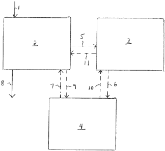
Fig. 1 illustrates a system that includes an isomerization and fractionation
section 2, a
metathesis and fractionation section 3 and a storage section 4. While the
descriptions of Figs. 1-
8 refers to C4 and C6 hydrocarbons, hydrocarbons with other carbon numbers
also can be
processed in the systems that are described. A fractionator / isomerization
reactor combination,
designated as 2 and termed the "superfractionator system", first operates in
C4 service. Mixed
C4's are introduced at 1 and are isomerized and then fractionated at 2 to form
a butene-1
isomerization product. The butene-1 isomerization product is fed continuously
at 5 to the
metathesis and fractionation section 3 in which metathesis takes place. The
metathesis reactor
effluent is fractionated to form light products including ethylene and a
hexene-3 product which is
fed at 6 to a storage tank at 4. When sufficient hexene-3 has accumulated in
the storage tank,
the isomerization and fractionation section 2 is prepared for alternate
service. The hexene-3 from
the tank is then sent at 7 to the isomerization and fractionation section 2
system now in C6
service, where the hexene-3 is isomerized and fractionated to form the hexene-
1 product, which
is removed at 8.
In another configuration, the mixed C4's are processed in the isomerization
and
fractionation system 2 to form butene-1. The butene-1 stream is sent at 9 to
the storage section
4. When sufficient butene-1 has accumulated, the isomerization and
fractionation system 2 is
prepared for alternate service. A portion of the butene-1 optionally can be
removed as a product
and the remaining portion is fed at 10 to the metathesis and fractionation
section 3. The
metathesis reactor effluent is fractionated to produce light products
including ethylene and a
hexene-3 stream. The hexene-3 stream is then sent at 11 to the isomerization
and fractionation
section 2 where the hexene-3 is isomerized and the mixed hexene stream
fractionated to form
hexene-1 product, which is removed at 8.
In all embodiments, all or part of the internal olefin stream from the bottom
of the
superfractionator separation may be recycled to the isomerization reactor to
produce more
butene-1 or hexene-1.
In a larger scale conventional, continuous autometathesis process, separate C4
and C6
systems are employed, allowing heat integration between the systems to reduce
utilities. For the
campaign operation systems described herein, an alternate means of reducing
utility costs is
used to achieve savings. More specifically, in certain embodiments, a heat
pump is included in a
campaign system designed to produce olefins such as polymer-grade hexene-1.
The heat pump
provides a heat-integrated fractionator, whereby the tower's condenser and
reboiler share a
common heat transfer fluid. An open-loop heat pump uses the tower overhead
stream as the
CA 02718763 2010-09-16
WO 2009/145834 PCT/US2009/002076
heat transfer fluid. A closed-loop heat pump uses an alternate fluid. The
alternate fluid is chosen
based upon the specific thermodynamic properties to allow for condensing and
reboiling duties to
be achieved within reasonable pressures such that compression duties are
minimized. For
systems operating in campaign mode, the choice of alternate fluid is
especially advantageous
since it must operate to achieve condensing and reboiling duties in the
fractionation of two
different carbon numbers.
Referring to Fig. 2, a process flow diagram for a campaign process for
sequentially
producing butene-1 and hexene-1 is shown. The overall process is designated as
12. One
portion of the equipment is used in C4 service only, a second portion of
equipment is used in C6
service only, and a third set of equipment is shared between both services.
The butene separation system consists of two towers operated with different
pressures to
allow for energy interchange between them to reduce overall utilities. Tower
14 is considered
tower 1 and tower 24 is considered tower 2. Tower 1 operates at a higher
pressure than tower 2.
This allows the temperature of tower 1 overhead condenser 29 to be at a higher
temperature than
tower 2 reboiler. Since heat is removed in the condenser 29 and supplied to a
reboiler 86, these
can be exchanged without separate external heat being required. The key to
this system is to
balance the duties to allow them to be matched. This matching is
conventionally done by
bypassing a side draw from one tower to the other. Optimally however this is
done by splitting
the main feed to the tower with the proportion to each tower adjusted such
that the exchanger
duties can be matched. The main feed from the isomerization section 47 is
split into line 19 to
tower 1 and 27 to tower 2.
A C4 raffinate in feed line 13, which contains butene-1 and butene-2, and
usually also
contains other C4 hydrocarbons, enters the lower end of fractionator 24 in
which butene-1 and
butene-2 are separated. The bottoms line 15 from fractionator 24, which
primarily contains
butene-2, combines with line 25 (line 32 is not used in the C4 processing
phase) to form line 34,
which enters the isomerization reactor loop, described below. The effluent of
this loop in line 47
is split into line 19, which enters the middle of a fractionator 14, and line
27, which enters the
middle of fractionator 24. In fractionator 14 an overhead product of butene-1
is taken in overhead
line 16. The material in line 16 is condensed in a condenser 17, separated
into a reflux line 29 for
the fractionator 14 and a feed line 31 for the fractionator 13, in which
further separation of butene-
1 and butene-2 takes place.
Fractionator bottoms line 25 is removed from the bottom of the fractionator 14
and
combined with line 15 as indicated above. ,A fractionator reboiler line 20
removes material at the
bottom of the fractionator 14. A purge line 18 is taken off the fractionator
reboiler line 20 to
prevent buildup of any heavy hydrocarbons in the tower bottoms. The remainder
of the
fractionator bottoms in line 21 are reboiled in reboiler 23 and returned to
fractionator 14 where
they undergo separation.
CA 02718763 2010-09-16
WO 2009/145834 PCT/US2009/002076
6
Feed line 31 enters the fractionator 13 above the point of entry of feed line
27. Butene-1
is removed from the top of fractionator 13 in line 33 and butene-2 is removed
from the bottom of
fractionator 13 in line 37. The top line 33 is condensed in a condenser 39 and
is divided into a
reflux line 35 and line 48.
In the isomerization loop, the material in isomerization line 34 is vaporized
in heat
exchanger 36 and heated in heat exchanger 38 and then fed to a furnace 40.
Vaporized line 42
from the furnace 40 is fed to an isomerization reactor 44 in which some of the
butene-2 is
isomerized to form butene-1. The C4 effluent from the reactor 44 leaves at
butene-1 / butene-2
equilibrium. The reactor temperature defines the equilibrium and thus controls
the composition.
The reactor effluent line 47 is cooled in heat exchanger 38 and sent to the
fractionator 14. It is
apparent to one skilled in the art that if the C4 feed line 13 contains butene-
1 above the
equilibrium level set by the isomerization reactor conditions, the feed line
would be first sent to
the tower 14 and the butene-1 content recovered overhead with the butene-2
being fed to the
isomerization reactor 44. Alternately if the composition of C4 feed line 13
had little or no 1
butene, it could first be fed directly to the isomerization system.
Downstream from fractionator 24, the contents of line 48 are either sent to
tank 41, or to
another storage tank, where they are collected until ready for metathesis, or
they are sent directly
to the metathesis section for further processing, in which case tank 41 is not
required. In Fig. 2,
line 48 is shown as providing for flow both into and out of the storage tank
41. When metathesis
is to take place, line 48 is combined with a recycle line 56 containing C4/C5
to form an
autometathesis feed line 58, which is fed to an autometathesis reactor 52.
Before metathesis,
line 58 is vaporized in a heat exchanger 60, further heated in a heat
exchanger 62, and then
heated to reaction temperature in an autometathesis furnace 64. The contents
of line 58 are then
fed to the autometathesis reactor 52. Autometathesis is an equilibrium
reaction in which hexene-
3 is produced. Small amounts of side products propylene, pentene-2, 2-methyl-
pentene-2, and
some C7s also are produced. In addition, a small amount of reverse
isomerization of butene-1 to
butene-2 occurs. Of these side products only 2-methyl-pentene-2, formed from
the reaction of
butene-1 with isobutylene, unfavorably affects the hexene-1 product purity
because it boils lower
than hexene-1 and is thus carried out with the overhead product of the final
C6 separation. Thus,
the isobutylene content in the C4 raffinate feed is required to be minimized
to a level consistent
with the desired hexene-1 specification.
The autometathesis effluent in line 65 is a mixture of Cgs through C7s. The
contents of
line 65 are cooled in heat exchanger 62 to form a depentenizer feed line,
which is sent to a
fractionator 70 (operating here as a depentenizer). A C2/C3 overhead line 71
is removed from the
fractionator 70. The overhead line 71 is condensed in a condenser 74 and
divided into a reflux
line 73 and a feed line 75 for a fractionator 77, which is operated here as a
depropylenizer. The
bottoms line 83 of fractionator 70 is sent to a C6 storage tank 84 where it is
held until the
fractionation and isomerization equipment is ready for C6 processing, or, if
the equipment is
CA 02718763 2010-09-16
WO 2009/145834 PCT/US2009/002076
7
ready, the bottoms line 83 proceeds directly to the fractionation and
isomerization section as line
32 and tank 84 is not required. It is noted that one of the fractionators 13
and 14 can be run as
the depentenizer 70 if the C4 is stored at an appropriate time to allow for
reconfiguration of the
fractionator. Alternately fractionator 70 can be configured through piping to
add additional
fractionation stages to fractionators 14 and 24 thus providing additional
flexibility for processing
and capital and energy savings by allowing fractionators 14 and 24 to be
slightly smaller.
The top line 79 from the fractionator 77 is divided into a C2/C3 line 80,
which is sent to a
steam cracker separation system, for example, and a reflux line 81. Line 82 is
a side draw
product line that is optionally installed to allow for recovery of a higher
purity 1 butene stream
from the unreacted 1 butene. A side draw 85 is removed and passed through a
cooler to partially
condense the vapor stream in the tower at that point when it is reintroduced.
By cooling at a
temperature consistent with cooling water at this point, the refrigeration
commonly used in the
overhead condenser can be reduced. The bottoms line 56 from the fractionator
77 contains C4
and C5 compounds and is combined with line 48 to form the metathesis feed
stream.
Either before metathesis (but after C4 isomerization and fractionation) or
after production
of a sufficient amount of hexene-3, the isomerization reactor 44 and
fractionators 24 and 14 are
prepared for C6 service. The autometathesis reactor is not used in the second
campaign if it was
used in the first step to produce 3-hexene. The hexene-3 is fed from storage
tank 84 in line 32.
Line 32 becomes isomerization feed line 34. Line 34 is vaporized in heat
exchanger 36, heated
in heat exchanger 38, further heated in furnace 40, and fed as line 42 first
to the isomerization
reactor 44. The reactor effluent in line 47 is sent to the fractionators 13
and 14. The isomerization
reactor 44, fractionator 24 and fractionator 14 are now operating in C6
service.
In C6 service, the fractionator 14 bottoms line 20 of C7+ is partially purged
from the
system in line 18, and the remainder is reboiled in reboiler 23 and returned
to the fractionator as
line 21. A side draw 25 of hexene-2 and hexene-3 is taken from a lower stage
of the fractionator
14 (with the top defined as stage 1), combined with bottoms line 15 from
fractionator 24, partially
purged in line 28, and partially recycled to the isomerization reactor 44 in
line 30. Line 30
combines with fresh hexene-3 feed 32 from the C6 storage tank 84 to form
isomerization reactor
feed 34 (now operating in C6 service). The overhead line 16 from fractionator
14 is divided into a
reflux line 29 and a feed line 31 for the fractionator 24.
In the fractionator 24, hexene-1 is taken as overhead product in line 33. Line
33 is
divided into reflux line 35 and line 48. Line 48 contains the hexene-1 product
and is sent to tank
41. It is noted that the metathesis reactor is not involved in the processing
of the C6 line.
As indicated above, the shared equipment from the batch process flowsheet is
designed
for operation in both C4 and C6 service. Depending on the type of equipment,
this can be handled
in different ways. Heat exchangers, for example, may have varying temperature
approaches, but
the heat exchanger surface area may be adjusted by using multiple shells.
Reactor capacity can
be addressed by using multiple reactors. Because the fractionator towers
cannot be handled in
CA 02718763 2010-09-16
WO 2009/145834 PCT/US2009/002076
8
the same way as the heat exchangers or reactors, their design is chosen to
remain fixed between
services.
In order to use the same tower or towers as both the C4 and C6 fractionator,
and if the
second tower is used as both the depentanizer and as part of a C6
fractionator, the tower sizing
must be identical for the chosen flow rates. Because campaign operation allows
for independent
variation of the flow rates between C4 and C6 service, operating time can be
used as a variable to
adjust the flow rates such that a net yearly production of, e.g., 5 KTA hexene-
1 is achieved.
Using this approach, in one embodiment the C4 process is operated for 2,000
hours and then the
C6 process is operated for 5,333 hours.
Overall, the shared use of the fractionator and isomerization system
components in the
batch process eliminates 35 of the 64 pieces of equipment from the continuous
hexene-1
process. The continuous process has 2 complete superfractionator /
isomerization reactor
systems compared to just one for the campaign operation. The estimated
reduction in total
installed capital cost is about 35-45%. This makes campaign operation
especially suited for
smaller capacity installations. An example of a process using the
configuration of Fig. 1 is
provided below as Example 1.
Referring to Fig. 3, a process flow diagram for another campaign process for
sequentially
producing butene-1 and hexene-1 is shown. The overall process is designated as
110. One
portion of the equipment is used in C4 service only, a second portion of
equipment is used in C6
service only, and a third set of equipment is shared between both services.
A C4 raffinate in feed line 112, which contains butene-1 and butene-2, and
usually also
contains other C4 hydrocarbons, combines with the contents of line 134 and
enters the
isomerization reactor loop. The effluent of this loop in line 147 enters the
middle of a fractionator
114. In fractionator 114 an overhead product of butene-1 is taken in overhead
line 116. The
contents of line 116 are condensed in a condenser 117.
Fractionator bottoms in line 122 are removed from the bottom of the
fractionator 114,
partially purged in a purge line 128, and the remaining material in line 130
is combined with the
contents of C4 feed line 112 (line 132 is not in use during the C4 phase) to
form isomerization feed
line 134. Purge line 128 is provided to remove any n-butanes in the C4 feed
112 that would
accumulate in the system. A fractionator reboiler line 120 removes material at
the bottom of the
fractionator 114. A purge line 118 is taken off the fractionator reboiler line
120 to prevent buildup
of any heavy hydrocarbons in the tower bottoms. The remainder of the
fractionator bottoms in
line 121 is reboiled in reboiler 123 and returned to fractionator 114 where it
undergoes
separation.
The contents of isomerization line 134 are vaporized in heat exchanger 136 and
heated
in heat exchanger 138 and then fed to a furnace 140. Vaporized material in
line 142 from the
furnace 140 is fed to an isomerization reactor 144, which in one embodiment is
an equilibrium
reactor operating at 343 C and 2978 kPa. The C4 effluent from the reactor in
this embodiment
CA 02718763 2010-09-16
WO 2009/145834 PCT/US2009/002076
9
leaves at butene-1 / butene-2 equilibrium with an approximate butene-1
concentration of 21%.
The reactor effluent in line 147 is cooled in heat exchanger 138 and sent to
the fractionator 114.
The ratio of recycle to fresh feed in the fractionator is typically 2.4 to 1.
It is apparent to those
skilled in the art that if the C4 feed in line 112 contains butene-1 above the
equilibrium level set by
the isomerization reactor conditions, the feed stream would be first sent to
the tower 114 and the
butene-1 content recovered overhead with the butene-2 being fed to the
isomerization reactor
144.
The butene-1 product from the fractionator 114 in overhead line 116 is divided
into a
reflux stream in line 119 and intermediate product in line 148. The material
in line 148 is sent
into line 150 (line 154 is used for C6 processing). The butene-1 in line 150
is combined with a
recycle line 156 containing C4/C5 to form an autometathesis feed line 158,
which is fed to an
autometathesis reactor 152. The material in line 158 is vaporized in a heat
exchanger 160,
further heated in a heat exchanger 162, and then heated to reaction
temperature in an
autometathesis furnace 164. Vaporized material in line 159 is then fed to the
autometathesis
reactor 152. Autometathesis is an equilibrium reaction
The autometathesis effluent in line 166 is a mixture of Cgs through C7s. The
material in
line 166 is cooled in heat exchanger 162 to form a (depentenizer) feed line.
The contents of line
170 are sent to a fractionator 168 (operating here as a depentenizer), which
in one embodiment
operates at 1200 kPa with 30 theoretical stages and a reflux ratio of 1Ø The
temperature in the
fractionator 168 typically is in the range of 60-100 C. A C2/C3 overhead line
171 is removed from
the fractionator 168. Overhead line 171 is split into line 172 and line 173.
The contents of
overhead line 172 are cooled in heat exchanger 174 and sent to a flash drum
176. The light
fraction from the flash drum comprising ethylene and propylene are purged in
line 178 and can be
recycled to the ethylene/propylene recovery section of an ethylene cracker.
The Cos-C5s from the
bottoms of the flash drum in line 156 still contain a significant amount of
butene-1 and are
recycled in line 156, which is combined with line 150 to form line 158, the
feed line for the
autometathesis reactor. The material in overhead line 173, when operating in
C4 mode, is
condensed in a condenser 174 to form reflux for tower 168.
The fractionator bottoms line 180, separated to 98 mol% hexene-3, is divided
into a
hexene-3 line 182, a reboiler line 183, and a C6 recycle line 188. In C4
operating mode, the
hexene-3 in line 182 fills a C6 storage tank 184 and is used as the feed for
the second phase of
the campaign operation.
After production of a sufficient amount of hexene-3, the system is shut down
and
prepared for operation in C6 service. The isomerization reactor 144, tower 114
and tower 168 are
prepared for C6 service. The autometathesis reactor is not used in the second
campaign. The
hexene-3 is fed from storage tank 184 in line 132. Line 132 becomes
isomerization feed line 134.
Material in line 134 is vaporized in heat exchanger 136 and heated in heat
exchanger 138, then
further heated in furnace 140, and fed as line 142 first to the isomerization
reactor 144. In the
CA 02718763 2010-09-16
WO 2009/145834 PCT/US2009/002076
isomerization reactor 144, approximately 8.9% conversion to hexene-1 occurs.
The reactor
effluent in line 147 is sent to the fractionator 114. Both the isomerization
reactor 144 and
fractionator 114 are now operating in C6 service.
To make the campaign system work, the fractionation and isomerization
equipment must
be identical for C4 and C6 processing. The separation of the hexene-1 from the
mixed hexene
stream requires more fractionation than the separation of butene-1 from the
butene-1 / butene-2
stream in C4 operation. One option is to design a tower oversized for C4
operation but that will be
appropriate for C6 service. Another option is to use tower 168 to provide the
additional
fractionation capacity for C6 operation since the autometathesis reactor is
not used in C6
operation. In this embodiment, tower 168 is used as the top portion of the C6
fractionation
receiving the overhead from tower 114.
The fractionator 114 bottoms stream of C7+ in line 118 is purged from the
system. A side
draw 122 of hexene-2 and hexene-3 is taken from a low stage of the
fractionator 114 (with the top
defined as stage 1) and recycled to the isomerization reactor 144 via lines
126 and 130. It is
mixed with fresh hexene-3 feed 132 from the C6 storage tank 184 to form
isomerization reactor
feed 134' (now operating in C6 service). Purge line 128 is not in service. The
overhead line 116
is separated to a desired ratio of hexene-1 and most of it is sent in line 148
to line 154 and then
line 170 to fractionator 168 (formerly functioning as a depentenizer for C4
service). It is noted that
the metathesis reactor is not involved in the processing of the C6 line.
In the fractionator 168, comonomer grade hexene-1 (98.5 mol%) is taken as
overhead
product in line 171. There is no flow through line 172 and separator 176 is
not in C6 service. The
hexene-1 product is removed in line 173, and a reflux line 175 returns to the
tower with the
hexene-1 product being removed in line 181. The bottoms hexene-2 and hexene-3
from tower
168 are recycled to the isomerization section in line 188. The contents of
bottoms line 188 is
mixed with the other hexene-2 / hexene-3 recycle in line 122 from tower 114 to
form line 126. The
fractionator 168 operates at an overhead pressure of 50 kPa. Temperature
profiles for the C6
fractionation in fractionator 114 and fractionator 168 are shown in Figs. 5
and 6, respectively.
As indicated above, the shared equipment from the batch process flowsheet is
designed
for operation in both C4 and C6 service. Depending on the type of equipment,
this can be handled
in different ways. Heat exchangers, for example, may have varying temperature
approaches, but
the heat exchanger surface area may be adjusted by using multiple shells.
Reactors can be
addressed by using multiple reactors. Because the fractionator towers cannot
be handled in the
same way as the heat exchangers or reactors, their design is chosen to remain
fixed between
services.
In order to use the same tower as both the C4 and C6 fractionator and to use
the second
tower as both the depentanizer and the C6 fractionator, the tower sizing must
be identical for the
chosen flow rates. Because campaign operation allows for independent variation
of the flow
rates between C4 and C6 service, operating time can be used as a variable to
adjust the flow
CA 02718763 2010-09-16
WO 2009/145834 PCT/US2009/002076
11
rates such that a net yearly production of, e.g., 5 KTA hexene-1 is achieved.
Using this
approach, in one embodiment the C4 process is operated for 2,000 hours to
produce 2,696 kg/h
hexene-3. 500 hours of downtime is provided to empty the fractionators and
reactors in
preparation for the C6 run. Then, the C6 process is operated for 5,333 hours,
feeding 1,010 kg/h
hexene-3 to produce 937 kg/h hexene-1. An additional 500 hours is allowed for
the transition
back to C4 service. Operation at these flow rates yields the same tower
diameter after choosing
100 theoretical stages for the C4/C6 fractionator, and likewise for 30 stages
in the depentanizer/C6
fractionator. An example of a process using the configuration of Fig. 2 is
provided below as
Example 2.
Overall, the shared use of the fractionator and isomerization system
components in the
batch process eliminates 35 of the 64 pieces of equipment from the continuous
hexene-1
process. The continuous process has 2 complete superfractionator /
isomerization reactor
systems compared to just one for the campaign operation. The estimated
reduction in total
installed capital cost is about 35-45%. This makes campaign operation
especially suited for
smaller capacity installations.
Referring now to Fig. 4, an embodiment is shown in which a closed-loop heat
pump is
used to even further improve the efficiency of the campaign process depicted
in Fig. 3. The
overall system is designated as 200. This system uses changes in pressure to
adjust the boiling
point of a heat transfer fluid within the temperature ranges of a
fractionator's reboiler and
condenser so that the fluid can be alternately condensed and vaporized,
respectively, thus
providing heat integration in place of conventional utilities such as
refrigeration for condensing or
steam for reboiler. The heat pump is associated with the fractionator 214. (A
top line 216 and a
bottoms line 220 are removed from the fractionator 214). The fluid begins the
cycle as a vapor in
vapor line 202. Vapor line 202 is compressed in a compressor 204 to a pressure
where the
temperature at which the vapor condenses is above the temperature of the
reboiler 206.
Compressed line 202 is divided into line 208 and line 210 and the two lines
are recombined as
line 212. Line 210 is cooled in a heat exchanger 213. The use of cooling water
exchanger 213
allows for control of the duty in reboiler 206 by controlling the temperature
and/or flow of the hot
higher pressure vapor. In some cases the contents of line 210 are condensed in
exchanger 213
and a 2 phase mixture fed to reboiler 206. This effectively limits the amount
of heat transfer fluid
that is condensed in the reboiler and thus the heat transferred to the
reboiler. Line 212 is
condensed in the reboiler 206. Controller 236 determines the split between
lines 208 and 210.
Line 212 is now in liquid phase.
At this point in the cycle the hot duty requirement of the reboiler is
satisfied. The system
must now satisfy the lower temperature duty of the tower condenser. Liquid in
line 212 is let down
in an expansion, controlled by the overhead vapor from expansion drum 122 to
drop the boiling
point below the temperature of the fractionator condenser 224. This reduces
the temperature of
the line as a portion of 212 is vaporized at the lower pressure. Line 212 is
then combined with
CA 02718763 2010-09-16
WO 2009/145834 PCT/US2009/002076
12
(optional) line 215 as line 216. Optionally, as described below, line 216 is
cooled in heat
exchanger 218 using cooling water line 220. Vapor is removed from drum 222 as
line 228. Vapor
is not sent to the condenser 224. The liquid is removed from drum 222 in line
226. Line 226 is
then vaporized in the condenser 224 and after vaporization is combined with
line 228 to form line
230. Line 230 passes through a knockout drum 232. The vapor in drum 232 is
removed as line
202, which as mentioned above, is returned back to the compressor 204. Any
small amount of
liquid in drum 232 is removed in line 215, which is combined with the effluent
from the expander
240 to form line 217.
To settle any difference in condenser and reboiler duty, an additional
exchanger may be
required within the loop to add or remove heat as necessary. In this
particular campaign system,
the condenser duty is greater than that of the reboiler, so heat exchanger 213
is placed at the
compressor discharge in parallel with the reboiler to remove the difference in
heat duty, allowing
the heat pump fluid to fully condense in the reboiler 206. Heat exchanger 213
is the exchanger to
remove "extra" duty from the loop based on the reboiler-condenser duty
difference. Conversely,
if the reboiler duty were greater, a heat exchanger 238 operated with steam
instead of cooling
water would be placed at the outlet of the expander 240 to have more of the
fluid as vapor to
separator 222 and thus feed lower amount of liquid as line 226 to vaporize in
the condenser.
To avoid temperature crosses in the reboiler and condenser, a temperature
difference of,
e.g., 3 C can be used between the outlet temperatures of the process fluid,
line 220 for example,
and the heat pump, line 212. The compressor and expander discharge pressures
can be
considered fixed, set by the requirement to bring the heat pump fluid boiling
point within the
approach to the reboiler and condenser temperatures, respectively.
Effectively, the work
performed by the compressor is that required to undo the work of the expander,
so the energy
costs of the heat pump decrease as the temperature spread across the tower
becomes smaller.
With the pressures in each portion of the heat pump cycle fixed and the
condenser as the
controlling duty, the inlet temperature to the condenser can be maximized in
order to provide
additional cooling capacity. In this case the cooling water heat exchanger 218
is used in the loop
at the outlet of the expander to cool the line before entering the condenser
224. This is a low-
cost method of reducing the circulation rate through the higher-cost
compressor 204.
The working fluid for the heat pump used in a campaign mode of processing
typically is a
hydrocarbon or mixture of hydrocarbons such that the boiling point of that
hydrocarbon or mixture
falls between the boiling point of the first carbon number and the second
carbon number. This
differs from a conventional closed loop heat pump system that is operating on
a single carbon
number. There, the working fluid is selected based upon a single carbon number
and typically
has properties close to the hydrocarbon being separated. In one particular
closed-loop system for
campaign mode operation, n-butane is used as the circulating fluid and the
heat pump is applied
to one or both of the fractionators in the isomerization section operating in
either C4 or C6 service.
N-butane boils between the 1-butene overhead in one mode and the 3-hexene
reboiler in the C6
CA 02718763 2010-09-16
WO 2009/145834 PCT/US2009/002076
13
service mode. Note also it is possible to use a mixture of fluids as the heat
transfer fluid. In that
case it is possible to adjust the composition to optimize the thermodynamic
properties of the fluid
mixture. The energy requirement of the heat pump is that to run the
compressor, significantly less
than the stand-alone tower due to the integration of reboiler and condenser
heat duties. A closed
loop applied to both towers would integrate both reboilers in series within
the loop, then both
condensers in series, adjusting the compressor and expander discharge
pressures accordingly.
Variations in process parameters equipment sizing, etc. will depend upon the
desired
butene-1 purity. Very high purity butene-1 generally is not required to
produce hexene-3 by
autometathesis. The fractionation tower could be designed to produce for
example 95% butene-
1, with one part of the product going to autometathesis for lights, recycle
and hexene-3, and
another part going to a different fractionator to produce high purity butene-1
(polymer grade). In
this case, both the depentanizer of the main example and the additional butene-
1 fractionation
could be used in campaign mode for hexene purification. It is noted that feed
to autometathesis
could.be a tower side draw where overhead is the high purity butene-1.
A number of other methods of isomerization and metathesis can be applied and
still
maintain the important feature of the campaign process, which is shared
equipment between C4
and C6 service. Further, additional processing steps and/or alternate
feedstocks can be used.
One non-limiting example of an alternative process would be to employ an
additional metathesis
reaction step involving the reaction of ethylene with butenes (ethenolysis).
Depending upon the
feed quality to the autometathesis step (the butene-2 content) some propylene
and pentene-2 will
be formed. A second autometathesis step involving the reaction between butene-
1 and pentene-
2 to yield propylene and hexene-3 could be included. This additional
autometathesis step would,
for example, involve line 75 or 82 of Fig. 2. Pentene-2 produced in reactor 52
can be sent to a
second autometathesis reactor to make more hexene-3. A further example would
be to
incorporate the process of US Patent No. 4,709,115 (Jung et al, November
1987), where the
metathesis step occurs in a catalytic distillation tower. In the campaign
system, this variation
would manifest itself as a catalytic depentanizer in C4 service, with the
catalyst replaced by inert
beads to operate as C6 fractionator in C6 service.
The campaign processing scheme described herein also can be integrated with
other
processing units. For example, the campaign process can be integrated with a
continuous
conventional metathesis unit for producing propylene from the reaction of
ethylene and butene-2.
The conventional metathesis process typically feeds ethylene and a mixed C4
raffinate stream
containing butene-2, which can be the same C4 feed raffinate stream as that
used for the process
in Figure 1, to a metathesis reactor. Ethylene and propylene produced in the
autometathesis step
of the campaign operation is then sent to the fractionation system of the
conventional metathesis
unit. This effectively provides feed ethylene to the conventional metathesis
reaction and provides
propylene product. A recycle of C4 is taken from the second separation step
back to the reactor.
To integrate the campaign process in Figure 3, for example, the purge streams
118, 126, and 178
CA 02718763 2010-09-16
WO 2009/145834 PCT/US2009/002076
14
would be recycled to an appropriate disposition in the conventional metathesis
process. Because
this integration can use the same C4 raffinate feed stream, a number of
options are afforded.
One option is that the total C4 raffinate can remain constant, thus converting
some propylene
production in conventional metathesis to hexene-1 production in the campaign
process. A
second option is to maintain constant propylene production from the
conventional metathesis
process and "scale up" up the C4 raffinate flow rate as required for butene-1
or hexene-1
production from the campaign process. Any intermediate combination of product
flow rates from
these options is also possible.
Two significant advantages exist in integrating the campaign process with
conventional
metathesis. First, all purge streams from the campaign process which would
otherwise be lost to
the cracking furnace or another low-value disposition can be recovered in the
conventional
process. In particular, the C2-C3 of stream 78 is ethylene that has been
upgraded from the C4
raffinate feed and greatly reduces the fresh ethylene requirement to the
conventional metathesis
unit. Second, it is possible to make use of the autometathesis reactor of the
campaign process
when it is idle in C6 service. If additional C4 raffinate and ethylene are
available, they can be fed
to the autometathesis reactor during the C6 phase of the campaign process.
Metathesis will
produce additional propylene with no change of catalyst required. The
additional propylene can
be fed to the separation equipment of the conventional metathesis process and
recovered. In this
way, extra propylene production for a portion of the operating year is
possible either to the limit of
the separation equipment overdesign in a retrofit case, or to a desired amount
in the case of a
new integrated plant.
In a second integration example, a process for the production of olefins from
methanol
(MTO) produces a C4-C6 stream composed of linear olefins can be incorporated
upstream.
Similarly, processes that utilize ethylene oligomerization to produce linear
alpha olefins have
alpha olefin streams in even carbon numbers from C4 through C20+ can be
incorporated. The
campaign processing scheme in combination with metathesis can be used to
adjust the carbon
number distribution and thus maximize product value dependent upon market
conditions. For
example, a C,0 alpha olefin can be isomerized to a number of C,0 internal
olefins using the
isomerization step. The internal olefins can be then reacted with ethylene in
a metathesis step to
produce a range of lower carbon number alpha olefins. These can be separated
and processed
in campaign mode or alternately the isomerization/metathesis process used for
a C16 alpha olefin
following operation with a C10 alpha olefin feed.
The particular campaign system described includes two fractionators. One is
used as a
C4 and C6 fractionator and combined with the isomerization reactor. The second
is used as a
depentanizer and second C6 fractionator. In one embodiment, the heat pump is
placed on only
the C4/C6 fractionator, with the depentanizer/C6 fractionator using
conventional utilities. Another
embodiment involves use of a heat pump on the depentanizer/C6 fractionator. In
a further
configuration a single heat pump loop passes through all fractionation towers.
For a campaign
CA 02718763 2010-09-16
WO 2009/145834 PCT/US2009/002076
process, this type of loop would operate on the C4 fractionator and
depentanizer during C4
service, then on both C6 fractionators during C6 service, with possible
sequences of reboiler-
reboiler-condenser-condenser or reboiler-condenser-reboiler-condenser within
the loop. Yet
another configuration places one heat pump loop on each tower.
The embodiment of Figure 2 shows a two-tower system for the fractionator
following the
isomerization system. This embodiment also can include the option of an
integrated
condenser/reboiler, with a heat pump on the "outer" exchangers. In this
configuration, the tower
pressures would be adjusted such that, for example, the condenser of the C4
fractionator could
be integrated with the reboiler of the depentanizer. The heat pump is then
placed across the
wider temperature range of the remaining exchangers. The integrated
condenser/reboiler is
possible with either the upstream or the downstream tower operating as the
higher pressure
tower.
In the embodiments described above in detail, one suitable circulating fluid
to be used in
the heat pump is n-butane. This fluid is useful because its boiling
temperature is within range of
the tower condenser and reboiler at appreciable pressure. Alternative heat
pumps on this type of
system can use a mixture of hydrocarbons or other fluids. Mixtures are
particularly useful to
extend the boiling range of the heat pump fluid for towers with wide
temperature profiles, thus
minimizing the difference between compressor and expander discharge pressures.
Heat pump loops with a constant circulation rate between C4 and C6 service are
possible,
with the compressor and/or expander discharge pressures relaxed to allow the
use of some
sensible heat when in the lower-duty service. A heat pump loop with or without
heat exchanger
118, placed to provide additional cooling capacity at low cost (cooling
water), is also feasible. In
lieu of balancing the condenser and reboiler duties by removing heat in heat
exchanger 113, a
steam exchanger could be placed to add heat in the opposite portion of the
loop.
The heat pump can be expanded to both fractionators of the batch system. This
would
result in heat integration of the condensers and reboilers of the C4
fractionator and depentanizer,
and the two C6 fractionators. There can be a single heat pump loop or two
separate loops having
one heat pump on each tower.
One or more of the above variations may be used with an open-loop heat pump.
An
open-loop heat pump uses the tower overhead stream as the heat exchange fluid
against the
bottoms stream.
In another embodiment the pressures of the two fractionators can be adjusted
such that,
for example, the condenser of the C4 fractionator is heat-integrated with the
reboiler of the
depentanizer. A heat pump can then be used on the reboiler of the C4
fractionator and
condenser of the depentenizer.
Some or all of the heat pump configurations described above may be employed
using a
mixture of fluids in the heat pump loop, which would provide a broader region
of
vaporization/condensing than a pure fluid. The required difference between
compressor and
CA 02718763 2010-09-16
WO 2009/145834 PCT/US2009/002076
16
expander discharge pressures, thus the compressor energy consumption, would be
decreased.
The batch system also presents the possibility of different fluids in the heat
pump loop between
C4 and C6 service, or a different fluid for each loop if two loops are used.
The following examples are included to illustrate certain features of the
disclosed
embodiments but are not intended to limit the scope of the description.
Example 1 - Campaign Autometathesis Process Employing High-Selectivity W03
Catalyst and an Integrated Two Tower Fractionation System
A computerized simulation was conducted in which butene isomerization and
autometathesis sections are operated as one unit, temporarily storing n-C6
made in the
autometathesis section in a process having the configuration shown in Fig. 2
with storage tank 84
being used but not 41. This was followed by C6 isomerization operation
utilizing the equipment
used in the butene isomerization section. In this scheme, the entire set of C6
isomerization
equipment is avoided to reduce capital cost. In this Example, 5 KTA of polymer
grade 1 -hexene
was produced in a campaign process. The butene feed used in shown in table 1
below.
Table 1 - C4 Feed to Autometathesis Process
Component Wt %
Iso-butane 4.0
n-butane 16.1
tr2-butene 18.2
1-butene 50.5
iso-butene 0.10
cis2-butene 11.1
Total 100.0
Flow Rate, Kg/H 14,900
In the campaign operation simulation, C4 isomerization and autometathesis
sections were
operated for 2000 hours producing 3-hexene, which was temporarily stored in a
storage tank for
further isomerization to 1 -hexene. After producing the 3-hexene for 2000
hours, C4 isomerization
and autometathesis operation were shut down and the distillation towers and
reactors were
emptied. The C6 isomerization section was then operated for 5333 hours
producing 1-hexene
from the stored 3-hexene, utilizing the same equipment used in C4
isomerization operation.
Eliminating the C6 isomerization equipment reduces capital cost. The
particular hours of
operations were chosen such that the interchangeability of the equipment was
possible providing
for a net yearly production of 5000 KTA of 1 -hexene.
This process followed the same scheme as would be used in a continuous
autometathesis process. The separation of 1 -hexene from its isomers was the
critical separation.
In the continuous process, a two-tower design is used for this separation. The
same two-tower
CA 02718763 2010-09-16
WO 2009/145834 PCT/US2009/002076
17
separation system was used in the batch process for separation of 1 -hexene
from other C6
compounds. Since this equipment was used in the butene isomerization, the same
two-tower
separation system applies to separation of 1-butene from 2-butene as well.
The raffinate II feed composition is given in Table 1. The 1 -butene content
in the C4 feed
is higher than the equilibrium butene ratio at 650 F, the operating
temperature of the C4
isomerization reactor (feed B1/B2 = 2.8, equilibrium 131 /132 at 650 F =
0.28). Hence the raffinate II
feed was sent to the C4 separation tower system to separate 1 -butene prior to
entering the
butene isomerization reactor.
The bottom product from the C4 separation contained mainly 2-butenes and n-
butane.
This bottom product stream was recycled to the isomerization reactor to
increase n-butene
utilization. A small purge was removed from this recycle stream to control the
build-up of the
inerts, n-butane and iso-butane. The isomerization reactor feed exchanged heat
with the hot
reactor product. The reactor feed was further heated to the reaction
temperature inside a fuel-
fired furnace and entered the reactor. The reactor was operated at 650 Deg. F
and 117 psia. The
catalyst was MgO tablets. Feed ratios and 2-butene conversion data for the
isomerization reactor
are shown below on Table 2. The reaction product was sent to the butene
separation system.
The C4 isomerization reactor and separation tower were used during the C6
isomerization
operation as well.
The C4 separation system consisted of a two tower system. The condenser of one
tower
is used to reboil the second tower. The two towers are operated at different
pressures to allow
for this exchange. Splitting the feed with a portion to each tower reduces
energy consumption
while balancing the duties for each tower. The first fractionator had 80
stages and second
fractionator had 70 stages. The raffinate II feed entered second tower at
stage 24. The butene
isomerization reactor product was split. One portion entered the first tower
at stage 15 and other
portion entered the second tower at stage 48. The distillate product from
first tower, concentrated
in 1 -butene entered the second tower at stage 30. By adjusting the vapor feed
split ratio and
operating pressures of the towers, energy exchange between the tower 1
condenser and tower 2
re-boiler was made possible. The final distillate product was 90 mol% 1 -
butene, which was sent
to the autometathesis section for further processing. The 1 -butene product
stream contained iso-
butane (5.1 wt%), n-butane (3.8 wt%), tr2-butene (1.2 wt%) and iso-butene
(0.13 wt%). If
required, monomer grade 1-butene (99 wt%) could also be produced from this
separation system.
Details of the separation tower are given in Table 5 below.
In the second processing step but still operating in the C4 mode, 1 -butene
from the
butene isomerization / separation system was sent to the autometathesis
section to produce n-
hexenes. In this section, 1-butene feed was mixed with recycled 1-butene from
the separators
and exchanged heat with the hot reactor product. The reactor feed was further
heated to the
reaction temperature inside a fuel-fired furnace and entered the reactor. The
autometathesis
reactor operated at 600 F and 275 psia. The catalyst was W03 on high-purity
silica. Inside this
CA 02718763 2010-09-16
WO 2009/145834 PCT/US2009/002076
18
reactor, 1-butene reacted with itself to produce ethylene and 3-hexene. Side
reactions between 1-
butene and 2-butenes producing propylene and 2-pentenes also occurred.
Moreover, isobutylene
reacted with 1 -butene to produce ethylene and 2-methyl-2-pentene (i-C6
olefin, BP=67.3 deg C).
The other possible isobutylene reactions were determined to be insignificant.
The production of i-
C6 olefin in the autometathesis reactor is undesirable since it affects the
purity of 1 -hexene
product. Hence the isobutylene content in the raffinate II feed was kept very
low. A small amount
of C7 and C8 was also produced by other metathesis reactions. Recycle,
conversion, and
reaction product composition data are shown on Table 3.
The autometathesis reaction products were separated in the depentenizer. The 3-
hexene was recovered in the depentenizer tower as bottom product and sent to
the storage tank
for use in the C6 mode step of the campaign process. The i-C6 olefins, C7 and
C8 produced
inside the autometathesis reactor were also carried along with the 3-hexene.
The distillate from
the depentanizer was sent to the depropenizer for further separation. The
lighter components,
ethylene and propylene were recovered as distillate and sent to product
recovery in the ethylene
plant. The unconverted 1 -butene was recovered as the bottom product and
recycled to the
autometathesis reactor to improve butene utilization. A side-draw stream was
purged from the
depropylenizer to remove the inerts, iso-butane and n-butane from the
autometathesis system.
The details of the separation tower are shown below.
At the completion of the C4 isomerization and autometathesis run, the process
was shut
down. The reactors and distillation towers were emptied in preparation for the
C6 isomerization
run. The C6 isomerization operation was then conducted as shown in the process
flow diagram.
The hexene isomerization section consisted of a hexene isomerization reactor
and
hexene separation system, and the same equipment as was used for C4 processing
was
employed. The 3-hexene from the storage tank was mixed with recycled 2-hexenes
and 3-
hexenes from the C6 separation system and exchanged heat with the hot
isomerization reactor
product. The isomerization reactor feed was further heated to the reaction
temperature inside a
fuel-fired furnace and entered the reactor. The reactor operated at 650 F and
56 psia. The
catalyst was MgO tablets. The reactor product was an equilibrium mixture of 1 -
hexene, 2-
hexenes and 3-hexenes including the cis-trans isomers. This product mixture
was separated in
the hexene separation system to produce polymer grade 1 -hexene as distillate
product. (The two-
tower separation system with energy integration was explained previously.) The
bottom product,
2-hexenes and 3-hexenes were recycled to the isomerization reactor. A small
purge was taken
from the separation system to remove the heavy components from the C6
isomerization system.
The details of the separation tower are given below in Table 6.
The 2-methyl-2-pentene from the autometathesis reactor was also carried over
to the
hexene isomerization section where the isomerization activity of the MgO
catalyst produced its
isomers: 2-methyl-1 -pentene, 4-methyl-1 -pentene, 4-methyl-cis-2-pentene and
4-methyl-trans-2-
CA 02718763 2010-09-16
WO 2009/145834 PCT/US2009/002076
19
pentene. Since the boiling point of all i-C6 except the 2-methyl-2-pentene are
lower than 1 -
hexene, any i-C6 produced in the autometathesis reactor ends up with the 1 -
hexene product.
Table 2 - Butene Isomerization Reactor
Rx Operating Temp, F 650
Rx Operating Pr, Psia 117
Catalyst MgO tablets
Rx Feed B2/B1 ratio 49
Rx Prod B2/B1 ratio 3.6
2-Butene conversion, % 21.7
Table 3 - Autometathesis Reactor
Rx Operating Temp, F 600
Rx Operating Pr, Psia 275
Catalyst WO3 on high purity
silica
Rx Feed B1/B2 ratio 96.2
B1 Conversion, mol% 46.2
Molar Selectivity, %
Ethylene 40.53
Propylene 12.22
Pentene 0.02
n-hexene 46.48
i-hexene 0.15
C7 and C8 0.60
The autometathesis reactor performance was based on experimental data for high
selectivity WO3 catalyst. This information was incorporated into the HYSYS
simulation. The
conversion and selectivity were determined for the autometathesis reactor feed
given in Table 10.
The autometathesis selectivity for the main reaction (C2+C6) was 87.01. The
selectivity for the
side reactions (C3+C5) was 12.37. The selectivity for the isobutylene reaction
with 1 -butene was
0.15. A small amount of C7 and C8 was also formed in the autometathesis
reactor.
Table 4 - Hexene Isomerization Reactor
Rx Operating Temp, F 650
Rx Operating Pr, Psia 56
Catalyst MgO tablets
CA 02718763 2010-09-16
WO 2009/145834 PCT/US2009/002076
Rx Feed (2-hex+3-hex)/1-hex ratio 63.36
Rx Prod (2-hex+3-hex)/1-hex ratio 10.6
1-Hex Prod Composition, mol% 8.3
The C6 isomerization reactor performance was obtained from the correlation of
experimental data. This correlation was incorporated into the HYSYS
simulation.
Table 5 - Specifications of the Separation Columns in C4 Isomerization and
Autometathesis
Parameter Depropenizer Depentenizer Butene Butene
Splitterl Splitter2
Number of Stages 15 40 80 70
Feed Tray (# from 5 20 15 24,30,48
top)
condenser P, Kpa 2200 1600 700 530
re-boiler P, Kpa 2300 1800 750 550
Top Spec 1.5 mol % 1-C4 in distillate 0.1 mol% n-C6 40 mol% 1- 90 mol% 1-
in distillate butene in butene in
distillate distillate
Bottom Spec 0.5% propylene in bottom 0.01 mol% n- 0.5 mol% 1 mol% 1-
C5 in bottom 1 -butene in butene in
product bottom bottom prod
product
Other Specs Top vent =15 kmol/h
Side draw= 23 kmol/h
Interstage cooling at stage 3
= 1000 KW
Note Bottom
product is 98.5
wt% n-C6
CA 02718763 2010-09-16
WO 2009/145834 PCT/US2009/002076
21
Table 6 - Specifications of the separation columns in C6 isomerization
Parameter C6 C6
Splitterl Splitter2
Number of Stages 80 70
Feed Tray (# from 25 40,60
top)
condenser P, Kpa 207 117
re-boiler P, Kpa 241 138
Top Spec 60 mol% 2&3 1.2 mol% 2&3
hexene in hexene in distillate
distillate
Bottom Spec 1 mol% 1-hexene 2.5 mol% 1-
in side-draw hexene in bottom
product prod
Other Specs 45 mol% C7 &
C8 in bottom
product
Note Side-draw from
stage 74
The material balance for the batch case, producing 5 KTA of polymer grade 1 -
hexene is
given below. The material balance summary as well compositions of key streams
are given in the
following tables.
Table 7 - Overall material balance for C4 Isomerization and Autometathesis
(2000 hours
operation)
MTA
Feed
C4 Feed 12,000
Total Feed 12,000
Products
C2/C3 to cracker 1,852
Depropenizer side draw 2,120
C4 purge 2,637
Depentenizer Bottom 5,391
Total Products 12,000
CA 02718763 2010-09-16
WO 2009/145834 PCT/US2009/002076
22
Table 8 - Overall material balance for C6 Isomerization (5333 hours operation)
MTA
Feed
C6 Feed 5,391
Total Feed 5,391
Products
Hexane-1 Prod 5,026
C6 purge 205
C6+ Purge 160
Total Products 5,391
Table 9 - Material balance for the butene isomerization section (2000 hours
operation)
Component, C4 C4 C4 C4 C4 131 to
wt% Feed recycle Isomerization Isomerization Purge Autometathesis
Feed Prod
Iso-butane 4.04 0.0 0.0 0.0 0.0 5.2
n-butane 16.14 61.3 61.3 61.3 61.3 3.5
Tr2-butene 18.17 22.6 22.6 17.8 22.6 1.3
1-butene 50.45 0.70 0.70 8.5 0.70 89.7
Iso-butene 0.10 0.0 0.0 0.0 0.0 0.13
Cis2-butene 11.10 15.4 15.4 12.3 15.4 0.10
Total, wt% 100 100 100 100 100 100
Flow, Kg/h 6000 15165 15165 15165 1318 4682
CA 02718763 2010-09-16
WO 2009/145834 PCT/US2009/002076
23
Table 10 - Material balance for the autometathesis section (2000 hours
operation)
Component, 131 to 131 Auto. Auto. C2/C3 Depro- Depen-
wt% Autometathesis Recycle Rctr. Rctr. to penizer tenizer
Feed Prod Cracker sidedraw bottom
Ethylene 0.0 0 0 6.0 62.4 17.1
Propylene 0.0 0.4 0.2 2.9 16.7 17.1
Iso-butane 5.2 20.0 14.6 14.6 6.3 18.0
n-butane 3.5 26.1 17.9 17.9 3.7 12.7
Tr2-butene 1.3 0.2 0.6 0.2 0 0.10
1-butene 89.7 48.0 63.3 34.0 10.9 34.5
Iso-butene 0.13 0.04 0.07 0.03 0 0.04
Cis2-butene 0.10 0.04 0.06 0.02 0 0.0
n-Pentene 0.0 5.1 3.2 3.2 0 0.41
3-hexene 0.0 0.2 0.13 20.8 0 0.0 98.2
i-C6 0.0 0.0 0.0 0.07 0 0.0 0.3
C7 & C8 0.0 0.0 0.0 0.32 0 0.0 1.5
Total, wt% 100 100 100 100 100 100 100
Flow, Kg/h 4682 8,096 12,799 12,799 9,26 1,060 2696
Table 11 - Material balance for the hexene isomerization section (5333.3 hours
operation)
Component, C6 C6 C6 1- C6 Purge C7+
wt% Recycle Isomerization Isomerization hexene Purge
Feed Prod Prod
1-hexene 1.7 1.6 8.4 98.5 1.7 0.2
Tr2-hexene 46.1 50.0 42.9 0.46 46.1 23.6
Tr3-hexene 21.5 19.9 20.0 0.35 21.5 8.6
Cis2-hexene 23.1 21.4 21.5 0 23.1 16.3
Cis3-hexene 7.1 6.6 6.6 0.4 7.1 2.4
i-C6 0.1 0.1 0.1 0.33 0.1 0.1
C7 & C8 0.44 0.5 0.5 0.0 0.44 48.8
Total, wt% 100 100 100 100 100 100
Flow, Kg/h 12,645 13,656 13,656 942 38 30
A comparison of the overall material balances for a continuous process at 50
KTA using
the same feed composition as the batch process of this example shows that the
major streams
CA 02718763 2010-09-16
WO 2009/145834 PCT/US2009/002076
24
scale down linearly for the campaign case. Some minor difference in the C2/C3
to cracker and
depropenizer side-draw were noticed, and arose from the operation of the
depropenizer tower.
The energy balance for the campaign case study, producing 5 KTA of polymer
grade 1 -
hexene is provided below. The energy balance for the butene isomerization
section,
autometathesis section and hexane isomerization sections are shown. In Table
12 there are
shown two balances. The "Before Exchange" tabulation lists the duties for each
of the tower
reboilers or condensers in the C4 or C6 modes. The "After Exchange" tabulation
simply subtracts
the common duty from the "before Exchange" tabulation. For example in the C4
Isom mode,
Tower 1 condenser has a duty of 6733 KW and the tower 2 reboiler has a duty of
6670 KW.
Since these are exchanged against each other, the after exchange duty is the
difference (63 KW).
Table 12 - Energy balance summary for the campaign process
C4 Isom Autometathesis C6 Isom Total
(2000 (2000 hours) (5333
hours) hours)
BEFORE EXCHANGE
Feed vaporizer (LPS), KW 1626 980 1408
Feed Heater (fuel), KW 130 430 126
Tower 1 Condenser duty (CW), KW 6733 (a) 1000, 71 * 5876 (a)
Tower 1 Re-boiler duty (LPS), KW 5437 1500 4801
Tower 2 Condenser duty (CW), KW 7843 2959 6414
Tower 2 Re-boiler duty (LPS), KW 6670 (a) 1427** 5853 (a)
Pump, power, KW 98 50 90
AFTER EXCHANGE
Feed vaporizer (LPS), KW 1626 980 1408
Feed Heater (fuel), KW 130 430 126
Tower 1 Condenser duty (CW), KW 63 (a) 1000, 71 * 23 (a)
Tower 1 Re-boiler duty (LPS), KW 5437 1500 4801
Tower 2 Condenser duty (CW), KW 7843 2959 6414
Tower 2 Re-boiler duty (LPS), KW 0 (a) 1427** 0 (a)
Pump, power, KW 98 50 90
Total Utility After Exchange
FUEL, KW 130 430 126
-5 REF, KW 71
CW, KW 7906 3959 6437
LPS, KW 7063 2480 6209
HPS, KW 1427
CA 02718763 2010-09-16
WO 2009/145834 PCT/US2009/002076
POWER, KW 98 50 90
Total Utility After Exchange (8000
Hour Basis)
FUEL, KW 224
-5 REF, KW 17.8
CW, KW 7,258
LPS, KW 6,525
HPS, KW 357
POWER, KW 97
FUEL, MKCAL/H 0.19
-5 REF, MKCAL/H 0.015
CW, MKCAL/H 6.22
LPS, MKCAL/H 5.59
HPS, MKCAL/H 0.306
POWER, MKCAL/H 0.083
Note:
1. In Autometathesis, towerl is a depropylenizer and tower 2 is a
depentenizer.
(i) * - depropenizer condenser is -5 deg refrigerant. (ii) ** - depentenizer
re-boiler is
HPS.
(iii) 1000 KW CW interchange on DEC3 to reduce the refrigerant duty.
2. In C4 Isom, towerl is BS1 - higher pressure and tower 2 is BS2- lower
pressure tower.
3. In C6 Isom, towerl is HS1 - higher pressure and tower 2 is HS2- lower
pressure tower.
4. The energy integration in two-tower system was explained previously.
a. exchange between BS1/HS1 condenser and BS2/HS2 re-boiler in C4/C6
isomerization system. This is the exchange for the internal condenser/reboiler
system of the two tower split feed system
The energy balance for the batch process given in Table 12 above can be
compared to
the energy balance for a continuous process using the same equipment and feed
composition,
and is shown below on Table 13.
Table 13 - Energy balance summary for a continuous processing autometathesis
case -
before and after energy exchange
C4 Isom Automet C6 Isom Total
Feed vaporizer LPS , KW 4141 2447 9747
CA 02718763 2010-09-16
WO 2009/145834 PCT/US2009/002076
26
Feed Heater (fuel), KW 971 1088 1816
Tower 1 Condenser duty (CW), 2500, 80 24920 (a)
KW
Tower 1 Re-boiler duty (LPS), 3756 19810
KW
Tower 2 Condenser duty (CW), 35110 7551 31070 (b)
KW
Tower 2 Re-boiler duty (LPS), 28400 (b) 3682** 23980 (a)
KW
Pump, power, KW 104 50 165
Total Utility Before Energy
Exchange
FUEL, KW 3,875
-5 REF, KW 80
CW, KW 101,151
LPS, KW 92,281
HPS, KW 3,682
POWER, KW 319
FUEL, MKCAL/H 3.32
-5 REF, MKCAL/H 0.07
CW, MKCAL/H 86.7
LPS, MKCAL/H 79.10
HPS, MKCAL/H 3.16
POWER, MKCAL/H 0.27
Total Utility After Energy
Exchange
FUEL, KW 3,875
-5 REF, KW 80
CW, KW 48,771
LPS, KW 39,901
HPS, KW 3,682
POWER, KW 319
FUEL, MKCAL/H 3.32
-5 REF, MKCAL/H 0.07
CW, MKCAL/H 41.80
LPS, MKCAL/H 34.20
HPS, MKCAL/H 3.16
POWER, MKCAL/H 0.27
Note:
1. In Automet, towerl is a depropenizer DeC3)and tower 2 is a depentenizer
(DeC5).
(i) * - depropenizer condenser is -5 deg refrigerant. (ii) ** - DEC5 re-boiler
is HPS.
(iii) 2500 KW CW interchange on DEC3 to reduce the refrigerant duty.
2. In C6 Isom, towerl is HS1 - higher pressure and tower 2 is HS2- lower
pressure tower.
3. The energy integration was explained in table.17. It is noted in table.22
as well.
(a) exchange between HS1 condenser and HS2 re-boiler in C6 isom system.
(b) exchange between HS2 condenser in C6 isom and BS re-boiler in C4 Isom.
It is noted that energy integration reduced the total cooling water
requirement by 53%
and LPS requirement by 56%.
CA 02718763 2010-09-16
WO 2009/145834 PCT/US2009/002076
27
The utility usage scales down linearly in the batch case except for the
cooling water and
LPS. In the batch operation, an energy efficient two-tower C6 separation
system is employed.
However, the energy integration between C6 isomerization and C4 isomerization
towers could not
practiced due to the batch operation. This increased the CW and LPS usage in
the batch
process. It appears that the savings in capital cost more than offset the
increased utility cost.
Details can be found in the economic evaluation of the processes.
Example 2 - Campaign Autometathesis Process
In the previous Example, a campaign process to produce 5 KTA of 1-hexene was
discussed. In this process, the improvements over Example 1 are:
1. In the C4 isomerization process, one distillation tower with 100 stages
replaced two-tower
system with total of 150 stages.
2. In the autometathesis section, the depropylenizer tower was replaced by a
gas-liquid
separator.
3. In the C6 isomerization process, one distillation tower with 100 stages
(same used in C4
isom) replaced two-tower system with total of 150 stages. The depentanizer
tower acted
as the second distillation tower.
Elimination of the two-tower separation system impacted the energy usage in
the process.
Since energy integration was not done, the utility consumption increased.
Furthermore, the
elimination of depropylenizer tower resulted in increased purge flows.
However, economic
analysis showed that capital cost savings more than offset the increased
utility cost. In this case
study, 5 KTA of polymer grade 1 -hexene was produced in an improved campaign
process.
The butene feed used in this study is given in Table 1 above. The process flow
scheme is
shown in Fig. 3.
The raffinate II feed was sent to the C4 separation tower to separate 1-butene
prior to the
butene isomerization reactor. A single-tower separation replaced the energy
integrated two-tower
system in Fig. 2 in order to eliminate one distillation tower and associated
equipment.
In the autometathesis section, a gas-liquid separator replaced the
depropylenizer tower.
The depentenizer vapor distillate was cooled and sent to a gas-liquid
separator. The lighter
components, ethylene and propylene were recovered as vapor and sent to product
recovery in
the ethylene plant. The unconverted 1 -butene was recovered in the liquid
product and recycled to
the autometathesis reactor to improve butene utilization. Most of the
autometathesis equipment
was used only during autometathesis operation, except for the depentanizer
tower that was used
in C6 isomerization operation as well.
CA 02718763 2010-09-16
WO 2009/145834 PCT/US2009/002076
28
At the completion of C4 isomerization and autometathesis run, the process was
shut
down. The reactors and distillation towers were emptied in preparation for the
C6 isomerization
run. The C6 isomerization operation was conducted employing the same
equipments as shown in
Fig. 3.
In the C6 isomerization section, the feed mixture was separated using two
distillation
towers as shown in the flow diagram. The first distillation tower (butene
splitter) produced 93%
hexene-1 distillate product. The bottom product, 2-hexenes and 3-hexenes were
recycled to the
isomerization reactor. A small bottom purge was taken from this distillation
tower to remove the
heavy components, C7 and C8 from the C6 isomerization system. The depentenizer
acted as the
second hexene distillation tower that produced polymer grade hexene-1 from 93%
hexene-1 feed.
The specification for the depentenizer was 65 mol% 1 -hexene in the bottom
product. This
specification was relaxed so that 2&3-hexenes were carried to bottom product
allowing polymer
grade 1 -hexene to be made as the distillate product. The flow rate of this
product was low as
compared to the distillate product. The depentenizer bottom was mixed with the
other bottom
product and recycled to the C6 isomerization reactor. By employing the
depentenizer as the
second hexene splitter, the number of stages in the first hexene splitter was
reduced from 150 to
100. The details are given in following tables.
Table 14 - Butene Isomerization Reactor
Rx Operating Temp, F 650
Rx Operating Pr, Psia 117
Catalyst MgO tablets
Rx Feed B2/B1 ratio 203
Rx Prod B2/B1 ratio 3.6
2-Butene conversion, % 21.7
CA 02718763 2010-09-16
WO 2009/145834 PCT/US2009/002076
29
Table 15 - Autometathesis Reactor
Rx Operating Temp, F 600
Rx Operating Pr, Psia 275
Catalyst WO3 on high purity
silica
Rx Feed B1/B2 ratio 33.6
B1 Conversion, mol% 36.2
Molar Selectivity, %
Ethylene 40.0
Propylene 12.50
Pentene 0.83
n-hexene 45.7
i-hexene 0.15
C7 and C8 0.82
The autometathesis reactor performance was based on experimental data for high
selectivity
WO3 catalyst. This information was incorporated into the HYSYS simulation. The
conversion and
selectivity were determined for the autometathesis reactor feed given in Table
21. The
autometathesis selectivity for the main reaction (C2+C6) was 85.7. The
selectivity for the side
reactions (C3+C5) was 13.3. The selectivity for the isobutylene reaction with
1-butene was 0.15. A
small amount of C7 and C8 were also formed in the autometathesis reactor.
Table 16 - Hexene Isomerization Reactor
Rx Operating Temp, F 650
Rx Operating Pr, Psia 56
Catalyst MgO tablets
Rx Feed (2-hex+3-hex)/1-hex ratio 43.4
Rx Prod (2-hex+3-hex)/1-hex ratio 10.9
1-Hex Prod Composition, mol% 8.4
CA 02718763 2010-09-16
WO 2009/145834 PCT/US2009/002076
Table 17 - Specifications of the separation columns
Parameter Butene Depentenizer Hexene Hexene
Splitter Splitterl Splitter2
Number of Stages 100 30 100 30
Feed Tray (# from 20, 45 10 65 10
top)
condenser P, Kpa 570 1200 120 110
re-boiler P, Kpa 600 1280 140 120
Top Spec 90 mol % 1- RR=1.0 7 mol% 1.2 mol%
C4 in distillate 2&3- hex in 2&3-hex in
distillate distillate
Bottom Spec 0.2% 1-C4 in 0.98 mol% C6 1.5 mol% 1- 65 mol% 1-
bottom in bottom C6 in side- hex in
draw bottom
prod
Other Specs 45 mol% C7
and C8 in
bottom
product
Note
* Note: During the C6 Isomerization batch operation, the depentenizer tower
acts as the second
hexene splitter, allowing reduced number of stages on the first separation
tower.
The material balance for the batch case study, producing 5 KTA of polymer
grade 1-
hexene is given below. The material balance summary as well compositions of
key streams are
given in the following tables.
CA 02718763 2010-09-16
WO 2009/145834 PCT/US2009/002076
31
Table 18 - Overall material balance for C4 Isomerization and Autometathesis
(2000 hours
operation)
MTA
Feed
C4 Feed 12,250
Total Feed 12,250
Products
C2/C3 to cracker 4,240
C4 purge 2,617
Depentenizer Bottom 5,393
Total Products 12,250
Table 19 - Overall material balance for C6 Isomerization (5333 hours
operation)
MTA
Feed
C6 Feed 5,387
Total Feed 5,387
Products
Hexane-1 Prod 4,997
C6 purge 225
C6+ Purge 165
Total Products 5,387
CA 02718763 2010-09-16
WO 2009/145834 PCT/US2009/002076
32
Table 20 - Material balance for the butene isomerization section (2000 hours
operation)
Component, C4 C4 C4 C4 C4 131 to
wt% Feed recycle Isomerization Isomerization Purge Autometathesis
Feed Prod
Iso-butane 4.04 0.0 0.0 0.0 0.0 5.1
n-butane 16.14 61.8 61.8 61.8 61.8 3.7
Tr2-butene 18.17 22.6 22.6 17.6 22.6 1.2
1-butene 50.45 0.20 0.20 8.4 0.20 89.7
Iso-butene 0.10 0.0 0.0 0.0 0.0 0.13
Cis2-butene 11.10 15.3 15.3 12.2 15.3 0.10
Total, wt% 100 100 100 100 100 100
Flow, Kg/h 6125 15029 15029 15029 1308 4817
Table 21 - Material balance for the autometathesis section (2000 hours
operation)
Component, Butene-1 to Butene-1 AR AR C2/C3 to Depropenizer Depente
wt% Autometathesis Recycle Feed Prod Cracker sidedraw bottom
Ethylene 0.0 5.7 4.4 8.0 36.3 18.0
Propylene 0.0 10.3 7.9 9.6 17.0 17.10
Iso-butane 5.1 17.1 14.4 14.4 11.7 17.50
n-butane 3.7 15.6 12.9 12.9 8.4 13.2
Tr2-butene 1.2 1.3 1.3 1.1 0.70 0.10
1-butene 89.7 38.4 50.2 32.0 23.8 33.90
Iso-butene 0.10 0.0 0.10 0.0 0.0 0.0
Cis2-butene 0.10 0.2 0.20 0.20 0.10 0.0
n-Pentene 0.0 9.7 7.5 7.6 1.9 0.40
3-hexene 0.0 1.7 1.3 13.8 0.10 0.0 97.'
i-C6 0.0 0.0 0.0 0.04 0.0 0.0 0.3;
C7 & C8 0.0 0.0 0.0 0.25 0.0 0.0 2.0
Total, wt% 100 100 100 100 100 100 10(
Flow, Kg/h 4817 16,216 21,03 21,03 2,120 269
3 3
CA 02718763 2010-09-16
WO 2009/145834 PCT/US2009/002076
33
Table 22 - Material balance for the hexene isomerization section (5333.3 hours
operation)
Component, C6 C6 C6 HS1 1- C6 C7+
wt% Recycle Isomerization Isomerization Prod hexene Purge Purge
Feed Prod Prod
1-hexene 2.4 2.2 8.4 92.7 98.5 2.4 0.3
Tr2-hexene 45.9 49.5 43.0 2.8 0.4 45.9 22.4
Tr3-hexene 21.4 20.0 20.1 2.0 0.3 21.4 9.5
Cis2-hexene 23.0 21.5 21.6 0.0 0.0 23.0 16.1
Cis3-hexene 7.1 6.6 6.6 2.2 0.5 7.1 2.8
i-C6 0.07 0.08 0.08 0.3 0.33 0.07 0.1
C7 & C8 0.11 0.20 0.20 0.0 0.0 0.11 48.8
Total, wt% 100 100 100 100 100 100 100
Flow, Kg/h 14,956 15,966 15,966 1119 937 42 31
The comparison of the overall material balance of a continuous process with
the process
of Example 2 indicated that the major streams scale down linearly for the
campaign case. Since
the depropylenizer tower was eliminated, the C2/C3 to cracker in the campaign
process was
equivalent to the C2/C3 to cracker and depropylenizer side-draw purge streams
combined from
the continuous case. This stream was slightly higher, requiring about 2% more
raffinate II feed.
The energy balance for the campaign case study, producing 5 KTA of polymer
grade 1-
hexene is given below. The energy balance for butene isomerization section,
autometathesis
section and hexane isomerization sections are given.
CA 02718763 2010-09-16
WO 2009/145834 PCT/US2009/002076
34
Table23 - Energy balance summary for improved batch process
C4 Isom Autometathesis C6 Isom Total
(2000 (2000 hours) (5333
hours) hours)
Feed vaporizer (LPS), KW 1703 2364 1555
Feed Heater (fuel), KW 114 344 297
Main Tower Condenser duty (CW), KW 13,950 9748
Main Tower Re-boiler duty (LPS), KW 11,480 7811
Depentenizer Condenser duty (CW), 2057 5149
KW
Depentenizer Re-boiler duty (LPS), KW 1474 5147
Depentenizer distillate cooler (CW) 1743
Pump, power, KW 98 50 90
Total Utility
FUEL, KW 114 344 297
CW, KW 13950 3800 14897
LPS, KW 13183 2364 14513
HPS, KW 1474
POWER, KW 98 50 90
Total Utility (8000 Hour Basis)
FUEL, KW 313
CW, KW 14,369
LPS, KW 13,562
HPS, KW 379
POWER, KW 97
FUEL, MKCAL/H 0.217
CW, MKCAUH 12.32
LPS, MKCAL/H 11.62
HPS, MKCAL/H 0.32
POWER, MKCAL/H 0.083
CA 02718763 2010-09-16
WO 2009/145834 PCT/US2009/002076
The energy consumption in the campaign process of Example 2 is increased by
the
elimination of certain energy integration. In the improved campaign operation
of this example, the
energy efficient two-tower C6 separation system of Example 1 was replaced by a
single tower .
separation to reduce the capital cost. Comparison of results in Tables 12 and
23 shows that the
cooling water and low pressure steam usage nearly doubled in the Example 2
case. This is due
to the elimination of two-tower separation system. The -5 deg C refrigeration
is eliminated in the
improved batch process with a positive impact on operating cost. Example 2
shows that the
capital cost savings realized by these improvements in the batch process as
compared to
Example 1 more than offset the increased utility cost for the small-scale
plant.
The utility summary before exchange for the 50 KTA continuous case with high
selectivity
catalyst is given above in Table 13. The 5 KTA improved batch utility
consumption is very similar
to this result on a liner- prorated basis. The fuel usage decreased slightly
as -5 deg C as
refrigeration is eliminated. The cooling water and LPS usage is higher. The
capital cost savings
realized by the equipment reduction in Example 2 as compared to Examplel more
than offset the
increased utility cost for the 5 KTA plant.
Example 3 - Campaign Process Employing Heat Pump
Simulations were conducted in the steady-state process simulator HYSYS using
the
PRSV property package. The analysis was carried out for a heat pump on the
C4/C6 fractionator
only, with conventional utilities used on the depentanizer/C6 fractionator.
In this example, the process that was used corresponded to that shown in Fig.
3 along
with the heat pump shown in Fig. 4. The C4 overhead from fractionator 214 on
Fig. 4
(corresponding to 114 on Fig. 3) contained 90 mol % butene-1. The fractionator
in the
isomerization section contained 100 theoretical stages and was operated at a
reflux ratio of 29.9.
The overhead pressure was 570 kPa, and the temperature profile for the
fractionator operating in
C4 service is shown in Fig. 5. The ratio of recycle to fresh feed in the
fractionator in the
isomerization section was 2.4 to 1. The isomerization reactor was operated at
343 Deg. C and
2948 kPa with 21 % conversion of butene-2 to butene-1. Autometathesis took
place at 315 Deg.
C and 1950 kpA. About 30% conversion of hexene-3 was obtained. The
depentenizer was
operated at 1200 kPa with 30 theoretical stages and a reflux ration of 1Ø
The temperature
profile of the depentenizer is shown in Fig. 6. The bottoms stream from the
depentenizer
contained 98 mol % hexene-3. In the isomerization reactor about 8.9%
conversion to hexene-1
occurred. It is noted that condenser 224 on Fig. 4 is condenser 117 on Fig. 3
and reboiler 206 on
Fig. 4 is reboiler 123 on Fig. 3.
Using the 100 stage fractionator for C6 processing, the fractionation reflux
ratio for C6 was
85.4 and the overhead pressure was 60 kPa. The overhead stream was separated
to 92 mol %
hexene-1. This stream was sent to the fractionator that previously had been
run as a
CA 02718763 2010-09-16
WO 2009/145834 PCT/US2009/002076
36
depentanizer. The overhead product obtained from the second fractionator, now
in C6 service,
was 8.5 mol % hexene-1. The fractionator operated at a reflux ratio of 28.1
and an overhead
pressure of 50 kPa. The bottoms stream was recycled to the isomerization
reactor. Temperature
profiles for the first and second fractionators when operated in C6 service
are shown in Figs. 6
and 7, respectively.
It was assumed that the compressor and expander were operated at constant
discharge
pressures for both C4 and C6 services. To achieve this, the pressure of the C6
fractionator was
adjusted downwardly to bring its temperature profile within the range of that
of the C4 fractionator.
At the selected pressures of 570 kPa and 60 kPa for C4 and C6, respectively,
the condenser and
reboiler temperatures are given in Table 24.
Table 24 - Condenser and Reboiler Temperatures
C4 Fractionator C6 Fractionator
Equipment 570 kPa 60 kPa
Condenser Temperature (C) 47.76 46.77
Reboiler Temperature (C) 57.91 72.12
The limiting temperatures in Table 24 are the highest'reboiler temperature and
lowest
condenser temperature. Therefore, the C6 fractionator determined both the
compressor and
expander discharge pressures. Using 3 C outlet temperature approaches with the
outlet
temperature approach being defined as the difference between the process fluid
outlet
temperature and the heat pump fluid outlet temperature, the compressor was
required to raise the
fluid boiling point to a minimum of 75.12 C, and the expander was required to
lower the boiling
point to a minimum of 43.77 C. For n-butane as a heat pump fluid, the required
pressures for
these boiling point temperatures, shown in Table 25, were 916.3 kPa and 420.9
kPa,
respectively. Because the C6 fractionator is limiting on both ends, the
condenser and reboiler in
C4 service have temperature approaches greater than 3 C, with the most notable
approach being
17.21 C in the reboiler.
Table 25 - Compressor and Expander Discharge
Compressor Expander
Temperature (C) 75.12 43.77
Pressure (kPa) 916.3 420.9
With the compressor and expander pressures fixed, the outlet temperature of
heat
exchanger 218 was set to the lowest achievable by cooling water, 38 C. With
the boiling
temperature fixed, subcooling to 38 C provided additional cooling capacity,
thus minimizing the
fluid circulation rate through the heat pump. The circulation rate was then
determined by the
larger heat duty, which was the condenser. Setting the condenser outlet vapor
fraction to one
allowed the program to calculate the circulation rate, and setting the
reboiler outlet vapor fraction
to zero calculated the heat removed, which was the absolute heat duty
difference between the
reboiler and condenser, by heat exchanger 213.
The C4 fractionator condenser and reboiler duties were greater than those of
the C6
PCT/US2009/002076
CA 02718763 2010-09-16
WO 2009/145834 PCT/US2009/002076
fractionator. Constant compressor and expander discharge pressures (and thus
boiling points)
were maintained with varying fractionator duties by adjusting the heat pump
circulation rate
depending on the service. Thus, the minimum circulation rate to fully condense
and vaporize the
fluid throughout the cycle was employed. The heat pump circulation rate was
2,393 kgmol/h for
the C4 fractionator and 1,615 kgmol/h for the C6 fractionator. Table 26 shows
the circulation rates
and heat duties for both towers.
Table 26 - Heat Pump Data
C4 Fractionator C6 Fractionator
Circulation Rate k mol/h 2,393 1,615
Condenser Duty (MW) 13.95 9.75
Reboiler Duty (MW) 11.48 7.81
E-1 Duty (MW) 0.12 0.54
E-2 Duty (MW) 3.81 2.57
Analogous to the fractionator sizing for batch operation it is desirable to
have C4 and C6
service require equal heat exchanger surface area in both the condenser and
reboiler. The
difference in heat duties is convenient, as the larger heat duties of the C4
fractionator are also
associated with larger LMTD due to the temperature constraints imposed by the
C6 operation.
The required heat exchanger surface area can be approximated by calculating
UA, given the heat
duties and temperature approaches, for each exchanger. The calculation results
are shown in
Table 27.
UA = Q
LMTD
Table 27 - Heat Exchanger Sizing
Condenser Reboiler
C4 Fractionator C6 Fractionator De entanizer C6 Fractionator
Heat Duty (MW) 13.95 9.75 11.48 7.81
LMTD (C) 6.5 5.4 17.2 5.8
UA (MW/C) 2.14 1.74 0.67 1.26
It is noted that while neither the condensers nor the reboilers are an exact
match, the
difference in UA between C4 and C6 operation was compensated for by using
different numbers
of heat exchanger shells in series. For the cooling water exchangers in the
heat pump loop, heat
exchangers 213 and 218, the difference in duties was balanced by varying the
cooling water flow
rates.
In this example the minimum heat pump energy consumption was achieved in the
following ways:
With the constraint that the compressor and expander operate at constant
discharge
pressures during C4 and C6 service, the minimum compressor work was obtained
by
choosing the lowest possible compressor discharge pressure and highest
possible
expander discharge pressure. In this way, the least amount of compressor work
is
idone by the expander. To set these limits, the boiling temperatures of n-
butane
CA 02718763 2010-09-16
WO 2009/145834 PCT/US2009/002076
38
were chosen to be within the minimum temperature approach (3 C) of the
condenser
and reboiler.
Cooling water was used in heat exchanger 218 to subcool to 38 C before this
stream
entered the condenser. This maximized the low-cost additional cooling
capacity, thus
reducing the required circulation rate.
o The minimum circulation rate was ensured by utilizing only the latent heat
of the n-
butane in both portions of the heat pump cycle. Heating or cooling into the
region of
sensible heat is less efficient on a per mass basis, thus requiring a higher
circulation
rate. In addition, only enough heat duty was removed in heat exchanger 213
(tantamount to undoing compressor work) to compensate for the difference in
condenser and reboiler duties. The circulation rate can be lowered in C6
service to
adjust for the lower exchanger duties.
Example 4 - Energy Consumption Analysis With and Without Heat Pump
In this example, energy consumption was simulated for the cases that used and
did not
use a heat pump. When no heat pump is used, both the C4/C6 fractionator and
depentanizer/C6
fractionator have temperature profiles that permit the use of cooling water
and steam in the
condenser and reboiler, respectively. In the heat pump case it was assumed
that electrical
energy was required to drive the heat pump compressor. Alternately, high
pressure steam can
be used. The choice of compressor utility is dependent on many factors, such
as cost, plant
location, and availability, and thus should be considered on a case-by-case
basis. The tower
condenser and reboiler required no additional energy input. Cooling water can
be used in the
exchangers 113 and 118. Because the heat pump was applied only to the C4/C6
fractionator, the
utilities of the depentanizer/C6 fractionator number 2 were unchanged from the
conventional
case.
The analysis is summarized in Table 28. Energy costs were calculated and
compared for
one year of batch operation with the process operating in C4 service for 2,000
hours and in C6
service for 5,333 hours.
CA 02718763 2010-09-16
WO 2009/145834 PCT/US2009/002076
39
Table 28 - Utility Summary
Conventional "Cas"e (Duties= inMW) C4 Service'(2000 h) ' C6 Service (5333;h);
Equipment Utility Type C4 Fractionator C6 Fractionator
Condenser Cooling Water 13.95 9.75
Reboiler Steam 11.48 7.81
Equipment Utility Type Depentanizer C6 Fractionator #2
Condenser Cooling Water 2.03 2.65
Reboiler Steam 1.47 2.64
Heat Pump Case. (Duties in MW) C4 Service;(2000,h),; ::,C6,Service;(5333h),
Equipment Utility Type C4 Fractionator C6 Fractionator
Compressor Electrical 1.60 1.08
Heat Exc. 113 Cooling Water 0.12 0.54
Heat Exc. 118 Cooling Water 3.81 2.57
Second
Equipment Utility Type Depentanizer C6 Fractionator
Condenser Cooling Water 2.03 2.65
Reboiler Steam 1.47 2.64
From Table 28, the condensers of the C4 fractionator and depentanizer used
13.95 and 2.03
MW of cooling water duty, while the two C6 fractionators used 9.42 and 2.65
MW, respectively.
Cooling tower duty is valued at $0.50/MBtu. For one year of operation:
C4 Cost = (13.95 + 2.03)MW = 1Btu $0.50 2000h. 3600s = $54,500
1055J MBtu h
C6 Cost = (9.75 + 2.65)MW = 10
IBtu 55) MBtu0 .5333h . 3600s = $109,800
The reboilers of all but the depentanizer operated at low enough temperature
to use low
pressure (50 psig) steam, valued at $2.80/metric ton. From saturated steam
tables, 50 psig
steam has a latent heat of vaporization of 2121.6 kJ/kg.
1000kW $2.80 1kg 3600s
C4Frac.Cost =11.48MW = = 2000h = $109,100
MW 1000kg 2121.6kJ h
C6Frac.Cost = +2.64 1000kW $2.80 1kg 3600s
(7.81 5333h $251,600
1000kg 2121.6kl h = ,600
The depentanizer reboiler operated at 178.8 C, thus requiring medium pressure
(150
psig) steam, which has a saturation temperature of 185.6 C. Medium pressure
steam was valued
at $4.70/metric ton4 and has a latent heat of vaporization of 1994.9 kJ/kg.
1000kW $4.70 1kg 3600s
DeCSCost =1.47MW = .2000h. = $25,000
MW 1000kg 1994.9k1 h
Total annual utility cost when no heat pump was included was $550,000. For a
batch
system without the heat pump producing 5 KTA of hexene-1 product, the utility
cost is $0.110 per
CA 02718763 2010-09-16
WO 2009/145834 PCT/US2009/002076
kilogram of hexene-1.
When a heat pump is included in the simulation, the heat pump compressor
required 1.60
MW when operated on the C4 fractionator, and 1.08 MW on the C6 fractionator.
The power
values were calculated using an adiabatic efficiency of 75%. Electrical energy
was valued at
$0.02 per kW-h4.
C4Cost =1.60MW = $0.02 1000kW 2000h = $64,100
kWh MW
C6Cost =1.08MW = $0.02 1000kW = 5333h = $115,300
kWh MW
The cooling water required is that for E-1 and E-2. We take the same value as
in the
conventional case.
1Btu 55) MBtu0 2000h. 360Os = $13,400
C4Cost = 0.12 + 3.81)MW .10
1Btu $0
C6Cost = (0.54 + 2.57)MW .10
55) MBtu0 5333h. 3600s = $28,300 h The utility cost for the depentanizer/C6
fractionator, which remained the same as the
conventional case, was $122,900. When included with the C4/C6 fractionator,
the total utility cost
for the heat pump case was $344,100 per year, or $0.069 per kilogram of hexene-
1 product.
The cost calculations are summarized below in Table 29. It is noted that the
heat pump
case generated savings of 61 % of the conventional energy consumption, and 37%
of the energy
cost. The savings are $0.041 per kilogram of hexene-1 product.
CA 02718763 2010-09-16
WO 2009/145834 PCT/US2009/002076
41
Table 29 - Utility & Cost Summary
No,Heat:P_,um _ _.C4:Service 2000th ~ C6Service; 5333 h)
C4 Fractionator C6 Fractionator
Equipment Utility Type Duty (MW) Annual Cost Duty (MW) Annual Cost
Condenser Cooling Water 13.95 $47,611 9.75 $85,707
Reboiler Steam 11.48 $109,091 7.81 $184,684
Total 25.43 $156,703 17.56 $270,391
Depentanizer C6 Fractionator #2
Equipment Utility Type Duty (MW) Annual Cost Duty (MW) Annual Cost
Condenser Cooling Water 2.03 $6,932 2.65 $24,064
Reboiler Steam 1.47 $25,002 2.64 $66,941
Total 3.50 $31,934 5.29 $91,005
Average Heat Duty (MW) 25.30
Total Cost $550,033 ($0.110/kg hexene-1)
Heat Pum ' :,C4.Service 2000.h C6 Service (5333 h
C4 Fractionator C6 Fractionator
Equipment Utility Type Duty (MW) Annual Cost Duty (MW) Annual Cost
Compressor Electrical 1.60 $64,067 1.08 $115,311
E-1 Cooling Water 0.12 $417 0.54 $4,939
E-2 Cooling Water 3.81 $13,005 2.57 $23,399
Total 5.53 $77,488 4.19 $143,650
Depentanizer C6 Fractionator #2
Equipment Utility Type Duty (MW) Annual Cost Duty (MW) Annual Cost
Condenser Cooling Water 2.03 $6,932 2.65 $24,064
Reboiler Steam 1.47 $25,002 2.64 $66,941
Total 3.50 $31,934 5.29 $91,005
Average Heat Duty (MW) 9.69
Total Cost $344,077 ($0.069/kg hexene-1)
Heat Duty Savings 61.7%
Cost Savings 37.4% ($0.041/kg hexene-1)
For one year of campaign operation producing 5 KTA of hexene-1, the energy
consumption and costs of the two cases, with and without the heat pump, are
compared in Table
30. Inclusion of the heat pump saves 61% of the total duty and 37% of the
utility cost of the
conventional case.
Table 30 - Utility Summary
Conventional Case Heat Pump Case
Utility Type Avg Duty (MW) Annual Cost Avg Duty (MW) Annual Cost
Cooling Water 13.1 $164,314 5.8 $72,756
Steam 10.8 $385,719 2.3 $91,943
Compressor 0.0 $0 1.2 $179,378
Total 23.9 $550,033 9.4 $344,077
Savings - - 60.8% 37.4%
In summary, the campaign process is different from the prior-known continuous
process in
the following ways:
1. The C4 and C6 fractionator/isomerization reactor systems are designed as a
single unit.
The system is operated for one period of time period of time as a C4
CA 02718763 2010-09-16
WO 2009/145834 PCT/US2009/002076
42
isomerization/fractionation system and during another period of time as a C6
isomerization/fractionation system.
2. With campaign processing, the combined fractionator/isomerization reactor
system is
shared. An intermediate storage tank is required to allow for this type of
operation. In the
batch system, the fractionator/isomerization reactor operates first in C4
service to
produce butene-1. This butene-1 can go to product butene-1, go further to
autometathesis, or both. The autometathesis effluent produces lights for
recovery, a
recycle stream of C4/C5 olefins, and hexene-3 to fill. a storage tank. The
fractionator/isomerization reactor is then converted to C6 service to produce
hexene-1.
3. The third modification, in certain embodiments, is the inclusion of the
closed loop heat
pump with the working heat transfer fluid composition set to match both C4 and
C6
operations. Using the same closed loop system for two different carbon number
systems
is unique. By operating in the campaign mode, the utility saving features of
the cross
exchange between the butene and hexene superfractionators is unavailable. This
will
result in higher utilities per unit hexene-1 product compared to the improved
continuous
process. To offset the added utility costs, a circulating heat transfer stream
is alternately
compressed and expanded to adjust its boiling point within the temperature
range of the
reboiler and condenser. The closed loop heat pump is used in these exchangers
in place
of conventional utilities. Flow rates and operating times are manipulated such
that the
design of the fractionator/isomerization reactor combination and the heat pump
is
amenable to both C4 and C6 service for use with the batch system.
4. In order to further reduce capital costs, the depentanizer is used as a
topping column for
hexene-1 purification. The fractionation duty required to produce high purity
butene-1 is
less than that required to produce hexene-1 (from their respective isomers).
Thus a
tower designed for both services has to be "oversized' for butene service to
accommodate the hexene service. However, during the hexene-1 operation, the
depentanizer tower is not in service in certain embodiments. Thus the
fractionation
capability of this tower can be used to provide the additional fractionation
capacity for the
hexene-1 purification thus allowing the main fractionator to be sized for
butene service,
resulting in additional capital savings.
The campaign processes described herein provide benefits over the conventional
continuous process in three ways. First, the shared equipment of the campaign
process reduces
the total capital cost, as opposed to requiring dedicated equipment for C4 and
C6 service. While
the addition of the heat pump adds cost to the campaign process itself, its
use results in a
reduction in utility costs. Second, the campaign nature of the process and the
flexibility to vary
the operating times for each use of the isomerization technology allows for
variation in production
of butene-1 and/or hexene-1 depending upon changing market conditions. Third,
the heat pump
CA 02718763 2010-09-16
WO 2009/145834 PCT/US2009/002076
43
addresses the increase in energy consumption incurred by recycle of the
isomerization effluent,
affecting a comparable utility cost to that of a lower-yield process which
forgoes the isomerization
system.
It will be appreciated that various of the above-disclosed and other features
and
functions, or alternatives thereof, may be desirably combined into many other
different systems or
applications. Furthermore, it is noted that presently unforeseen or
unanticipated alternatives,
modifications, variations or improvements therein may be subsequently made by
those skilled in
the art which are also intended to be encompassed by the following claims.