Note: Descriptions are shown in the official language in which they were submitted.
CA 02719036 2010-09-20
WO 2009/122206 PCT/GB2009/050310
A method for sensing a chemical
The present invention relates to. a method for sensing a chemical, and in
particular to an
immunoassay employing a chemical sensing device containing a
piezo/pyroelectric
transducer.
An immunoassay is a test which measures the presence or more usually the
concentration of an analyte in a biological fluid. It typically involves the
specific
binding of an antigen to an antibody. The antibody can be polyclonal or
monoclonal,
monoclonal antibodies having several benefits, including reproducibility of
manufacture
and containment of binding to one epitope of an analyte. In order to provide a
quantifiable measure of the concentration of the analyte, the response is
compared to
standard samples of known concentration. The concentration of the antibody or
antigen
may be determined by a variety of methods, although one of the most common is
to
label either the antigen or antibody and detect the presence of the label.
Immunoassays can be competitive or non-competitive. In a competitive
immunoassay,
the antigen in the unknown sample competes with labelled antigen to bind to
antibodies,
which are typically immobilised on a solid phase. The amount of labelled
antigen bound
to the antibody site is then measured, usually by separating and measuring the
labelled
antigen bound to the solid phase. Clearly the response will be inversely
proportional to
the concentration of antigen in the unknown sample. In an analogous assay
principle,
labelled antibody in solution competes with antigen immobilised on a solid
phase and
that present in the sample, giving a similar inverse proportionality. In a non-
competitive immunoassay, also referred to as an immunometric assay, the
antigen in the
unknown sample binds to an excess of immobilised antibodies (the "capture"
antibodies) and the amount of bound antigen is measured. Unlike the
competitive
method, the results of the non-competitive method will be directly
proportional to the
concentration of the antigen. In a so-called "two-site" immunometric assay,
also termed
a "sandwich assay", the antigen is bound to the capture antibody site, and
then labelled
antibody is introduced which binds to the antigen bound to the capture
antibody. The
amount of labelled antibody at the site is then measured.
1
CA 02719036 2010-09-20
WO 2009/122206 PCT/GB2009/050310
In a typical sandwich immunoassay, an antibody specific for an antigen of
interest is
attached to a polymeric support such as a sheet of polystyrene. A drop of the
sample to
be tested, e.g. a cell extract or a sample of serum or urine, is laid on the
sheet, which is
washed after formation of the antibody-antigen complex. Antibody specific for
a
different site on the antigen is then added, and the support is again washed.
This second
antibody carries a label (the labelled reporter) so that it can be detected
with high
sensitivity. The amount of second antibody bound to the sheet is proportional
to the
quantity of antigen in the sample. This assay and other variations on this
type of assay
are well known, see, for example, "The Immunoassay Handbook, 2nd Ed." David
Wild,
Ed., Nature Publishing Group, 2001.
Immunoassays of this type work particularly well for large molecular mass
analytes,
principally because two or more epitopes may be addressed; areas of
complementarity
between analyte and antibody are relatively large and relatively large
differences occur
between analytes, e.g. by at least an amino acid in peptides. With small
molecule
immunoassays, the absence of two epitopes prohibits the formation of a
"sandwich".
This has provided motivation for further techniques to be developed.
One relatively new immunoassay technique is the so-called "anti-complex
antibody"
immunoassay which is designed to improve specificity and sensitivity of small
molecule
detection (see C.H. Self at al. Clin. Chem. 1994, 40, 2035-2041; ibid 1994,
40, 2035-
2041; and L.A. Winger et al J. Immunol. Methods 1996, 199, 185-191). This
immunoassay also has the advantage that it provides a direct relationship
between the
concentration of the analyte and signal, rather than the inverse relationship
commonly
seen in competitive immunoassays.
The protocol is based on the ability to raise secondary antibodies to the
complex formed
when the small molecule analyte binds to a specifically raised primary
antibody which
is immobilised on (attached to) a support. By judicious selection of the
second
antibody, reactivity can be chosen against an epitope formed at the junction
of the
primary antibody and the antigen. The binding to the complex is therefore
selective in
that the labelled reporter cannot bind to the "unoccupied" capture antibody or
to the free
analyte since the epitope is not generated until the first binding event
occurs. This has
been shown to be very sensitive and specific but, as currently practised,
requires a
2
CA 02719036 2010-09-20
WO 2009/122206 PCT/GB2009/050310
number of washing steps, most importantly to eliminate excess unbound label
before
determination of the amount of labelled antibody present. This significantly
adds to the
complexity of the assay and substantially limits the applicability of the
technique.
Accordingly, the present invention provides a method for detecting an analyte
in a
sample, comprising the steps of
providing a transducer having a pyroelectric or piezoelectric element and
electrodes
which is capable of transducing a change in energy to an electrical signal, a
first reagent
immobilised on the transducer, the first reagent having a binding site which
is capable
of binding the analyte or a derivative of the analyte,
exposing the sample to the transducer thereby allowing the analyte or a
derivative of the
analyte to bind to the first reagent to form a first reagent-analyte complex;
introducing a second reagent, the second reagent having a binding site which
is capable
of selectively binding the first reagent-analyte complex, wherein the second
reagent has
a label attached thereto which is capable of absorbing electromagnetic
radiation to
generate energy by non-radiative decay;
irradiating the sample with electromagnetic radiation;
transducing the energy generated into an electrical signal; and
detecting the electrical signal.
Thus, the labelled second reagent (the reporter) can only bind to the complex
of the first
reagent (immobilised capture reagent) and analyte. No binding of the reporter
to the
transducer surface takes place in the absence of the analyte, rather like a
conventional
two-site immunometric immunoassay. However, in this case the reporter only
requires
a single epitope (generated from the analyte-first reagent complex) rather
than the two
required for a conventional sandwich assay, thereby facilitating small
molecule
detection. As a result of the use of a transducer having a piezo/pyroelectric
film, the
benefit of being able to detect the binding of the second (labelled) reagent
in real time
without separation and washing steps is achieved.
The present invention also provides a kit comprising: (i) a device for
detecting an
analyte in a sample comprising a transducer having a pyroelectric or
piezoelectric
element and electrodes which is capable of transducing a change in energy to
an
electrical signal, a first reagent immobilised on the transducer, the first
reagent having a
3
CA 02719036 2010-09-20
WO 2009/122206 PCT/GB2009/050310
binding site which is capable of binding the analyte or a derivative of the
analyte, a
source of electromagnetic radiation, and a detector for detecting the
electrical signal;
and (ii) a second reagent, the second reagent having a binding site which is
capable of
selectively binding a complex formed between the first reagent and the analyte
or the
derivative of the analyte, wherein the second reagent has a label attached
thereto which
is capable of absorbing the electromagnetic radiation generated by the
radiation source
to generate energy by non-radiative decay. The present invention further
provides the
use of a transducer having a pyroelectric or piezoelectric element and
electrodes for
detecting a binding event in an anti-complex antibody immunoassay.
The present invention will now be described with reference to the drawings, in
which:
Fig. 1 shows a device according to WO 2004/090512;
Fig. 2 shows a schematic representation of the method of the present
invention;
Fig. 3 shows a device according to the present invention; and
Fig. 4 shows a graph of counts against time, using the method of the present
invention.
The method of the present invention provides for the detection of an analyte
in a
sample. As a first step, the method includes the provision of a transducer
having a
pyroelectric or piezoelectric element and electrodes which is capable of
transducing a
change in energy to an electrical signal and exposing the sample to the
transducer. Such
transducers are known in the art, see for example WO 90/13017 and WO
2004/090512.
In this regard, Fig. 1 shows the principle of the chemical sensing device 1
suitable for
use in the present invention. The device I relies on heat generation in a
substance 2 on
irradiation of the substance 2 with electromagnetic radiation. The device I
comprises a
pyroelectric or piezoelectric transducer 3 having electrode coatings 4,5. The
transducer
3 is preferably a film, e.g. a poled polyvinylidene fluoride film. The
electrode coatings
4,5 are preferably formed from indium tin oxide having a thickness of about 35
nm,
although almost any thickness is possible from a lower limit of I nm below
which the
electrical conductivity is too low and an upper limit of 100 nm above which
the optical
transmission is too low (it should not be less than 95%T). A substance 2 is
held on or
proximal to the transducer 3 using any suitable technique, shown here attached
to the
upper electrode coating 4. The reagent may be in any suitable form and a
plurality of
reagents may be deposited. Preferably, the substance 2 is adsorbed on to the
upper
electrode, e.g. covalently coupled or bound via intermolecular forces such as
ionic
4
CA 02719036 2010-09-20
WO 2009/122206 PCT/GB2009/050310
bonds, hydrogen bonding or van der Waal's forces, A key feature of this device
is that
the substance 2 generates heat when irradiated by a source of electromagnetic
radiation
6, such as light, preferably visible light. The light source may be, for
example, an LED.
The light source 6 illuminates the substance 2 with light of the appropriate
wavelength
(e.g. a complementary colour). Although not wishing to be bound by theory, it
is
believed that the substance 2 absorbs the light to generate an excited state
which then
undergoes non-radiative decay thereby generating energy, indicated by the
curved lines
in Fig. 1. This energy is primarily in the form of heat (i.e. thermal motion
in the
environment) although other forms of energy, e.g. a shock wave, may also be
generated.
The energy is, however, detected by the transducer and converted into an
electrical
signal. The device of the present invention is calibrated for the particular
reagent being
measured and hence the precise form of the energy generated by the non-
radiative decay
does not need to be determined. Unless otherwise specified the term "heat" is
used
herein to mean the energy generated by non-radiative decay. The light source 6
is
positioned so as to illuminate the substance 2. Preferably, the light source 6
is
positioned substantially perpendicular to the transducer 3 and electrodes 4,5
and the
substance 2 is illuminated through the transducer 3 and electrodes 4,5. The
light source
may be an internal light source within the transducer in which the light
source is a
guided wave system. The wave guide may be the transducer itself or the wave
guide
may be an additional layer attached to the transducer. The wavelength of
illumination
depends on the label used; for example, for 40 nm gold labels the preferred
wavelength
is 525 nm and for carbon labels the preferred wavelength is 650 nm.
The energy generated by the substance 2 is detected by the transducer 3 and
converted
into an electrical signal. The electrical signal is detected by a detector 7.
The light
source 6 and the detector 7 are both under the control of the controller 8.
In one embodiment, the light source 6 generates a series of pulses of light
(the term
"light" used herein means any form of electromagnetic radiation unless a
specific
wavelength is mentioned) which is termed "chopped light". In principle, a
single flash
of light, i.e. one pulse of electromagnetic radiation, would suffice to
generate a signal
from the transducer 3. However, in order to obtain a reproducible signal, a
plurality of
flashes of light are used which in practice requires chopped light. The
frequency at
which the pulses of electromagnetic radiation are applied may be varied. At
the lower
5
CA 02719036 2010-09-20
WO 2009/122206 PCT/GB2009/050310
limit, the time delay between the pulses must be sufficient for the time delay
between
each pulse and the generation of an electrical signal to be determined. At the
upper
limit, the time delay between each pulse must not be so large that the period
taken to
record the data becomes unreasonably extended. Preferably, the frequency of
the pulses
is from 2-50 Hz, more preferably 5-15 Hz and most preferably 10 Hz. This
corresponds
to a time delay between pulses of 20-500 ms, 66-200 ms and 100 ms,
respectively. In
addition, the so-called "mark-space" ratio, i.e. the ratio of on signal to off
signal is
preferably one although other ratios may be used to advantage in certain
situations.
Sources of electromagnetic radiation which produce chopped light with
different
frequencies of chopping or different mark-space ratios are known in the art.
The
detector 7 determines the time delay (or "correlation delay") between each
pulse of light
from light source 6 and the corresponding electrical signal detected by
detector 7 from
transducer 3. The applicant has found that this time delay is a function of
the distance,
d.
Any method for determining the time delay between each pulse of light and the
corresponding electrical signal which provides reproducible results may be
used.
Preferably, the time delay is measured from the start of each pulse of light
to the point at
which a maximum in the electrical signal corresponding to the absorption of
heat is
detected as by detector 7.
Thus substance 2 may be separated from the transducer surface and a signal may
still be
detected. Moreover, not only is the signal detectable through an intervening
medium
capable of transmitting energy to the transducer 3, but different distances,
d, may be
distinguished (this has been termed "depth profiling") and that the intensity
of the signal
received is proportional to the concentration of the substance 2 at the
particular distance,
d, from the surface of the transducer 3.
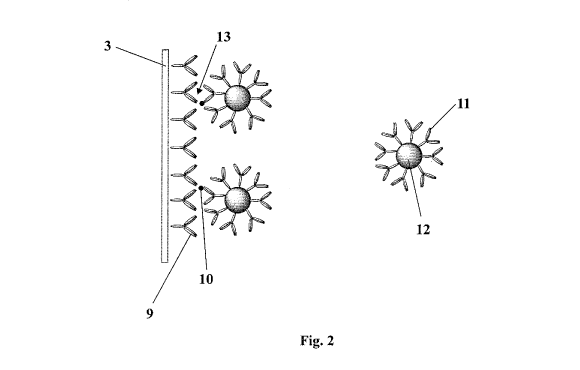
Fig. 2 shows the incorporation of the device I from Fig. 1 in an anti-complex
immunoassay of in accordance with the present invention. The transducer 3 is
shown in
a vertical arrangement, although other orientations are possible and even
advantageous
in some circumstances. The transducer 3 is coated with a first reagent shown
in Fig. 2
as a first antibody 9 (an immobilised capture antibody). The sample also
contains an
6
CA 02719036 2010-09-20
WO 2009/122206 PCT/GB2009/050310
analyte 10 and a second antibody 11 bound to a label 12 (which corresponds to
the
substance 2 in Fig. 1).
The first reagent 9 has a binding site (a paratope) which is capable of
binding the
analyte 10 or a derivative of the analyte. The analyte 10 or a derivative of
the analyte
binds to the first reagent to form a first reagent-analyte complex. A region
(epitope) is
formed in the first reagent-analyte complex by the binding of the first
reagent to the
analyte 10 or derivative thereof. The second reagent 11 has a binding site
(paratope)
which is capable of selectively binding the region thus formed on first
reagent-analyte
complex and hence when the second reagent 11 is added, it binds to the
complex. The
binding is selective because the region formed in the first reagent-analyte
complex is
not present until that first binding event occurs. In a preferred embodiment,
the sample
and the second reagent are introduced simultaneously.
The first antibody 9 has been raised against the analyte 10 and selectively
binds to the
analyte 10 when the sample is introduced. By judicious choice of the second
antibody
11, reactivity can be chosen against an epitope formed at the junction of the
first
antibody 9 and the analyte 10, i.e. second reagent 11 has a binding site which
is capable
of selectively binding the first reagent-analyte complex 13. Thus, the second
antibody
11 can only bind to the complex 13 of the first antibody 9 and the analyte 10.
No
binding of the second antibody 11 can take place in the absence of the analyte
10 and
hence the signal obtained from the label 12 attached to the second antibody 11
is
directly proportional to the analyte concentration. However, since the second
antibody
11 recognises an epitope in the complex, the assay does not require two
separate
epitopes to be present in the analyte 10, facilitating small molecule
detection.
Importantly, the method of the present invention permits detection of the
binding of the
second antibody 11 to the first reagent-analyte complex 13 in real time,
without
separation and washing steps. This is a significant advantage in the art.
Thus, in a
preferred embodiment, the assay is carried out without removing the sample
from the
transducer 3 between the steps of exposing the sample to the transducer 3 and
irradiating the sample. Moreover, no further intervention (e.g. to separate
bound and
unbound second reagent) is required between exposing the transducer to the
sample and
irradiating the sample.
7
CA 02719036 2010-09-20
WO 2009/122206 PCT/GB2009/050310
The second reagent which is not bound to the surface is free to diffuse away
from the
surface. Preferably the second reagent is allowed to become separated from the
surface
solely by diffusion.
Although the first and second reagents are exemplified in Fig. 2 by a first
and second
antibody, the present invention is not limited thereto. Thus, although the
first and
second reagents are preferably antibodies, other reagents may also be used,
such as
nucleic acids. In a preferred embodiment, the present invention provides a
method of
performing an anti-complex antibody immunoassay to detect an analyte
(sometimes
referred to as a "hapten", being a small molecule which, when attached to a
large carrier
such as a protein, can elicit an immune response) in a sample, comprising the
steps of.
providing a transducer having a pyroelectric or piezoelectric element and
electrodes
which is capable of transducing a change in energy to an electrical signal, a
first
antibody immobilised on the transducer, the first antibody having a binding
site which is
capable of binding the analyte or a derivative of the analyte, exposing the
sample to the
transducer thereby allowing the analyte or a derivative of the analyte to bind
to the first
antibody to form a first antibody-analyte complex; introducing a second
antibody, the
second antibody having a binding site which is capable of selectively binding
the first
antibody-analyte complex, wherein the second antibody has a label attached
thereto
which is capable of absorbing electromagnetic radiation to generate energy by
non-
radiative decay; irradiating the sample with electromagnetic radiation;
transducing the
energy generated into an electrical signal; and detecting the electrical
signal. The first
antibody is raised to the analyte or derivative thereof, and the second
antibody is raised
to the complex such that it contains an epitope present in the complex formed
between
the first antibody and the analyte or derivative thereof, but not present
either of the first
antibody or analyte/derivative thereof when taken alone.
The first reagent 9 is shown in Fig. 2 attached to the surface of the
transducer 3 and is
preferably adsorbed on to the transducer. The surface may also be covered by
further
coatings to stabilise the surface, e.g. Stabilcoat from SurModics Inc, Eden
Prairie, MN,
USA.
As discussed with reference to Fig. 2, the second reagent 11 has a label 12
attached
thereto. The label 12 is capable of absorbing the electromagnetic radiation
generated by
8
CA 02719036 2010-09-20
WO 2009/122206 PCT/GB2009/050310
the radiation source to generate energy by non-radiative decay. Thus, to
detect the
presence of the label 12 proximal to the transducer 3, the sample is
irradiated with a
series of pulses of electromagnetic radiation. The transducer 3 transduces the
energy
generated into an electrical signal and the electrical signal is detected by
detector 7.
The label 12 may be any material which is capable of interacting with the
electromagnetic -radiation generated by the radiation source to generate
energy by non-
radiative decay. Preferably the label is selected from, but not limited to, a
carbon
particle, a coloured-polymer particle (e.g. coloured latex), a dye molecule,
an enzyme, a
fluorescent molecule, a metal (e.g. gold) particle, a haemoglobin molecule, a
magnetic
particle, a nanoparticle having a non-conducting core material and at least
one metal
shell layer, a red blood cell, and combinations thereof.
In the case of a magnetic particle, the electromagnetic radiation is radio
frequency
radiation. All of the other labels mentioned hereinabove employ light, which
can
include IR or UV radiation. Preferably the label is a gold particle or a
carbon particle.
Carbon particles have benefits in that they absorb essentially uniformly at
all
wavelengths of interest and are much less dense than most metallic particles
minimising
their sedimentation during the assay. Gold particles are commercially
available or may
be prepared using known methods (see for example G. Frens, Nature, 241, 20-22
(1973)). For a more detailed explanation of the nanoparticle label see US
6,344,272 and
WO 2007/141581. Carbon particles are commercially available, for example, from
Degussa, Essen, Germany and methods for their conjugation with proteins and
small
molecules are known in the art, for example, by Van Doom et al. (US5641689)
Preferably, the present invention uses a particle having a particle size of 20
to 1,000 nm,
more preferably 100 to 500 nm. By particle size is meant the diameter of the
particle at
its widest point.
The label 12 is proximal to the transducer when the binding event has
occurred. That is,
the label is sufficiently close to the surface of the transducer for the
transducer to be
able to detect the energy generated by the label on irradiation of the sample.
The actual
distance between the label and the surface of the transducer will, however,
depend on a
number of variables, such as the size and nature of the label, the size and
nature of the
9
CA 02719036 2010-09-20
WO 2009/122206 PCT/GB2009/050310
first and second antibodies and the analyte, the nature of the sample medium,
and the
nature of the electromagnetic radiation and the corresponding setting of the
detector.
With regard to the nature of the electromagnetic radiation, the device of the
present
invention may include a radiation source which is adapted to generate a series
of pulses
of electromagnetic radiation and the detector is adapted to determine the time
delay
between each pulse of electromagnetic radiation from the radiation source and
the
generation of the electric signal thereby allowing a precise determination of
the position
of the label with respect to the transducer as discussed with reference to
Fig. 1.
The unknown sample is expected to contain the analyte, but of course the assay
of the
present invention may be used to determine the presence or absence of the
analyte. The
analyte is preferably a small molecule insofar as the assay is ideally suited
for such a
molecule, although the present invention is not limited thereto. The term
"small
molecule" used herein is a term of the art and is used to distinguish the
molecule from
macromolecules such as proteins and nucleic acids. A small molecule is often
referred
to in the field of immunoassays as a "hapten", being a small molecule which,
when
attached to a large carrier such as a protein can elicit an immune response
and includes
molecules such as hormones and synthetic drugs. A small molecule of this type
will
typically have a molecular weight of 2,000 or less, often 1,000 or less and
even 500 or
less. The first reagent may be adapted to bind to the analyte itself, although
the analyte
can undergo a chemical reaction or initial complexing event before binding to
the first
reagent. For example, the analyte might be protonated/deprotonated in the pH
of the
assay conditions. Thus, the analyte which is bound to the first reagent may be
analyte
itself or a derivative of the analyte; both are included within the scope of
the present
invention.
The sample which may or may not contain the analyte of interest will generally
be a
fluid sample and usually a biological sample (hence aqueous), such as a bodily
fluid,
e.g. blood, plasma, saliva, serum or urine. The sample may contain suspended
particles
and may even be whole blood. An advantage of the method of the present
invention is
that the assay may be performed on a sample which does contain suspended
particles
without unduly influencing the results of the assay. The sample will typically
be in the
order of microlitres (e.g. 1-100 L, preferably 1-10 .tL). In order to hold a
fluid
sample, the transducer is preferably located in a sample chamber and more
preferably a
CA 02719036 2010-09-20
WO 2009/122206 PCT/GB2009/050310
well. In a preferred embodiment, the transducer is integral with the chamber,
i.e. it
forms one of the walls which define the chamber. The sample may simply be
retained
by surface tension forces, for example, inside a capillary channel.
The present invention also provides a kit for performing the assay described
herein.
The kit comprises a device for detecting an analyte in a sample substantially
as
described herein with reference to Fig. 1. The device comprises a transducer
having a
pyroelectric or piezoelectric element and electrodes which is capable of
transducing a
change in energy to an electrical signal, a first reagent immobilised on the
transducer,
the first reagent having a binding site which is capable of binding the
analyte or a
derivative of the analyte, a source of electromagnetic radiation, and a
detector for
detecting the electrical signal. The kit further comprises the second reagent.
In a
preferred embodiment, the second reagent is releasably attached to one of the
interior
surfaces of the chamber prior to use. By releasably attached is meant that the
second
reagent is attached to the surface, e.g. by being dried down on to the
surface, but is
released when the sample is introduced. In a preferred embodiment, the device
consists
essentially of the above-described features. By "essentially" is meant that no
other
features are required to perform the assay.
The device may take the form of a hand-held portable reader and a disposable
device
containing the transducer. The sample is collected in an essentially closed
system,
mixed with the second reagent and placed in a reader that would perform the
irradiation
of the sample and detection of the resultant electrical signal.
The present invention further provides for the use of a transducer having a
pyroelectric
or piezoelectric element and electrodes for detecting a binding event in an
anti-complex
antibody immunoassay. The anti-complex antibody immunoassay is the assay which
involves the binding of the second antibody to the complex of the first
antibody and the
analyte or derivative of the analyte.
11
CA 02719036 2010-09-20
WO 2009/122206 PCT/GB2009/050310
Examples
Example 1
Preparation of active piezo/pyrofilm biosensors
A poled piezoelectric polyvinylidene fluoride (PVDF) bimorph film, coated in
indium
tin oxide used as the sensing device in the following examples, was dip-coated
in
polystyrene solution (1% in toluene) in a low humidity environment to give a
polystyrene layer on top of the indium tin oxide. This was then coated in
polystreptavidin solution (200 pg/mL in PBS - 10 mmol/L phosphate buffer
containing
2.7 mmol/L KCI, 137 mmol/L NaCl and 0.05% Tween) by incubation at room
temperature overnight. Polystreptavidin was prepared as described by Tischer
et al (US
5,061,640).
To prepare a "capture" surface, the polystreptavidin surface was incubated
with
biotinylated anti-testosterone (MI), giving an antibody coated surface (Cl).
10 uglmL
of biotinylated anti-testosterone (HyTest Ltd, Turku, Finland, Cat # 2T2-
biotin, or
Accurate Chemical Co, Westbury, New York, USA, Cat # BHS 113) in PBS was
incubated at room temperature overnight and then washed with excess PBS and
coated
with Stabilcoat (SurModics Inc, Eden Prairie, MN, USA) before drying at 40 C.
Example 2
Preparation of secondary antibodies
Secondary monoclonal antibodies (M2), reactive against the capture antibody
(Ml)-
testosterone complex were raised essentially as described in C.H. Self et al
Clin. Chem.
1996, 42, 1527-1531 and biotinylated by methods know to those skilled in the
art. For
example, a 5 mg/ml antibody solution in PBS (NaCl 150 mmol/L, phosphate 20
mmol/L, pH 7.5) is prepared by dissolving lyophilised antibody, or by
dilution. If this
solution contains other proteins or Tris or other interfering agents, purify
by dialysis or
gel filtration. Then prepare an NHS-biotin solution at 20 mmol/L in anhydrous
DMSO
and add 15 .iL of the solution of NHS-biotin to the antibody (I mL). Incubate
for 1
12
CA 02719036 2010-09-20
WO 2009/122206 PCT/GB2009/050310
hour at room temperature and then dialyse the antibody against PBS containing
sodium
azide (0.01%). The biotinylated antibody can be diluted to 1 mg/mL with 0.1%
sodium
azide and 20% of glycerol for storage at -20 C or +4 C. The level of
biotinylation
should be in the range of 1-3 biotins per IgG. This can be estimated by
quantitation of
biotins or for high biotinylation rates, by a differential quantitation of
amines.
Example 3
Preparation of the reporter conjugates
Carbon-labelled reporter conjugates were prepared essentially as described by
Van
Doom et al. (US 5,641,689). To prepare antibody coated reporter conjugates
(RI), 1
mL of Special Black-4 RCC nominally 150 nm carbon particles (Degussa, Essen,
Germany) in 5 mmol/L phosphate buffer, pH 6.2 was incubated with 200 g/mL
polystreptavidin solution overnight at room temperature with shaking,
resulting in a
streptavidin-coated surface (Al). The resultant carbon conjugate was washed
(by
centrifugation, pelleting and resuspension). 10ug/mL of biotinylated secondary
monoclonal antibodies (M2), reactive against the capture antibody (Ml)-
testosterone
complex, in PBS was then incubated overnight with 1 mL of this streptavidin-
coated
carbon particle suspension with shaking. The resultant carbon conjugate (C2)
was
washed (by centrifugation, pelleting and resuspension) 3 times with 0.05 mol/L
borate
buffer at pH 8.5 and stored in this buffer in the dark at 4 C.
Example 4
Assay w. Antibody-coated piezo/pyrofilm sensor
As shown in Fig. 3, a sensor 1 was fabricated to perform the assay: The sensor
1 is
fabricated from a piece of antibody-coated piezofilm 3 (C1, described
hereinabove) and
a piece of transparent polycarbonate lidding film 14. The films are spaced at
a distance
of approximately 500 microns using a spacer 15 composed of a piece of pressure
sensitive adhesive-coated polyester film die-cut to form two unequally sized
chambers
16,17; one chamber 16 of approximate dimensions 30 x 10 x 0.5 mm for the assay
reaction and a second smaller chamber 17 of dimensions 10 x 10 x 0.5 mm for a
control
13
CA 02719036 2010-09-20
WO 2009/122206 PCT/GB2009/050310
reaction. Provision is made to allow for electrical connections to the top and
bottom
surfaces of the piezofilm in order to detect the charge generated.
Assays are carried out by filling the larger chamber 16 (through a fill hole
18) with a
mixture of 0.1 mol/L Tris buffer, containing 0.150 mol/L MgC12 and 0.075%
Tween 20
solution, containing 150 nm colloidal carbon particles (at a final
concentration of
0.0025% solids) coated with biotinylated antibody (C2, as described
hereinabove),
reactive against the capture antibody (Ml)-testosterone complex, and
testosterone
standards in PBS to give a final concentration range of 0.1-100 nmol/L. The
control
chamber 17 is simultaneously filled an identical reaction mix to that in the
assay
chamber with the testosterone standard replaced with PBS. The entry and exit
holes are
sealed and the chamber assembly is connected to a test instrument such that
the
piezofilm 3 is oriented vertically on the side face of the chamber. The
piezofilm is then
illuminated with chopped LED light sequentially with four LEDs (of wavelength
625
nm), of which three illuminate different areas of the surface of the assay
chamber and
one illuminates the piezofilm surface of the control chamber. For each LED
pulse, a
voltage is measured across the piezofilm using a lock-in amplifier and
analogue to
digital (ADC) converter. The ADC signal is plotted over time and the
relationship of
ADC counts/min against testosterone concentration is shown in Fig. 4.
14