Note: Descriptions are shown in the official language in which they were submitted.
CA 02719123 2010-10-27
AUTO HAMMER
BACKGROUND
There are various auto hammers. In accordance with the type of the power
source utilized,
auto hammers may be generally divided into two types, i.e., pneumatic auto
hammers and
electric auto hammers. In accordance with the way of working, auto hammers may
also be
divided into single-strike-action type and continuous-strike-action type.
The auto hammers of single-strike-action type are usually subject to the
objects and the
environments, e.g., they are usually used to strike nails of smaller
dimensions into softer objects
such as wood boards. When nails of large dimensions are considered, or when
the material of the
objects to be fixed is hard, nails can not be stricken in by a single-strike-
action. In this situation,
the nails tend to be bent or seized, or may even damage the tool. In this
case, auto hammers of
continuous-strike-action type are desired.
Additionally, the users pay more and more attention to the circumstances where
the tools
may be used.
SUMMARY
The following describes an improved auto hammer which can be used between two
surfaces perpendicular to each other and closer to the intersecting line of
the two surfaces. To this
end, the auto hammer comprises a housing having an upper portion, a motor
contained in the
housing, and a switch arranged on the housing for controlling the motor. When
the auto
1
CA 02719123 2010-10-27
hammer is used between two surfaces perpendicular to each other with its
opposite sides of the
upper portion of the housing abutting against the two surfaces respectively,
the distance from the
central axis of the striking rod to the intersecting line of the two surfaces
is between 10mm and
40mm, preferably 28mm. This distance is arranged very small for facilitating
the auto hammer
to be used closer to the intersecting line of the two surfaces.
The auto hammer comprising a housing having a grip portion defining a central
axis, and
a head assembly including a striking device which has a striking rod defining
a central axis.
The striking device is pivotable relative to the grip portion, and the angle
between the central
axis of the grip and the central axis of the striking rod is between 60 and
180 . The auto
hammer comprises a pivotable striking device, and is thereby suitable for
different working
circumstances.
The auto hammer may also comprise a head assembly which includes a
transmission
mechanism for converting the rotating motions of the motor into the linear
reciprocating motions
of the striking rod.
The head assembly of the auto hammer may still comprise a striking rod. The
distance
between the central axis of the striking rod and the top portion of the head
assembly is between
5mm and 26mm, preferably 10.7mm. This distance is arranged very small for
facilitating the
auto hammer to be used closer to a base wall.
The material arranged for the head assembly of the auto hammer is different
from that of
the housing. Preferably, the hardness of the material arranged for the head
assembly such as
2
CA 02719123 2010-10-27
TPE is lower than that of the material of the housing such as ABS. During
operation, the
material arranged for the head assembly makes the head assembly feel more
comfortable when
held by hands.
The material arranged for the grip of the auto hammer is different from that
of the
housing. Preferably, the hardness of the material arranged for the grip such
as TPE is lower
than that of the material of the housing such as ABS. During operation, the
material arranged
for the head assembly make the head assembly feel more comfortable when held
by hands.
The distance between the end surface of the striking end of the striking rod
and the center
of the impact wheel of the auto hammer is between 40mm and 100mm, preferably
70mm. This
distance is arranged very small, in favor of the auto hammer being used in
narrower spaces.
The distance between the opposite sides of the upper portion of the housing of
the auto
hammer is between 50mm to 80mm, preferably 66mm. This distance is arranged
very small, in
favor of the auto hammer being used in narrower spaces.
In this present invention, the distance arranged between the central axis of
the striking
rod of the auto hammer and the intersecting line of two surfaces perpendicular
to each other is
very small, in favor of the hammer being used more closer to the intersecting
line.
BRIEF DESCRIPTION OF THE DRAWINGS
The detailed descriptions for this invention will be illustrated by the
preferred
embodiments with reference to the following accompanying drawings, wherein:
Fig. 1 is a profile view of an auto hammer in accordance with the ergonomics
according to
3
CA 02719123 2010-10-27
the first embodiment of the present invention, with the auto hammer being
positioned
transversely;
Fig. 2 is a profile view of the auto hammer of the first embodiment, with the
auto
hammer being positioned vertically;
Fig. 3 is a cross-sectional view of a head assembly of the auto hammer in Fig.
2 along the
A-A axis;
Fig. 4 is an illustrative view showing the auto hammer of the first embodiment
adapted
for use in a narrow space;
Fig. 5 is an illustrative view showing the auto hammer of the first embodiment
adapted
for use near a base wall;
Fig. 6a is a schematic view of two surfaces that are perpendicular with each
other;
Fig. 6b is a plan view showing the auto hammer adapted for use in the corner
of the two
surfaces being right angled with each other in Fig. 6a;
Fig. 7 is an illustrative view showing the auto hammer of the first embodiment
adapted
for being placed on the working board;
Fig. 8 is an illustrative view showing the auto hammer of the first embodiment
adapted
for use in another narrow space;
Fig. 9 is an illustrative view showing the auto hammer of the first embodiment
adapted to
be operated by a single hand;
Fig. 10 is an illustrative view showing the auto hammer of the first
embodiment adapted
4
CA 02719123 2010-10-27
to be operated by hands;
Fig. 11 is an illustrative view showing the shapes of the hand and the soft
covering of the
hammer;
Fig. 12 is an illustrative view showing the grasp position for an auto hammer
of a second
embodiment;
Fig. 13 is an illustrative view showing another grasp position for the auto
hammer of the
second embodiment;
Fig. 14 is a schematic view of an auto hammer of a third embodiment, wherein
the
receiving cavity thereof is lockable;
Fig. 15 is a schematic view of the auto hammer in Fig. 14, with the receiving
cavity
thereof being shown in a locked state;
Fig. 16 is an exploded view of an auto hammer of a fourth embodiment, wherein
the
striking device thereof is rotatable;
Fig. 17 is a cross-sectional view of the locking mechanism of the fourth
embodiment;
Figs. 18-20 are schematic views of the auto hammer of the fourth embodiment,
with the
angle a between the central axis of the striking rod and the central axis of
the grip being shown
in 60 , 90 and 180 respectively;
Figs. 21-23 are schematic views of an auto hammer of a fifth embodiment, with
the angle
a between the central axis of the striking rod and the central axis of the
grip being shown in 60 ,
110 and 180 respectively;
5
CA 02719123 2010-10-27
Fig. 24 is a sectional view taken along axis B-B in Fig. 23;
Fig. 25 is a perspective view of the auto hammer of the first embodiment;
Fig. 26 is a sectional view of the auto hammer as shown in Fig. 25 taken along
the
combination surface of the two halves of housing, wherein the battery pack of
the nailer device is
removed for clarity;
Fig. 27 is a sectional view of the auto hammer as shown in Fig. 25 taken along
the
direction perpendicular to the combination surface of the two halves of
housing, wherein the
battery pack of the nailer device is removed for clarity;
Fig. 28 is a partial exploded view of the transmission device of the auto
hammer in Fig.
25;
Fig. 29 is a sectional view of the striking device of the auto hammer in Fig.
25, with the
striking device being shown in an initial position; and
Fig. 30 is a sectional view of the striking device of the auto hammer in Fig.
25, with the
striking device being shown in a stricken position.
DETAILED DESCRIPTION
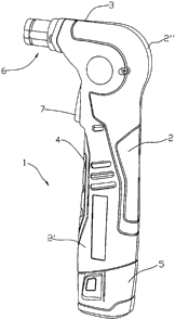
As shown in Figs. 25 and 26, the auto hammer 1 according to this embodiment
comprises
a striking device 6 and a housing 2 containing a motor M therein. The housing
2 is formed by
joining two halves 2' and 2" in juxtaposition. A substantially vertical grip 4
is formed by a
main portion of the housing 2. An upper portion of the housing 2 includes a
head assembly 3
comprising a transmission mechanism and a striking device 6.
6
CA 02719123 2010-10-27
ti
In this embodiment, the auto hammer 1 includes a battery pack 5 for supplying
electricity
to the motor M. However, the auto hammer according to the present invention
need not be
restricted to the use of a DC power supply and may be equally powered by a
source of AC power.
A switch 7 is arranged on the housing 2 for controlling the motor M. The
striking device 6
includes a striking rod 61 mounted therein by a spring. The striking rod 61 is
disposed
substantially horizontal and is moved linearly in a reciprocating manner
within the striking device
6. During operation, the striking end 611 of the striking rod 61 is moved to
act with its end
surface on the components such as fastening pieces like nails and tenons or
objects like bricks, etc.
The striking device 6 also contains a receiving cavity 63 therein which is
designed to be a
retractable structure, which may contact with the surface of the objects to be
processed.
Additionally, the receiving cavity 63 has an inner diameter larger than that
of normal fastening
pieces. As a result, fastening pieces of all kinds of dimension may all be
placed into the
receiving cavity 63.
As shown in Figs. 27-30, a rotation-linear movement transmission mechanism is
arranged
in the housing 2 for converting rotating motions of the motor M into impact
motions of the
striking rod 61. The motor M is mounted vertically in the housing 2 with an
upward motor
shaft X' connected with a multi-stage gear transmission mechanism including
bevel gear. In this
way, the rotation power of the motor 2 is transmitted to the rotating shaft 35
which is mounted in
the upper portion of the housing 2 by the bearings on its both ends. A pair of
inclined slots 36
is formed on the rotating shaft 35, each of which is "V" shaped and opens
backwardly. An
7
CA 02719123 2010-10-27
impact wheel 31 is mounted on the rotating shaft 35. The impact wheel 31 is
substantially a
hollowed cylinder comprising a pair of arcuate guiding slots 37 which are
formed on its inner
wall and opposite to the two inclined slots 36 respectively. Each of the
guiding slots 37 is
opened with its arcuate portion in a direction opposite to that of the
corresponding "V" shaped
inclined slot 36. The inclined slots 36 and the guiding slots 37 both have a
semicircle bottom.
A pair of steel balls 38 is arranged movably in two chambers formed by the
corresponding
inclined slot 36 and guiding slot 37. When the inclined slots 9 are moved with
the rotating shaft
35 relative to the guiding slots 37, the chambers formed thereby are moved
with a result that the
steel balls 38 can be moved along with the chambers. The impact wheel 31 can
thus be driven to
rotate through the steel balls 38 within the inclined slots 36 when the
rotating shaft 35 is rotated.
A pair of projections 32, which are extended along the diameter direction of
the rotating wheel
38, is provided on the periphery of the rotating wheel. When the switch 7 is
triggered, the motor
M is actuated and drives the rotating shaft 35 to rotate through multi-stage
gear transmission
mechanism. As a result, the rotating shaft 35 then drives the impact wheel 31
to rotate therewith
via the steel balls 38.
As shown in Figs. 29 and 30, the striking rod 61 of the striking device 6 of
the auto
hammer 1 is inserted into a shaft sleeve portion 39 which is formed integrally
with a gear
housing. A restoring spring 62 is mounted by encircling the striking rod 61 in
such a manner
that one end of the spring 62 bears against a shoulder 613 of the striking rod
61, and the other
end of the spring 62 bears against the end surface of the shaft sleeve portion
39. The restoring
8
CA 02719123 2010-10-27
spring 62 exerts a spring force toward the outside of the housing onto the
striking rod 61, along
the longitudinal direction of the striking rod 61. When there is no external
force acting on the
striking rod 61, the stricken end 612 of the striking rod 61 is located at an
initial position where it
is not contactable with the projections 32 of the impact wheel 31 due to the
spring force of the
spring 62, as shown in Fig. 29. In this case, the spring 62 exhibits a first
elastic state, and the
stricken end 612 of the striking rod 61 is located out of the circular motion
track of the
projections 32. When there is an external force acting on the striking rod 61,
e.g., when a
fastening piece needs to be striken into a solid object, the striking rod 61
receives a larger
resistance which overcomes the spring force of the spring 62 and urges the
striking rod 61 to
move toward the impact wheel 31. When the striking rod 61 reaches the position
shown in Fig.
30, the spring 62 exhibits a second elastic state. In this state, the striking
rod 61 is located at a
stricken position where it is contactable with the projections 32 of the
impact wheel and its
stricken end 612 is in the circular motion track of the projections 32. As a
result, there is one
position in the circular motion track of the projections 32 where the
projection 32 can contact
with the stricken end 612 of the striking rod 61.
The restoring spring 62 mentioned above could be formed as a compression
spring or a
coil spring. However, it is easily conceivable for those skilled in the art
that other elastic
members or biasing members producing attraction forces or exclusion forces,
such as magnetic
members, may be used to replace the spring 62.
As shown in Fig. 28, an energy storing spring 40 is mounted between the impact
wheel
9
CA 02719123 2010-10-27
31 and the rotating shaft 35 in manner that one end of the energy storing
spring 40 abuts to the
shoulder 351 of the rotating shaft 35 and the other end of the energy storing
spring 40 abuts to a
side surface of the impact wheel 31. Under an axial biasing force of the
energy storing spring
40 acting upon the impact wheel 31 along the axial direction of the rotating
shaft 35, the impact
wheel 31 is located at a first axial position relative to the rotating shaft
35. In the first axial
position, the impact wheel 31 rotates circumferentially by means of the
rotating shaft 35 and the
steel balls 38. If the striking rod 61 is now located at the stricken position
as shown in Fig. 30,
when the impact wheel 31 is rotated to a position where the projections 32
contact the striking
rod 61, and the striking rod 61 encounters a larger resistance that is
difficult to be overcome
provisionally, the impact wheel 31 is temporarily stopped from rotating by the
striking rod 61, so
that the impact wheel 31, under the cooperation of the steel balls 38, the
guiding slots 37 and the
inclined slots 36, overcomes the axial force of the spring 40, compresses the
energy storing
spring 40 and moves from the first axial position to a second axial position
relative to the
rotating shaft 35. At this second axial position, the projections 32 of the
impact wheel 31 depart
from the striking rod 61 and the braking is released. In this case, the energy
storing spring 40
starts to release the elastic potential energy thereof. By the rebound force
of the energy storing
spring 40, the impact wheel 31 is pressed back to its first axial position
quickly, and is moved at
a higher speed than that of the rotating shaft 35 under the cooperation of the
inclined slots 36, the
guiding slots 37 and the steel balls 38. As a result, the stricken end 612 of
the striking rod 61 is
impacted by the projections 32 on the impact wheel 31 to move at a high speed
in a linear
CA 02719123 2010-10-27
direction away from the projections 32 and the striking rod 61 strikes the
head of the nail quickly.
After the first striking action is finished, the striking rod 61 is pressed
back to its initial position
as shown in Fig. 29 under the rebound force of the restoring spring 42. When
the impact wheel
31 is continuously driven to rotate to be stopped by the striking rod 61, it
enters into succeeding
cycles, which will be achieved in the same manner.
Fig. 1-11 show a profile view of the auto hammer of the first embodiment
according to
this invention, which is in accordance with the ergonomics. An auto hammer of
low effort,
easy operation and comfortable grip is provided to satisfy the ergonomics. As
shown in Fig. 1,
the head assembly 3 is arranged on the left end of the housing 2 and the
battery pack 5 is
arranged on the right end of the housing 2. The weight constituting the auto
hammer 1
includes the head assembly 3, the motor (as shown in Fig. 26) and the battery
pack 5. The
gravity center of the head assembly 3 lies at point A in Fig. 1, the gravity
center of the motor lies
at the grip 4, and the gravity center of the battery pack lies at point B, so
that the gravity center
of the auto hammer as a whole lies at point C. The head assembly 3 and the
battery pack 5 are
respectively disposed at the two ends of the housing 2, so that their gravity
centers A and B are
located at the opposite ends of the grip 4, respectively. As a result, the
gravity center C of the
tool 1 is located at the hand-holding position as shown in Fig. 9 when the
tool 1 is operated by
hand. With such configuration, the user feels more comfortable during
operation. It could be
understood that the whole gravity center may also be located at the hand-
holding position of the
tool by arranging the head assembly and the motor respectively at the two ends
of the housing
11
CA 02719123 2010-10-27
when other ways of power supply, such as alternating current, are adopted.
Figs. 2-4 are dimensional views of the head assembly of the first embodiment.
In this
embodiment, fastening pieces, such as nails, screws, pins, staples and the
like can be received in
the receiving cavity 63. The housing 2 includes an upper portion 2a. In favor
of the tool 1
being used in a narrow space 8 which is restricted in the horizontal direction
as shown in Fig. 8,
the distance D from the end surface of the striking end 611 of the striking
rod 61 to the center of
the impact wheel 31, which is usually between 40mm-I00mm, is preferably 70mm.
For use of
the tool 1 in a narrow space 9 that is restricted in the vertical direction as
shown in Fig. 4, the
distance F between the opposite sides of the upper portion of the housing,
which is usually
between 50mm-80mm, is preferably arranged at 66mm. It will be understood that,
in favor of
the tool 1 being used in a narrow space (not shown) that is restricted both in
the horizontal
direction as shown in Fig. 8 and in the vertical direction as shown in Fig. 4,
the distance D and F,
which are usually between 40mm-I00mm and 50mm-80mm respectively, are
preferably
arranged at 70mm and 66mm respectively at the same time.
As shown in Fig. 2, a lighting source 10 constructed as a LED is arranged at
the left
portion of the housing 2 under the receiving cavity 63. When the switch 7 is
pressed, the
lighting source 10 will work with the tool 1 to light the receiving cavity 63
and the surface of the
objects to be processed. With such configuration, the fastening pieces can be
nailed into the
working piece to be processed reliably and accurately even in a low light
condition. In spite of
the influence of the vibrations during operation, the lighting source 10 will
still achieve a good
12
CA 02719123 2010-10-27
lighting effect if the lighting source is a LED, in particular a LED of high
energy. However,
the lighting source may also be replaced by other lighting device such as
incandescence lamp.
In good light conditions, an additional separate switch (not shown) may also
be arranged to
control the lighting source 10, so as to increase the lifetime for the battery
to be used.
In this embodiment, in order to facilitate the tool 1 to be used near the base
wall 11
shown in Fig. 5, the distance E between the central axis Y of the striking rod
61 and the top
portion 3a of the head assembly, which is usually between 5mm-26mm, is
preferably arranged at
10.7mm. By such a configuration, the striking rod 61 is closer to the base
wall I1 so that the
fastening pieces are nailed near the base wall 11. In favor of the tool 1
being used in the area
12 between two surfaces that are perpendicular to each other as shown in Figs.
6a, 6b, the
distance G from the central axis of the striking rod to the intersecting line
12a of the two surfaces
P1, P2, which is usually arranged between IOmm-40mm, is preferably 28mm when
the opposite
sides of the upper portion of the housing of the tool 1 abut against the two
surfaces. As a result,
the tool 1 may be used closer to the intersecting line of these two surfaces.
Fig. 7 shows a schematic view of the housing, with a soft covering arranged on
the
opposite sides of the upper portion thereof. In this embodiment, in favor of
the tool 1 being
positioned on a work board 13, the housing 2 is preferably made from ABS
material, with soft
covering 14 which is made from PVC or TPE material, being arranged on the
opposite sides of
the upper portion of the housing. Usually, the material on opposite sides of
the upper portion
of the housing is different from that of the remaining portion of the housing
2. When the tool
13
CA 02719123 2010-10-27
is positioned transversely on the working board 13, the hardness of the soft
covering 14 is lower
than that of the material of the housing, so as to protect the tool 1 and the
working board 13.
When the tool 1 falls off from hands, the soft covering 14 may also protect
the tool 1.
Figs. 8-11 are schematic views of the head assembly with soft covering
arranged thereon.
Preferably, in this embodiment, the tool 1 is arranged with soft covering 15
made from TPE
material on its head portion for convenient operation. The soft covering 15 is
molded together
with one half-housing, forming a PE line 16. Likewise, there is also a
symmetrical PE line 16
(not shown) on the other half-housing symmetrical to said one half-housing.
Usually, the
material of the head portion of the tool 1 is different from that of remaining
portion of the
housing. As shown in Figs. 9-11, the dashed lines show the portions with PE on
the housing.
When the pressure applied by a single hand during operation isn't sufficient,
a larger pressure
may be provided by one hand gripping the soft covering of the grip and the
other hand pressing
the head portion. Therefore, the soft covering arranged in the head portion
can enhance the
comfortableness during operation. The hardness of the soft covering is less
than that of the
material of the housing and conforms to ergonomics in its shape, such that the
fingers and the
palm may just contact the soft covering 15 during operation.
Figs. 12-13 are illustrative views showing the grip manners for the auto
hammer
according to a second embodiment, wherein similar components with the same
effect and
function in different embodiments are indicated by like numerals, which is
similar hereinafter.
As shown in Fig. 2, the switch 7 is small-sized, and is arranged in the grip
portion 4 close to the
14
CA 02719123 2010-10-27
head assembly 3. However, when the working conditions is restricted, such as
when the head
assembly 3 and the switch 7 enter into an narrow space where the hands can't
reach to trigger the
switch, it is desirable for a switch 71 of long dimension as shown in Fig. 12,
so that the proximal
end 71 a of the long switch 71 can be operated by hand. Furthermore, with such
a switch of
long dimension, the distal end 71b of the long switch 71 can also be operated
by hand for other
working conditions, such as the space under machines where the hands can't
reach. By this
configuration, there are at least two grip positions for hands to meet
different working conditions
and improve the convenience of the tool.
Figs. 14-15 are schematic views of an auto hammer of a third embodiment,
wherein the
receiving cavity thereof is lockable. Auto hammer 1 can be used to strike all
kinds of objects.
In some circumstances for frequent strike, a lot of physical labor will be
consumed during
operation of a manual hammer. On the contrary, using the auto hammer will
bring the user a
lot of convenience and save labor. The concrete configuration of the auto
hammer will be
described hereinafter: A locking pin 18 is arranged on the housing 2 or the
support 17. A
locking hole 19 is provided on the member having the receiving cavity 63. When
the member
having the receiving cavity 63 is pushed into the shelf 17 and the locking
hole 19 is just below
the locking pin 18, the member having the receiving cavity 63 will be
retracted into the housing
and be locked by pressing the locking pin 18 downwardly, with the striking rod
61 being
revealed to increase the visibility of the striking rod 61. In this case, the
striking end 611 of the
striking rod 61 may function as a striking portion of the auto hammer. During
operation, the
CA 02719123 2010-10-27
objects to be processed, such as tenons and bricks, may be impacted by the
striking rod 61 in a
linear reciprocating manner, so that the function of the tool can be expanded,
without limiting
the tool to knocking fastening pieces into the objects to be processed. It
will be understood for
those skilled in the art that member having the receiving cavity 63 is made
from transparent
material such as transparent plastic to increase the visibility of the
striking rod 61. The user
may use the tool as an auto hammer to strike the objects to be processed when
he/she could see
the specific position of the striking rod 61.
As shown in Figs. 16-20, the striking device of the auto hammer can rotate.
The
striking device 6 can pivot about the central axis Z of the impact wheel 31
relative to the grip 4.
The left and right rotating half-covers 20, 21 are preferably configured with
symmetrical
semi-circle openings 22, which may also be usually arranged as integral
configuration. The
left and right rotating half-covers 20, 21 are provided with rings 23, 24. The
gear housing 25
are arranged with protruding cylinders 26, 27 on both ends. During assembly,
the left and right
rotating half-covers 20, 21 are combined with each other, such that the two
semi-circle openings
22 form an entire circle opening, into which the striking rod 61 is inserted.
The small screws
28 on opposite sides of the rotating covers 20, 21 are fitted into the U-
shaped slots 613, so that
the striking rod 61 is axially stopped. The member having the receiving cavity
63 passes
through the shelf 17 which is fixed on the left and right half-covers 30, 33
by means of screws 29.
Meanwhile, the two rings 23, 24 on the left and right rotating half-covers 20,
21 are mounted on
the two protruding cylinders 26, 27 of the gear housing 25, respectively. The
rings 23, 24 and
16
CA 02719123 2010-10-27
the cylinders 26, 27 are all arranged coaxially with the axis Z of the impact
wheel 31, so that the
left and right rotating half-covers 20, 21 may pivot about the axis Z. The
housing 30 is
composed of two symmetrical halves 30a, 30b, which are respectively fixed on
the left and right
rotating half-covers 20, 21 by screws (not shown). Finally, the left and right
grips are
combined and mounted to encircle the protruding cylinders 26, 27 on the gear
housing 25. A
light source 10 is arranged on the housing 30, which can rotate together with
the striking device
6, so that it may light the receiving cavity 63 and the surface of the objects
to be processed no
matter the striking device rotates to what direction.
With reference to Figs. 16-20, the auto hammer 1 further includes a locking
mechanism
34 for restricting the pivotal movement of the striking device 6 relative to
the grip 4. The
locking mechanism 34 includes a button 34a thereon. At least one round hole
24a is provided
on the ring 24 of the right rotating half-cover 21, within which a locking
spin 34b and a spring
are fitted. The grip 4 includes at least two round holes 4a. The striking
device 6 is locked
when the other end of the locking spin 34b enters into the round hole 4a. On
the other hand, the
striking device 6 can rotate when the button 34a is pressed and the protrusion
34c on the button
34a ejects the locking spin 34b out of the round hole 4a. The axis Y of the
striking rod 61 or its
parallel line Y' and the axis X of the grip 4 form an angle a, which may vary
between 60 and
180 when the striking device 6 pivots about the central axis Z of the impact
wheel 31. When
the striking device 6 pivots to the position shown in Fig. 18 where the angle
a is 60 and the
button 34a is released, the locking spin 34b is locked within the
corresponding round hole 4a on
17
CA 02719123 2010-10-27
the grip 4. When the button 34a is pressed, the locking spin 34b is ejected
out of the round
hole 4a, so that the striking device 6 can rotate freely to the positions as
shown in Figs. 19 and 20,
where the angle a is 90 and 180 , respectively. It could be understood that
the grip 4 may be
arranged with more round holes 4a thereon, so that the striking device 6 may
rotate freely and be
locked in any position where the angle a is from 60 to 180 .
Figs. 21-24 show another embodiment of the striking device 6 of the rotatable
auto
hammer 1. The angles a between the central axis Y of the striking rod 61 or
its parallel line Y'
and the central axis X of the grip are 60 , 110 and 180 respectively.
Similarly, a locking
mechanism 34 is provided in the auto hammer 1 for locking the striking device
6 and preventing
the same from pivotally moving relative to the grip 4. At least one round hole
24a is provided
on the ring 24 of the right rotating cover 21, within which a locking spin 34b
is fitted. When
the button 34a is pushed, the corresponding protrusion 34c ejects the locking
spin 34b out of the
round hole 4a of the grip 4 so that the striking device 6 can rotate into
other positions. When
the locking spin 34b enters into another round hole 4a of the grip 4, the
striking device 6 is
locked. With the striking rod 61 pivoting about the central axis Z of the
impact wheel, the
striking rod 61 may be fixed at different rotating angles. As a result, the
striking device 6 can be
used in various narrow spaces.
The auto hammers according to the present invention are not limited to the
contents and
configurations described above in the embodiments and shown in the
accompanying drawings.
Based on the present invention, those skilled in the art will envisage other
obvious variations,
18
CA 02719123 2010-10-27
replacement and modifications to the configurations and positions of the
elements contained,
which are also contained in the protection range of this invention.
19