Note: Descriptions are shown in the official language in which they were submitted.
CA 02719689 2016-02-19
METAL SHEATHED CABLE ASSEMBLY
Background of the Invention
Field of the Invention
[0002] The present invention is directed toward a type AC Armored Cable.
More
particularly, the present invention relates to a type AC THH armored cable
assembly which
includes electrical conductors each having a conventional layer of insulation,
a jacketing
layer and an extruded protective layer.
Discussion of Related Art
[0003] Armored cable ("AC") and Metal-Clad ("MC") cable provide
electrical
wiring in various types of construction applications. The type, use and
composition of these
cables must satisfy certain standards as set forth, for example, in the
National Electric Codes
(NEC ). These cables house electrical conductors within a metal armor. The
metal armor
may be flexible enabling the cable to bend while protecting the conductors
against external
damage during and after installation. The armor which houses the electrical
conductors may
be made from steel or aluminum. Typically, the metal armor sheath is formed
from strip
steel, for example, which is helically wrapped to form a series of interlocked
"S" shaped
sections along a longitudinal length of the cable.
[0004] Generally, AC and MC cable have different internal constructions
and
performance characteristics and are governed by different standards. For
example, MC cable
is manufactured according to UL standard 1569 and includes a conductor
assembly with no
limit on the number of electrical conductors having a particular AWG (American
Wire
Gauge). The conductor assembly may contain a grounding conductor. The
electrical
conductors and the ground conductor are cabled together in a left or right
hand lay, but must
end in a left hand lay.
1
CA 02719689 2010-09-24
WO 2009/126613 PCT/US2009/039753
The conductors are encased collectively in an overall covering. In particular,
MC cable includes
either a covering over all of the electrically insulated conductors and the
grounding conductor
after cabling or a covering over just the electrical insulated conductors
combined after cabling
while the grounding conductor is positioned externally separate from this
overall covering. The
assembly is then fed into an armoring machine where metal tape is helically
applied around the
assembly to form a metal sheath. The metallic sheath of MC cable may be used
as an equipment
grounding conductor if the ohmic resistance satisfies the requirements of UL
1569. A
grounding/bonding conductor may be included which, in combination with the
metallic sheath,
satisfies the UL ohmic resistance requirement. In this case, the metallic
sheath and the
grounding/bonding conductor would compose what is referred to as a metallic
sheath assembly.
[0005] In contrast, AC cable is manufactured to UL Standard 4 in
accordance with
Section 320 of the National Electrical Code NEC and can only contain up to
four (4) insulated
conductors (copper, aluminum, etc.) which are cabled together in a left hand
lay as per Section
5.5 of UL Standard 4. Each electrical conductor is covered with a
thermoplastic insulation and a
jacket layer which are individually wrapped in a fibrous material. Similar to
MC cable, the
electrical conductors are disposed within a metal armor or sheath. If a
grounding conductor is
employed in AC cables, the grounding conductor is either (i) separately
covered or wrapped
with the fibrous material before being cabled for thermoplastic insulated
conductors; or (ii)
enclosed in the fibrous material together with the insulated conductors for
thermoset insulated
conductors. In either configuration, the bare grounding conductor is prevented
from contacting
the metal armor by the fibrous material. Additionally in AC type cable, a
bonding strip or wire is
laid lengthwise longitudinally (not cabled) along the conductors and is in
intimate contact with
the metal armor or sheath providing a low-impedance fault return path to
safely conduct fault
current.
[0006] The bonding strip for AC cable is composed of a minimum 16 AWG
aluminum
strip or wire. The bonding strip is unique to AC cable and allows the outer
metal armor or sheath
in conjunction with the bonding strip to provide a low impedance equipment
grounding path.
NEC Section 320-104 provides that each electrically insulated conductor in an
AC cable is
covered with an overall moisture-resistant and fire-retardant fibrous material
and if a grounding
conductor is used, the fibrous material is disposed between the ground wire
and the metal
2
CA 02719689 2016-02-19
i
armored sheath. This provides that the ground conductor is separate from the
bonding strip
and allows the bonding strip to be in electrical contact with the interior
surface of the metal
sheath to provide the low impedance equipment grounding path. However, the
fibrous
material used to wrap each circuit conductor and ground conductor requires
additional time
and manpower during use and installation. In particular, an installer must
first unwrap the
fibrous material to expose the insulation/jacket before cutting the conductors
required to
complete a desired connection. In addition, the fibrous material may be
subject to
decomposition which may compromise the mechanical protection of the cable.
Although the
fibrous material may provide some moisture resistance and may be flame
retardant, it may
not provide a sufficient level of these properties for a particular
application and/or location.
Moreover, if moisture does penetrate into the fibrous material, the moisture
will not wick
away thereby potentially compromising the cable. Thus, there is a need for an
improved AC
cable that overcomes the drawbacks of the prior art.
Summary of the Invention
[0006a] Certain exemplary embodiments can provide an AC cable
comprising:
a plurality of conductor assemblies, each of said conductor assemblies having
an electrical
conductor, a layer of polyvinylchloride insulation extending around and along
the length of
each of said electrical conductors, and a polymeric protective layer disposed
around said
insulation layer along the length of each of said electrical conductors, said
protective layer
made from a material that is different from said layer of insulation; a nylon
jacket layer
disposed between said polyvinylchloride insulation layer and said protective
layer for each
of said plurality of conductor assemblies; a metal sheath disposed over said
plurality of
conductor assemblies; and a bonding strip disposed within said metal sheath
and in intimate
contact with an interior surface of said metal sheath.
3
CA 02719689 2016-02-19
_
I
[0007] Other exemplary embodiments are directed to an AC cable. In
an exemplary
embodiment, the AC cable includes a plurality of conductor assemblies, a
bonding strip and
a metal sheath housing the plurality of conductor assemblies and the bonding
strip. Each of
the conductor assemblies has an electrical conductor, a layer of insulation
extending around
and along the length of each of the electrical conductors, a jacket layer and
a polymeric
protective layer disposed around the insulation layer along the length of each
of the
electrical conductors. The metal sheath is disposed over the plurality of
conductor
assemblies and the bonding strip is disposed within the metal sheath and in
electrical contact
with an interior surface of the metal sheath.
Brief Description of the Drawings
[0008] Fig. 1 is a cross sectional view of an exemplary THHN
electrical conductor
assembly in accordance with the present invention.
[0009] Fig.lA is a cross sectional view of an exemplary electrical
conductor
assembly in accordance with the present invention.
3a
CA 02719689 2010-09-24
WO 2009/126613 PCT/US2009/039753
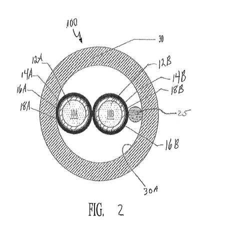
[0010] Figure 2 is a cross-section view of an exemplary AC cable 100 in
accordance with
the present invention.
[0011] Fig. 3A is a side view of an exemplary AC cable 300 in accordance
with the
present invention.
[0012] Fig. 3B is a cut-away side view of the exemplary AC cable 300
shown in Fig. 3A
in accordance with the present invention.
[0013] Fig. 4 is a cut-away side view of an exemplary AC cable 400 in
accordance with
an embodiment of the present invention.
[0014] Fig. 5 is a cross sectional view of an exemplary AC cable 500 in
accordance with
an embodiment of the present invention.
Description of Embodiments
[0015] The present invention will now be described more fully hereinafter
with reference
to the accompanying drawings, in which preferred embodiments of the invention
are shown.
This invention, however, may be embodied in many different forms and should
not be construed
as limited to the embodiments set forth herein. Rather, these embodiments are
provided so that
this disclosure will be thorough and complete, and will fully convey the scope
of the invention to
those skilled in the art. In the drawings, like numbers refer to like elements
throughout.
[0016] Fig. 1 is a cross sectional view of an exemplary electrical
conductor assembly 10
used in an AC cable. The electrical conductor assembly 10 has a generally
circular cross section
and includes a stranded or solid electrical conductor 12 having conventional
insulation layer 14
and a jacket layer 16 disposed on conventional insulation layer 14. The
electrical conductor 12,
insulation layer 14 and jacket layer 16 define an NEC type THHN or THWN
insulated
conductor where the insulation layer 14 may be PVC and jacket layer 16 may be
nylon. A
polymeric protective layer 18 is disposed on jacket layer 16 and more
particularly, is extruded
over jacket layer 16. Protective layer 18 is polypropylene, but may also be
made from
polyethylene or similar polymeric material. Protective layer 18 may also be a
foamed polymeric
material that includes air pockets filled with gasses, some or all of which
may be inert.
4
CA 02719689 2010-09-24
WO 2009/126613 PCT/US2009/039753
Protective layer 18 provides mechanical strength to resist buckling, crushing
and scuffing and
may also provide proper positioning and tensioning of a ground conductor as
described below.
The protective layer 18 may also be pliable to provide a conforming surface to
that of the inside
of the metal sheath or adjacently positioned conductor assemblies.
[0017] Fig. lA is a cross sectional view of an electrical conductor
assembly 15 including
a stranded or solid electrical conductor 12 having conventional insulation
layer 14 and a
protective layer 18. Unlike the conductor assembly 10 of Fig. 1 where the
protective layer 18 is
disposed over the jacket layer 16, the protective layer 18 of conductor
assembly 15 is disposed
over insulation layer 14. Protective layer 18 is polypropylene, but may also
be made from
polyethylene or similar polymeric material. Protective layer 18 may be a
foamed polymeric
material that includes air pockets filled with gasses, some or all of which
may be inert.
Protective layer 18 provides mechanical strength to resist buckling, crushing
and scuffing of the
conductor assembly 15.
[0018] Fig. 2 is a cross sectional view of an AC cable 100 including a
metal sheath 30
housing electrical conductor assemblies 10A, 10B and a bonding strip or strip
25. The electrical
conductor assemblies 10A-B have the same configuration as conductor assembly
10 shown in
Fig. 1. In particular, conductor assembly 10A includes electrical conductor
12A having
surrounding insulation layer 14A, jacket layer 16A and polymeric protective
layer 18A.
Similarly, conductor assembly 10B includes electrical conductor 12B having
surrounding
insulation layer 14B, jacket layer 16B and polymeric protective layer 18B. The
metal sheath or
armor 30 has a generally circular cross section with a minimum thickness of
about 0.025 inches.
Sheath 30 may be formed from a flat metal strip that is helically wrapped, the
edges of which
interlock to form a series of "S" shaped convolutions along the length of the
cable. In this
manner, the metal sheath allows cable 100 to have a particular bend radius
sufficient for
installation within a building or structure. The sheath may also be formed
into shapes other than
generally circular such as, for example, rectangles, polygons, ovals and the
like. Thus, metal
sheath 30 provides a hollow area within which conductor assemblies 10A-B and
bonding strip 25
are housed while providing a protective covering for the conductors. The
electrical conductor
assemblies 10A, 10B are cabled together wherein the conductors are twisted
longitudinally
together with a left-handed lay in accordance with the lay requirements
defined in Section 5.5 of
CA 02719689 2010-09-24
WO 2009/126613 PCT/US2009/039753
UL Standard 4. Bonding strip 25 may be a strip of thin bare aluminum which is
laid
longitudinally along the cable 100 in intimate contact with the interior
surface 30A of metal
armored sheath 30. The bonding strip is not cabled with conductor assemblies
10A-B and is
parallel with the metal sheath 30 to form an electrically conductive path
having the capacity to
safely conduct fault current likely to be imposed on cable 100.
[0019] Fig. 3A is a side plan view of cable 300 illustrating metal sheath
30 sized to
receive electrical conductor assemblies 10A, 10B and 10C as well as bonding
strip 25. Similar
to conductor assembly 10 of Fig. 1, each of the conductor assemblies 10A-C
comprises electrical
conductors 12A-C insulating layers 14A-C, jacket layers 16A-C and protective
layers 18A-C,
respectively. One of the conductor assemblies 10A, 10B or 10C may be a ground
conductor
where the respective insulating layer 14A-C ensures that the ground conductor
does not come in
contact with metal sheath 30. The conductor assemblies 10A-C are cabled
together and bonding
strip 25 is laid longitudinally along the axis of the cabled conductor
assemblies. This may be
seen more clearly in Fig. 3B which is a view of cable 300 where a portion of
sheath 30 is cut-
away. In particular, conductor assemblies 10A-C are cabled and bonding strip
25 is laid
longitudinally along the length of cable 300 and is not cabled with conductor
assemblies 10A-C.
The metal strips which are helically wrapped and interlocked to form a series
of "S" shaped
convolutions which comprise sheath 30 define a series of crowns 21 and troughs
22 along the
length of cable 300. Because bonding strip 25 is laid longitudinally within
sheath 30, bonding
strip 25 contacts the series of troughs 22 along the interior surface 30A of
sheath 30 along the
length of cable 300. In this manner, bonding strip 25 is in direct contact
with the interior surface
30A of metal armored sheath 30 to form an electrically conductive path having
the capacity to
safely conduct fault current likely to be imposed on cable 300.
[0020] Fig. 4 is a side view of AC cable 400 where a portion of sheath 30
is cut-away.
Metal sheath 30 is sized to receive electrical conductor assemblies 10A, 10B
and 10C as well as
bonding strip 25. Similar to conductor assembly 10 of Fig. 1, each of the
conductor assemblies
10A-C comprises electrical conductors 12A-C insulating layers 14A-C, jacket
layers 16A-C and
protective layers 18A-C, respectively. One of the conductor assemblies 10A,
10B or 10C may
be a ground conductor where the respective insulating layer 14A-C ensures that
the ground
conductor does not come in contact with metal sheath 30. In this embodiment,
conductor
6
CA 02719689 2010-09-24
WO 2009/126613 PCT/US2009/039753
assemblies 10A-C are not cabled together, but rather extend longitudinally
along the metal
sheath 30 such that a longitudinal axis of the conductors is parallel to a
longitudinal axis of
sheath 30. Bonding strip 25 is laid longitudinally along the axis of the
cabled conductor
assemblies 10A-C such that the conductor assemblies 10A-C and the bonding
strip 25 are
generally parallel along the respective longitudinal axes. Bonding strip 25
contacts the interior
surface 30A of sheath 30 along the series of troughs 22 formed by the
helically wrapped "S"
configurations. In this manner, bonding strip 25 is in direct contact with the
interior surface 30A
of metal armored sheath 30 to form an electrically conductive path having the
capacity to safely
conduct fault current likely to be imposed on cable 400.
[0021] Fig. 5 is a cross sectional view of AC cable 500 having metal
sheath 30 sized to
receive a plurality of electrical conductor assemblies 10A-E. Since AC cable
can only have up
to four (4) electrical conductors and cable 500 has five (5) conductor
assemblies (10A-E), one of
the conductor assemblies 10A-E must be a ground conductor. For ease of
explanation, conductor
assembly 10E is designated as the ground conductor, but any of the assemblies
10A-E may be
the ground conductor. Each of the conductor assemblies 10A-E has the same
configuration as
the conductor assemblies 10 described above including conductors 12A-E,
insulation layers 14A-
E, jacket layers 16A-E and protective layers 18A-E respectively. Again, each
of the protective
layers 18A-E is constructed from a polymeric material adapted for coaxial
extrusion. The
conductor assemblies 10A-E are cabled together and bonding strip 25 is laid
longitudinally along
the axis of the cabled conductor assemblies such that bonding strip 25 is in
contact with the
interior surface 30A of metal sheath 30. Conductor assembly 10E is a ground
conductor and is
insulated from contact with bonding strip 25 and the interior surface 30A of
metal sheath 30.
[0022] While the present invention has been disclosed with reference to
certain
embodiments, numerous modifications, alterations and changes to the described
embodiments
are possible without departing from the sphere and scope of the present
invention, as defined in
the appended claims. Accordingly, it is intended that the present invention
not be limited to the
described embodiments, but that it has the full scope defined by the language
of the following
claims, and equivalents thereof
7