Note: Descriptions are shown in the official language in which they were submitted.
CA 02719731 2010-09-24
A9138MT
DESCRIPTION
INFORMATION RECORDING MEDIUM,
REPRODUCING DEVICE AND REPRODUCING METHOD
TECHNICAL FIELD
[0001] The present invention relates to a multilayer
recording medium with a number of recording layers and also
relates to an apparatus and method for performing a read
operation on such a multilayer recording medium.
BACKGROUND ART
[0002] To increase the storage capacities of optical discs,
the size of a light beam spot to be condensed by an objective
lens provided for an optical head has been decreased year
after year by increasing the NA (numerical aperture) of the
objective lens and shortening the wavelength X of the light
emitted from a light source. Meanwhile, to further increase
the storage capacities of optical disc media, a multilayer
recording medium with multiple recording layers has also been
proposed just lately.
1
CA 02719731 2010-09-24
A9138MT
[0003] In a conventional multilayer recording medium, a
number of spacers with mutually different thicknesses are
alternately stacked between its multiple recording layers,
thereby minimizing a multiple reflection (see Patent Document
No. 1, for example). FIG. 2 illustrates a conventional
multilayer recording medium as disclosed in Patent Document
No. 1.
[0004] In the multilayer recording medium shown in FIG. 2,
eight information recording layers LO, L1, ... and L7 are
stacked in this order one upon the other so that the LO layer
is located most distant from the scanner (i.e., optical
pickup) and that the L7 layer is located closet to the pickup,
and seven spacers with thicknesses tO through t6 are
interposed between those information recording layers. Also,
to make the intensity reflectances R(n+2) and R(n+3) of the
respective reflective films of L(n+2) and L(n+3) layers, which
are located shallower than an L(n) layer, satisfy
R(n+2)xR(n+3)<0.01,
the inequality tl>tO>t3=t5>t2=t4=t6 needs to be met. That
is why settings can be made so that t6=t4=t2 and t5= t3, and
2
CA 02719731 2010-09-24
A9138MT
therefore, the number of different kinds of spacers to provide
to reduce the multiple reflection can be reduced from seven to
four.
[0005] On the other hand, when such a conventional
multilayer recording medium is scanned, the deepest layer
(i.e., the layer farthest away from the optical pickup) and
the shallowest layer (i.e., the layer closest to the optical
pickup) will transmit the incoming laser beam at mutually
different transmittances, thus making the best readout powers
on the respective recording layers different from each other
in some cases (see Patent Document No. 2).
CITATION LIST
PATENT LITERATURE
[0006]
Patent Document No. 1: Japanese Patent Application Laid-
Open Publication No. 2006-40456
Patent Document No. 2: Japanese Patent Application Laid-
Open Publication No. 2005-122862
3
CA 02719731 2010-09-24
A9138MT
SUMMARY OF INVENTION
TECHNICAL PROBLEM
[0007] Considering the properties of the respective
recording layers, if information was read from any of those
recording layers with more than predetermined readout power,
the data stored there might deteriorate. That is why the
readout power should be at most equal to the predetermined
readout power. However, in a situation where the storage
capacity per disc were increased by simply increasing the
number of recording layers stacked, the more distant from the
scanner a given recording layer is, the greater the number of
recording layers stacked under itself. Thus, the read
operation on such a distant layer should be carried out with
light that has already gone through a lot of recording layers.
For example, in a multilayer optical disc in which LO, L1 , ...
and L7 layers are stacked one upon the other in this order,
the reflectance TR(LO) of the deepest one (LO layer) of those
layers stacked is given by the following Equation (1):
TR(L0) =ROxT12xT22xT32xT42xT52xT62xT72 (1)
where TO through T7 represent the transmittances of the
4
CA 02719731 2010-09-24
A9138MT
respective layers and RO through R7 represent their own
reflectances.
[00081 As can be seen from this Equation (1), the
reflectance of the LO layer is obtained by multiplying
together the squares of the respective transmittances of the
other shallower layers. Also, supposing the reflectances RO
through R7 of the recording layers themselves are constant,
the deeper a given recording layer, the lower the reflectance
of that layer LO, L1, ... or L7. If the reflectance of a given
recording layer decreased, the intensity of the light
returning from that layer to the photodetector would decrease,
thus also decreasing the SNR and making it more difficult to
get a read operation done as intended. Thus, to overcome such
a problem, according to a conventional approach, the
reflectances of the respective layers stacked are increased
with the depth of that layer (i.e., the deepest one of the
recording layers has a higher reflectance than any other
recording layer) so that the incoming light is reflected
substantially uniformly by those layers stacked. If a given
optical disc has just two layers, then the optical structure
CA 02719731 2010-09-24
A9138MT
of that disc can be determined easily by striking an adequate
balance between them. In an optical disc with three or more
layers, however, it is more and more often necessary to
increase the transmittance of a shallow layer and decrease the
reflectance of a deep layer, thus making it increasingly
difficult to arrange the respective recording layers as
intended. Such a problem is particularly noticeable on a
rewritable optical disc, in which it is difficult to ensure a
good SNR for its recording film. In scanning such an optical
disc with low reflectance, the SNR could be increased by
raising the readout power during a read operation and
increasing the intensity of the light returning from each
recording layer. However, the lower the reflectance of a
given recording layer is, the more and more often the
following problem will arise if the readout power is increased
to ensure sufficient SNR. As a result, according to a
conventional technique, it has been actually difficult to
ensure a sufficiently good SNR just by increasing the readout
power.
[0009] For example, in an optical disc consisting of eight
6
CA 02719731 2010-09-24
A9138MT
recording layers LO through L7, the power P(LO) of the light
that irradiates the LO layer is represented by the following
Equation (2):
P(LO)= PwxTlxT2xT3xT4xT5xT6xT7 (2)
where Pw represents the readout power of a laser beam that has
been radiated from an optical pickup and incident on the
optical disc.
[0010] As can be seen from this Equation (2), the power of
the light that irradiates a deep layer is obtained by
multiplying together the respective transmittances T of the
other shallower layers and the readout power Pw. T is smaller
than one. That is why the deeper a given recording layer, the
lower the power of the light that irradiates that layer during
a read operation, which means that the deeper the given
recording layer, the less likely the stored data will
deteriorate even when irradiated with readout radiation.
Consequently, theoretically speaking, the deeper the given
recording layer, the higher the readout power can be. It
should be beneficial in terms of SNR to increase the readout
power according to the depth of a given recording layer in a
7
CA 02719731 2010-09-24
A9138MT
multilayer optical disc in which the deeper a given recording
layer, the lower the reflectance tends to be as represented by
Equation (1). If the readout power is simply increased to
ensure a good enough SNR, a read operation can certainly be
carried out safely on such a deep layer without deteriorating
the data stored there. However, in a situation where the
control operation lost stability due to the impact applied
externally to the optical disc drive or the presence of a
scratch on the given disc, the incoming light could strike on
another layer by mistake (i.e., an unintentional layer-to-
layer jump could happen). In that case, the data stored in
that wrong layer could deteriorate. For that reason, it is
usually difficult to perform a read operation with the readout
power increased so much as to ensure a good enough SNR.
[0011] It is therefore an object of the present invention
to provide a multilayer information recording medium in which
even if such an unintentional layer-to-layer jump has
happened, the data stored in that recording layer that has
been reached by mistake never deteriorates. Another object of
the present invention is to provide an optical disc drive that
8
CA 02719731 2010-09-24
A9138MT
can perform a read operation on such a multilayer optical disc
with a good enough SNR and at a low error rate.
SOLUTION TO PROBLEM
[0012] An information recording medium according to the
present invention is a multilayer information recording
medium including a number of information recording layers on
which information is stored. At least one of those
information recording layers uses different readout power to
read information than the other information recording layers.
And a base thickness between each pair of adjacent ones of
the information recording layers is equal to or greater than
a predetermined thickness.
[0013] In one preferred embodiment, the base thickness is
a thickness at which the intensity of light decreases to a
predefined degree or more due to aberration.
[0014] Another information recording medium according to
the present invention includes at least three information
recording layers. If the readout power of a laser beam in
reading information from an nth one L(n) (where n is an
9
CA 02719731 2010-09-24
A9138MT
integer that is equal to or greater than zero) of the
information recording layers, which are counted sequentially
from one of the information recording layers that is located
most distant from the data side of the information recording
medium, is identified by Pw(n), and if the readout power of
the laser beam in reading information from an (n+a) th one
L(n+a) of the information recording layers is identified by
Pw(n+a) (where a is an integer that satisfies n + a ? 0 and
aO0), then a base thickness between each pair of adjacent ones
of the information recording layers is determined so that the
intensity of the light when the information recording layer
L(n+a) is irradiated with a laser beam having the readout
power Pw(n) becomes equal to or lower than that of the light
when the information recording layer L(n+a) is irradiated with
a laser beam having the readout power Pw(n+a).
[0015] Still another information recording medium
according to the present invention includes at least three
information recording layers. If the readout power of a laser
beam in reading information from an nth one L(n) (where n is
an integer that is equal to or greater than zero) of the
CA 02719731 2010-09-24
A9138MT
information recording layers, which are counted sequentially
from one of the information recording layers that is located
most distant from the data side of the information recording
medium, is identified by Pw(n), and if the readout power of
the laser beam in reading information from an (n+a) th one
L(n+a) of the information recording layers is identified by
Pw(n+a) (where a is an integer that satisfies n + a ? 0 and
a#0), and if the base thickness between the information
recording layers L(n) and L(n+a) is identified by D, then the
information recording medium satisfies
10OxPw (n) /Pw (n+a) ?-0. 1238xD2-2.772xD+106.56, and
Pw (n) Pw (n+a) .
[0016] A reading method according to the present invention
is a method for reading information from the information
recording medium described above. The method includes the
steps of: irradiating the information recording layer L(n)
with a laser beam having the readout power Pw(n) in reading
information from the information recording layer L(n); and
irradiating the information recording layer L(n+a) with a
laser beam having the readout power Pw(n+a) in reading
11
CA 02719731 2010-09-24
A9138MT
information from the information recording layer L(n+a).
[0017] A reading apparatus according to the present
invention is an apparatus for reading information from the
information recording medium described above. The apparatus
includes an irradiating section for irradiating the
information recording medium with a laser beam. The
irradiating section irradiates the information recording layer
L(n) with a laser beam having the readout power Pw(n) in
reading information from the information recording layer L(n).
The irradiating section irradiates the information recording
layer L(n+a) with a laser beam having the readout power
Pw(n+a) in reading information from the information recording
layer L (n+a) .
[0018] An information recording medium making method
according to the present invention is a method of making an
information recording medium with k information recording
layers (where k is an integer that is equal to or greater than
three). The method includes the steps of: forming the k
information recording layers, from which information is
retrievable using a laser beam with a wavelength of 400 nm to
12
CA 02719731 2010-09-24
A9138MT
410 nm through an objective lens with a numerical aperture of
0.84 to 0.86, on a substrate with a thickness of 1.1 mm;
forming (k-1) spacer layers between the information recording
layers; and forming a protective coating with a thickness of
0.1 mm or less on the kth one of the information recording
layers as counted from the substrate. The step of forming
information recording layers includes: making either
concentric or spiral tracks on one of two groups of the
information recording layers that are either odd-numbered or
even-numbered as counted from the substrate so that the laser
beam scans that group of information recording layers from
some outer radial location on the information recording medium
toward the inner edge thereof; and making either concentric or
spiral tracks on the other group of the information recording
layers that are either even-numbered or odd-numbered so that
the laser beam scans that group of information recording
layers from some inner radial location on the information
recording medium toward the outer edge thereof. If the
readout power of the laser beam in reading information from an
nth one L(n) (where n is an integer that is equal to or
13
CA 02719731 2010-09-24
A9138MT
greater than zero) of the information recording layers, which
are counted sequentially from one of the information recording
layers that is located most distant from the data side of the
information recording medium, is identified by Pw(n), and if
the readout power of the laser beam in reading information
from an (n+a) th one L(n+a) of the information recording
layers, which are counted sequentially from the most distant
information recording layer from the data side of the
information recording medium, is identified by Pw(n+a) (where
a is an integer that satisfies n + a ? 0 and a*0), and if the
base thickness between the information recording layers L(n)
and L(n+a) is identified by D, then the information recording
medium satisfies
100xPw (n) /Pw (n+a) ?-0. 1238xD2-2. 772xD+106.56, and
Pw (n) :Pw (n+a) .
ADVANTAGEOUS EFFECTS OF INVENTION
[0019] According to the present invention, all of the
recording layers have respectively different best readout
powers or only some of the recording layers have a different
14
CA 02719731 2010-09-24
A9138MT
readout power from the others, and the base thickness between
the respective recording layers is equal to or greater than a
predetermined thickness. Thus, by adopting the arrangement of
the present invention, the readout powers for the respective
recording layers can be determined so as not to deteriorate or
erase stored data by mistake even if an unintentional layer-
to-layer jump has happened.
BRIEF DESCRIPTION OF DRAWINGS
[0020]
FIG. 1 illustrates an exemplary structure for a recording
medium as a specific preferred embodiment of the present
invention.
FIG. 2 illustrates an exemplary structure for a recording
medium.
FIG. 3 shows how the light intensity changes with the
base thickness in a preferred embodiment of the present
invention.
FIG. 4 shows how the light intensity may change with the
base thickness in the recording medium as a preferred
CA 02719731 2010-09-24
A9138MT
embodiment of the present invention.
FIG. 5 shows, using an approximation equation, the
relation between the base thickness and the light intensity in
a preferred embodiment of the present invention.
FIG. 6 illustrates a reading apparatus as a preferred
embodiment of the present invention.
FIG. 7 illustrates the structure of a multilayer disc as
a preferred embodiment of the present invention.
FIG. 8 illustrates the structure of a single-layer disc
as a preferred embodiment of the present invention.
FIG. 9 illustrates the structure of a dual-layer disc as
a preferred embodiment of the present invention.
FIG. 10 illustrates the structure of a three-layer disc
as a preferred embodiment of the present invention.
FIG. 11 illustrates the structure of a four-layer disc as
a preferred embodiment of the present invention.
FIG. 12 illustrates the physical structure of an optical
disc as a preferred embodiment of the present invention.
FIG. 13(a) illustrates an exemplary 25 GB BD as a
preferred embodiment of the present invention and FIG. 13(b)
16
CA 02719731 2010-09-24
A9138MT
illustrates an optical disc as a preferred embodiment of the
present invention that has a higher storage density than the
25 GB BD.
FIG. 14 illustrates how a series of recording marks on a
track is irradiated with a light beam in a preferred
embodiment of the present invention.
FIG. 15 is a graph showing how the OTF changes with the
shortest recording mark on a disc with a storage capacity of
25 GB as a preferred embodiment of the present invention.
FIG. 16 shows an example in a preferred embodiment of the
present invention in which the spatial frequency of the
shortest mark (2T) is higher than an OTF cutoff frequency and
in which a 2T read signal has an amplitude of zero.
DESCRIPTION OF EMBODIMENTS
[0021] Hereinafter, preferred embodiments of a multilayer
information recording medium, reading method and reading
apparatus according to the present invention will be
described with reference to the accompanying drawings.
17
CA 02719731 2010-09-24
A9138MT
(EMBODIMENT 1)
[0022] FIG. 1 illustrates the structure of a multilayer
information recording medium (optical disc) 100 as a specific
preferred embodiment of the present invention. In the
following description, any pair of components shown in both of
FIGS. 1 and 2 and having substantially the same function will
be identified by the same reference numeral and a detailed
description thereof will be omitted herein.
[0023] The multilayer information recording medium 100 has
three or more recording layers on which information can be
stored. In FIG. 1, LO through L3 denote respective recording
layers, and t0 through t2 denote base thicknesses between the
respective recording layers. As a spacer layer is inserted
between each pair of recording layers, the "base thickness"
means the thickness of the spacer layer. Also, PwO through
Pw3 denote the best readout powers for the respective
recording layers LO to L3.
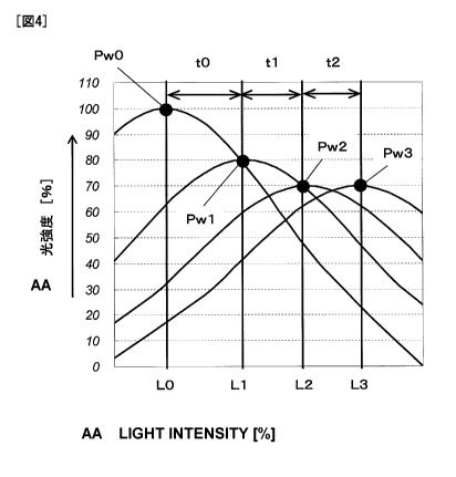
[0024] FIG. 3 shows how the intensity of light changes with
the base thickness. In this case, the "light intensity"
represents the power of light falling on a unit area of a
18
CA 02719731 2010-09-24
A9138MT
recording layer. In FIG. 3, a light intensity associated with
a base thickness, at which the laser beam could be focused
most efficiently on the target recording layer, is supposed to
be 100%. As shown in FIG. 3, if the base thickness of a
recording medium changes, an objective lens built in an
optical pickup comes to have a value that has deviated from
the designed one, thus producing a spherical aberration and
causing a variation in light intensity, which is almost
equivalent to a variation in readout power. That is to say,
for a recording layer, a variation in light intensity due to
the change of the base thickness and a variation in the
optical power of the laser beam at a constant base thickness
mean substantially the same.
[0025] Also, the relation between the base thickness and
the light intensity changes according to the wavelength of the
laser beam used. In FIG. 3, shown is how the light intensity
varied according to the base thickness in a situation where a
blue laser beam was used on a Blu-ray Disc (BD) at an NA of
0.85 and at a wavelength of 405 nm, for example. This
variation in light intensity is substantially proportional to
19
CA 02719731 2010-09-24
A9138MT
the third power of NA and the wavelength. That is to say, by
setting the NA to be high, even if the base thickness varies
just slightly, the light intensity will decrease significantly.
In that case, even if the interval between recording layers is
narrow, the variation in light intensity can still be
significant.
[00261 Specifically, if a multilayer disc has an interval
of 20 to 30 u m between its adjacent layers and if the
thickest recording layer thereof has a base thickness of
approximately 100 u m and if any other additional recording
layers are provided so as to have thicknesses of smaller than
100 u m, the light intensity will vary by about 30% even
between two layers that are spaced apart from each other by
approximately 10 u m or more as long as NA is higher than 0.8.
For example, if there is an interval (i.e., a base thickness)
of 10 u m between LO and L1 layers, the light intensity will
decrease to 70% even when an unintentional layer-to-layer jump
to the Ll layer has happened by mistake while the LO layer is
being scanned. That is why even if the readout power for the
LO layer was defined to be 1.42 (=1/0.7) times as high as the
CA 02719731 2010-09-24
A9138MT
power for the Ll layer, no damage would be done on the Ll
layer.
[0027] Such a decrease in light intensity is proportional
to the third power of NA and the wavelength of the light beam.
Thus, as long as NA is equal to or greater than 0.85, a more
significant decrease in light intensity than the one shown in
FIG. 3 will be caused. As a result, even if the base
thickness remains the same, a more significant effect can be
achieved and a greater readout power can be defined for the LO
layer. The same can be said about the wavelength. That is to
say, the shorter the wavelength, the more significant that
effect will be.
[0028] As can be seen, in a situation where respective
recording layers have different best readout powers, if an
unintentional layer-to-layer jump has happened, the readout
power for the recording layer reached by mistake as a result
of the layer-to-layer jump may be higher than the previous
one, and the data stored there could deteriorate. To avoid
such a problem, it is effective to set the base thickness
between each pair of adjacent recording layers to a
21
CA 02719731 2010-09-24
A9138MT
predetermined value or more to take advantage of a decrease
in light intensity due to a variation in base thickness.
Thus, according to this preferred embodiment, the base
thickness between each pair of adjacent recording layers is
determined by reference to such a relation between the base
thickness and the light intensity. As for readout powers for
reading information, at least one recording layer requires a
different readout power from the other recording layers. But
such a difference is dealt with by setting the base thickness
between each pair of adjacent recording layers to be equal to
or greater than a predetermined thickness. As used herein,
the "predetermined thickness" is a thickness at which the
intensity of light decreases to a predefined degree or more
due to aberration. This point will be described in further
detail later.
[0029] Hereinafter, it will be described with reference to
FIG. 4 how to determine the base thickness according to this
preferred embodiment by reference to the relation between the
base thickness and the light intensity. FIG. 4 shows how the
light intensity changes with the base thickness.
22
CA 02719731 2010-09-24
A9138MT
[0030] In FIG. 4, when information is read from the
recording layer LO, the laser beam is supposed to have the
best readout power PwO and the light intensity when the laser
beam is focused on the recording layer LO is supposed to be
100%.
[0031] On the other hand, when information is read from
the recording layers L1, L2 and L3, the laser beam is
supposed to have best readout powers Pwl, Pw2 and Pw3,
respectively. In this case, the readout powers for the
respective recording layers are normalized so that Pw0 = 100,
Pwl = 80, and Pw2 = Pw3 = 70 are satisfied. For example, when a
laser beam with the readout power Pwl is focused on the
recording layer L1, the light intensity is represented by 80%.
Also, the base thickness is determined so that even if the
laser beam with the readout power PwO is focused on the
recording layer Ll, the light intensity becomes equal to or
smaller than 80%. That is to say, the base thickness is
determined so that that light intensity becomes equal to or
smaller than the one in a situation where a laser beam with
the readout power Pwi is focused on the recording layer Ll.
23
CA 02719731 2010-09-24
A9138MT
[0032] In the same way, when a laser beam with the readout
power Pw2 is focused on the recording layer L2, the light
intensity is represented by 70%. Also, the base thickness is
determined so that even if the laser beam with the readout
power Pwl is focused on the recording layer L2, the light
intensity becomes equal to or smaller than 70%. That is to
say, the base thickness is determined so that that light
intensity becomes equal to or smaller than the one in a
situation where a laser beam with the readout power Pw2 is
focused on the recording layer L2.
[0033] In this manner, by utilizing the relation shown in
FIG. 3, the base thickness between each pair of adjacent
recording layers can be determined appropriately according to
the readout powers for the recording layers.
[0034] The disclosed invention may be modified in numerous
ways and may assume many embodiments other than those
specifically described above without departing from the
spirit of the present invention. For example, the base
thickness may be determined so that the light intensity on the
recording layer that has been reached accidentally as a result
24
CA 02719731 2010-09-24
A9138MT
of an unintentional layer-to-layer jump either agrees with, or
becomes smaller than, the best light intensity for that
recording layer.
[0035] Also, in the preferred embodiment described above,
the base thickness is supposed to be determined so that the
light intensity on the recording layer that has been reached
accidentally as a result of an unintentional layer-to-layer
jump becomes equal to or smaller than the best light intensity
for that recording layer. However, the base thickness may
also be determined so that the light intensity on that
unexpected recording layer becomes smaller than a light
intensity at which data stored on that recording layer starts
to deteriorate.
[0036] Furthermore, in the preferred embodiment described
above, the base thickness between each pair of adjacent
recording layers is determined by reference to the relation
between the variation in base thickness and the light
intensity. However, the base thickness may also be
determined by using a simple approximation equation. For
example, as for a Blu-ray Disc (BD) that uses a blue laser
CA 02719731 2010-09-24
A9138MT
beam, the following approximation Equations (3) and (4) are
obtained based on the relation between the base thickness, the
light intensity and the readout power, and the base thickness
can be determined by those equations. FIG. 5 shows the
relation between the base thickness and the light intensity by
the following approximation equation:
S=-0. 1238 x d2+2.772 x d+106.56 (3)
where S represents the light intensity [%] and C. represents a
variation in base thickness [aim] from a value associated with
a light intensity of 100% and is a positive integer.
[0037] Suppose the readout power of the laser beam for
reading information from an nth one L(n) of the information
recording layers, which are counted sequentially from the most
distant recording layer from the data side surface (i.e., the
upside shown in FIG. 1) of the optical disc 100, is identified
by Pw(n), where n is an integer that is equal to or greater
than zero. For example, the most distant (i.e., the deepest)
recording layer from the data side may be identified by L(0)
and its readout power PwO may be identified by Pw(0). On the
other hand, the readout power of the laser beam for reading
26
CA 02719731 2010-09-24
A9138MT
information from the (n+a) th information recording layer
L(n+a) is identified by Pw(n+a), where a is an integer that
satisfies n + a > 0 and a#0 . For instance, if n = 0 and a = 1,
then the (n+a) th layer will be the recording layer L1.
[0038] In this case, even if the readout power Pw(n) is
higher than the readout power Pw(n+a), the light intensity
when the information recording layer L(n+a) is irradiated with
the laser beam with the readout power Pw(n) is defined to be
equal to or smaller than the light intensity when the
information recording layer L(n+a) is irradiated with the
laser beam with the readout power Pw(n+a).
[0039] In the following Equation (4), if the readout power
for one recording layer that is located more distant from the
data side is lower than the power for the other layer, then a
becomes a positive integer. On the other hand, if the readout
power for the one recording layer that is located more distant
from the data side is higher than the power for the other
layer, then a becomes a negative integer. In the latter case,
the recording layer L(n+a) will be located more distant from
the data side than the recording layer L(n) is.
27
CA 02719731 2010-09-24
A9138MT
[0040] The base thickness D between the information
recording layers L(n) and L(n+a) can be calculated by:
100xPw (n) /Pw (n+a) =-0. 1238xD2-2.772xD+106. 56 (4)
where Pw(n) < Pw(n+a) and Pw(n)/Pw(n+a) is expressed in
percent. For example, if Pw(n) = Pw(n+a) (i.e., if the
Pw(n)/Pw(n+a) ratio is one), the left side of Equation (4) is
100%. Meanwhile, n is an integer that is equal to or greater
than zero and a is an integer that satisfies n + a ?0 and aO0.
[0041] The base thickness D is determined so that the left
side of Equation (4) represents an appropriate ratio. If a is
a negative integer and if the readout power Pw(n+a) is greater
than the readout power Pw(n), then the light intensity when
the information recording layer L(n) is irradiated with a
laser beam with the readout power Pw(n+a) may be equal to the
light intensity when information recording layer L(n) is
irradiated with a laser beam with the readout power Pw(n).
[0042] On the other hand, if a is a negative integer and if
the readout power Pw(n+a) is greater than the readout power
Pw(n), then the light intensity when the information recording
layer L(n) is irradiated with a laser beam with the readout
28
CA 02719731 2010-09-24
A9138MT
power Pw(n+a) may be equal to or smaller than the light
intensity when information recording layer L(n) is irradiated
with a laser beam with the readout power Pw(n). The base
thickness D that satisfies such a condition is obtained by the
following Inequality (5), which is a modified version of
Equation (4) :
100xPw (n) /Pw (n+a) 2-!:-0. 1238xD2-2. 772xD+106.56 (5)
(EMBODIMENT 2)
[0043] FIG. 6 illustrates a configuration for a reading
apparatus 400 according to the present invention. The reading
apparatus 400 is an apparatus for reading information from an
optical disc 100.
[0044] The reading apparatus includes an optical pickup 402,
a semiconductor laser control section 403 and a servo
processing section 404 for controlling the optical pickup 402,
a read signal processing section 405 for processing the read
signal supplied from the optical pickup, and a central
processing unit (CPU) section 406 for controlling multiple
components included in this reading apparatus 400.
29
CA 02719731 2010-09-24
A9138MT
[0045] In response to a control signal supplied externally
from a computer (not shown), the CPU section 406 controls the
semiconductor laser control section 403, the servo processing
section 404 and the read signal processing section 405.
[0046] The semiconductor laser control section 403 makes
settings on readout power and RF signal superposition, and
gets a laser beam emitted from the optical pickup
(corresponding to the "irradiating section") 402 with
predetermined laser power and incident on the optical disc 100.
Specifically, in reading information from the information
recording layer L(n), the optical pickup 402 irradiates the
information recording layer L(n) with a laser beam with a
readout power Pw(n). On the other hand, in reading
information from the information recording layer L(n+a), the
optical pickup 402 irradiates the information recording layer
L(n+a) with a laser beam with a readout power Pw(n+a).
[0047] The servo processing section performs a tracking
control and a focus control using the detection signals
generated by the optical pickup 402, thereby controlling the
optical pickup 402 so that the optical pickup 402 can perform
CA 02719731 2010-09-24
A9138MT
focusing and tracking operations accurately on the information
recording medium 100.
[0048] The read signal processing section 405 performs data
read signal processing and wobble signal processing, thereby
reading data and physical addresses and performing other kinds
of processing.
[0049] A recording medium normally has an area where
various kinds of information about the recording medium is
stored. Thus, the optical disc drive usually recognizes the
type of a given recording medium by reference to the
information that has been retrieved from that area and makes
setting so as to generate a predetermined readout power.
However, in some multilayer recording media, the readout
powers sometimes need to be changed for one recording layer
after another. That is why if an unintentional layer-to-layer
jump has happened by mistake while such a multilayer recording
medium is scanned, then the readout power for the recording
layer reached by mistake as a result of the layer-to-layer
jump could be higher than the previous one, thus possibly
deteriorating the data stored there.
31
CA 02719731 2010-09-24
A9138MT
[0050] As a means for avoiding such a problem, it will be
effective to determine the base thickness between each pair of
adjacent recording layers according to the type of the given
recording medium recognized and then set the readout powers
for the respective recording layers.
[0051] That is why according to the magnitude of decrease
in light intensity due to a variation in base thickness
between each pair of adjacent recording layers, readout powers
for the respective recording layers are determined.
[0052] It is possible to derive the proportionality between
readout powers for the respective recording layers based on
the base thickness between each pair of adjacent recording
layers by reference to the relation shown in FIG. 3. And the
readout powers for the respective recording layers are
determined so as to meet the appropriate proportionality
described above. For example, the proportionality shown in
FIG. 4 may be adopted.
[0053] For example, once the type of the given recording
medium has been recognized, the base thickness between each
pair of adjacent recording layers of that recording medium can
32
CA 02719731 2010-09-24
A9138MT
be determined. Thus, information about proper light
intensities for the respective recording layers may be stored
in a memory (not shown) in the CPU section 406. When the type
of the given recording medium is recognized, that light
intensity information may be retrieved from the memory of the
CPU section. The semiconductor laser control section 403 sets
the readout power according to the base thickness thus
determined, thereby irradiating each recording layer with a
laser beam with an appropriate light intensity. Alternatively,
information about appropriate readout powers for the
respective recording layers could be stored in the memory of
the CPU section 406.
[0054] In that case, the readout power information may be
obtained and stored by calculating readout powers by reference
to the relation between the base thickness and the light
intensity shown in FIG. 4 so that the light intensity when a
laser beam with a readout power for one recording layer is
focused unintentionally on another recording layer becomes as
high as the light intensity when a laser beam with a readout
power for the latter recording layer is focused on that
33
CA 02719731 2010-09-24
A9138MT
recording layer as intended. And when the type of the given
recording medium is recognized, the readout power may be
determined.
[0055] While the present invention has been described with
respect to preferred embodiments thereof, the disclosed
invention may be modified in numerous ways and may assume
many embodiments other than those specifically described
above without departing from the spirit of the present
invention. For example, the readout power information may
also be obtained and stored so that the light intensity when a
laser beam with a readout power for one recording layer is
focused unintentionally on another recording layer becomes
equal to or lower than the light intensity when a laser beam
with a readout power for the latter recording layer is focused
on that recording layer as intended.
[0056] Furthermore, in the preferred embodiment described
above, the readout power information is supposed to be
obtained and stored so that the light intensity on a wrong
recording layer reached by mistake as a result of an
unintentional layer-to-layer jump becomes equal to or lower
34
CA 02719731 2010-09-24
A9138MT
than an appropriate light intensity for that recording layer.
However, the readout power information may also be obtained
and stored so that the light intensity on that unexpected
recording layer becomes equal to or lower than a light
intensity at which the data stored on that recording layer
starts to deteriorate.
[0057] Alternatively, the readout power may be determined
and saved by reference to the relation between the variation
in base thickness and the light intensity as shown in FIG. 3
or 4. Still alternatively, the readout power may be
calculated by the approximation equation shown in FIG. 5 or
represented by Equation (3), (4) or (5) and then saved.
[0058] Also, readout powers that can be defined for the
respective recording layers of a recording medium could fall
within a range from a readout power that is low enough to
avoid deteriorating the quality of a read signal through a
readout power that is high enough to avoid deteriorating the
data stored there. In such a situation, the readout powers
for the respective recording layers could be determined so as
to avoid deteriorating the stored data as completely as
CA 02719731 2010-09-24
A9138MT
possible within the range of readout powers that can be set
for the respective recording layers. In a situation where the
readout power is set close to the upper limit, if an
unintentional layer-to-layer jump has happened, the
deterioration of the stored data cannot be avoided entirely
but its influence can still be minimized.
[0059) Hereinafter, an information recording medium
according to the present invention will be described in
further detail.
<Main parameters>
[0060] Although the present invention is applicable to
various types of recording media including Blu-ray Discs (BDs)
and discs compliant with other standards, the following
description will be focused on a BDs. Specifically, BDs are
classified according to the property of their recording film
into various types. Examples of those various BDs include a
BD-ROM (read-only), a BD-R (write-once), and a BD-RE
(rewritable). And the present invention is applicable to any
type of BD or an optical disc compliant with any other
36
CA 02719731 2010-09-24
A9138MT
standard, no matter whether the recording medium is a ROM
(read-only), an R (write-once) or an RE (rewritable). Main
optical constants and physical formats for Blu-ray Discs are
disclosed in "Blu-ray Disc Reader" (published by Ohmsha, Ltd.)
and on White Paper at the website of Blu-ray Disc Association
(http://www.blu-raydisc.com), for example.
[0061] Specifically, as for a BD, a laser beam with a
wavelength of approximately 405 nm (which may fall within the
range of 400 nm to 410 nm supposing the tolerance of errors is
nm with respect to the standard value of 405 nm) and an
objective lens with an NA (numerical aperture) of
approximately 0.85 (which may fall within the range of 0.84 to
0.86 supposing the tolerance of errors is 0.01 with respect
to the standard value of 0.85) are used. A BD has a track
pitch of about 0.32 u m (which may fall within the range of
0.310 to 0.330 j Um supposing the tolerance of errors is
0.010 gm with respect to the standard value of 0.320 j Um) and
has one or two recording layers. A BD has a single-sided
single-layer or a single-sided dual-layer structure on the
laser beam incident side, and its recording plane or recording
37
CA 02719731 2010-09-24
A9138MT
layer is located at a depth of 75 u m to 100 u m as measured
from the surface of the protective coating of the BD.
[0062] A write signal is supposed to be modulated by 17PP
modulation technique. Recording marks are supposed to have
the shortest mark length of 0.149 u m or 0.138 u m (which is
the length of a 2T mark, where T is one cycle of a reference
clock pulse and a reference period of modulation in a
situation where a mark is recorded in accordance with a
predetermined modulation rule), i.e., a channel bit length T
of 74.50 nm or 69.00 nm. The BD has a storage capacity of 25
GB or 27 GB (more exactly, 25.025 GB or 27.020 GB) if it is a
single-sided, single-layer disc but has a storage capacity of
50 GB or 54 GB (more exactly, 50.050 GB or 54.040 GB) if it is
a single-sided, dual-layer disc.
[0063] The channel clock frequency is supposed to be 66 MHz
(corresponding to a channel bit rate of 66.000 Mbit/s) at a
standard BD transfer rate (BD lx), 264 MHz (corresponding to a
channel bit rate of 264.000 Mbit/s) at BD 4x transfer rate,
396 MHz (corresponding to a channel bit rate of 396.000
Mbit/s) at BD 6x transfer rate, and 528 MHz (corresponding to
38
CA 02719731 2010-09-24
A9138MT
a channel bit rate of 528.000 Mbit/s) at BD 8x transfer rate.
[0064] And the standard linear velocity (which will also be
referred to herein as "reference linear velocity" or "lx") is
supposed to be 4.917 m/sec or 4.554 m/sec. The 2x, 4x, 6x and
8x linear velocities are 9.834 m/sec, 19.668 m/sec, 29.502
m/sec, and 39.336 m/sec, respectively. A linear velocity
higher than the standard linear velocity is normally a
positive integral number of times as high as the standard
linear velocity. But the factor does not have to be an
integer but may also be a positive real number. Optionally, a
linear velocity that is lower than the standard linear
velocity (such as a 0.5x linear velocity) may also be defined.
[0065] It should be noted that these parameters are those
of single-layer or dual-layer BDs already on the market, which
have a storage capacity of approximately 25 GB or
approximately 27 GB per layer. To further increase the
storage capacities of BDs, high-density BDs with a storage
capacity of approximately 32 GB or approximately 33.4 GB per
layer and three- or four-layer BDs have already been
researched and developed. Hereinafter, exemplary applications
39
CA 02719731 2010-09-24
A9138MT
of the present invention to such BDs will be described.
<Structure with multiple information recording layers>
[0066] For example, supposing the optical disc is a single-
sided disc, from/on which information is read and/or written
by having a laser beam incident on the protective coating
(cover layer) side, if two or more recording layers need to be
provided, then those multiple recording layers should be
arranged between the substrate and the protective coating. An
exemplary structure for such a multilayer disc is shown in FIG.
7. The optical disc shown in FIG. 7 has (n+l) information
recording layers 502 (where n is an integer that is equal to
or greater than zero). Specifically, in this optical disc, a
cover layer 501, (n+l) information recording layers (layers Ln
through LO) 502, and a substrate 500 are stacked in this order
on the surface on which a laser beam 505 is incident. Also,
between each pair of adjacent ones of the (n+l) information
recording layers 502, inserted as an optical buffering member
is a spacer layer 503. That is to say, the reference layer LO
may be arranged at the deepest level that is located at a
CA 02719731 2010-09-24
A9138MT
predetermined depth from the light incident surface (i.e., at
the greatest distance from the light source). Multiple
recording layers L1, L2, ... and Ln may be stacked one upon the
other from over the reference layer LO toward the light
incident surface.
[0067] In this case, the depth of the reference layer LO as
measured from the light incident surface of the multi-layer
disc may be equal to the depth (e.g., approximately 0.1 mm) of
the only recording layer of a single-layer disc as measured
from the light incident surface. If the depth of the deepest
layer (i.e., the most distant layer) is constant irrespective
of the number of recording layers stacked (i.e., if the
deepest layer of a multilayer disc is located at substantially
the same distance as the only recording layer of a single-
layer disc), compatibility can be ensured in accessing the
reference layer, no matter whether the given disc is a single-
layer one or a multilayer one. In addition, even if the
number of recording layers stacked increases, the influence of
tilt will hardly increase. This is because although the
deepest layer is affected by tilt most, the depth of the
41
CA 02719731 2010-09-24
A9138MT
deepest layer of a multilayer disc is approximately the same
as that of the only recording layer of a single-layer disc,
and does not increase in this case even if the number of
recording layers stacked is increased.
[0068] As for the beam spot moving direction (which will
also be referred to herein as a "tracking direction" or a
"spiral direction"), the optical disc may be either a parallel
path type or an opposite path type. In a disc of the parallel
path type, the spot goes in the same direction on every layer,
i.e., from some inner radial location toward the outer edge of
the disc or from some outer radial location toward the inner
edge of the disc on every recording layer.
[0069] On the other hand, in a disc of the opposite path
type, the spot moving directions are changed into the opposite
one every time the layers to scan are changed from one
recording layer into an adjacent one. For example, if the
spot on the reference layer LO goes from some inner radial
location toward the outer edge (which direction will be simply
referred to herein as "outward"), then the spot on the
recording layer L1 will go from some outer radial location
42
CA 02719731 2010-09-24
A9138MT
toward the inner edge (which direction will be simply referred
to herein as "inward"), the spot on the recording layer L2
will go outward, and so forth. That is to say, the spot on
the recording layer Lm (where m is either zero or an even
number) will go outward but the spot on the recording layer
Lm+1 will go inward. Conversely, the spot on the recording
layer Lm (where m is either zero or an even number) will go
inward but the spot on the recording layer Lm+1 will go
outward.
[0070] As for the thickness of the protective coating
(cover layer), to minimize the influence of spot distortion
due to either a decrease in focal length with an increase in
numerical aperture NA or the tilt, the protective coating may
have its thickness reduced. A numerical aperture NA is
defined to be 0.45 for a CD, 0.65 for a DVD, but approximately
0.85 for a BD. For example, if the recording medium has an
overall thickness of approximately 1.2 mm, the protective
coating may have a thickness of 10 /1 m to 200 11 m. More
specifically, a single-layer disc may include a transparent
protective coating with a thickness of approximately 0.1 mm
43
CA 02719731 2010-09-24
A9138MT
and a substrate with a thickness of approximately 1.1 mm. On
the other hand, a dual-layer disc may include a protective
coating with a thickness of approximately 0.075 mm, a spacer
layer with a thickness of approximately 0.025 mm and a
substrate with a thickness of approximately 1.1 mm. And if
the disc has three or more recording layers, the thickness(es)
of the protective coating and/or spacer layer could be further
reduced.
<Configurations for single- to four-layer discs>
[0071] FIGS. 8, 9, 10 and 11 illustrate exemplary
configurations for single-layer, dual-layer, three-layer and
four-layer discs, respectively. As described above, if the
distance from the light incident surface to the reference
layer LO is supposed to be constant, each of these discs may
have a total disc thickness of approximately 1.2 mm (but is
more preferably 1.40 mm or less if there is a label printed)
and the substrate 500 may have a thickness of approximately
1.1 mm. That is why the distance from the light incident
surface to the reference layer LO will be approximately 0.1 mm
44
CA 02719731 2010-09-24
A9138MT
in any of the examples shown in FIGS. 9 to 11. In the single-
layer disc shown in FIG. 8 (i.e., if n0 in FIG. 7), the
cover layer 5011 has a thickness of approximately 0.1 mm. In
the dual-layer disc shown in FIG. 9 (i.e., if n =l in FIG. 7),
the cover layer 5012 has a thickness of approximately 0.075 mm
and the spacer layer 5302 has a thickness of approximately
0.025 mm. And in the three-layer disc shown in FIG. 10 (i.e.,
if n=2 in FIG. 7) and in the four-layer disc shown in FIG. 11
(i . e . , if n=3 in FIG. 7), the cover layer 5013, 5014 and/or
the spacer layer 5303, 5304 may be even thinner.
[0072] Such a multilayer disc (i.e., a disc with k
recording layers, where k is an integer that is equal to or
greater than one) may be made by performing the following
manufacturing process steps.
[0073] First of all, the k recording layers, from which
information is retrievable using a laser beam with a
wavelength of 400 nm to 410 nm through an objective lens with
a numerical aperture of 0.84 to 0.86, are formed on a
substrate with a thickness of approximately 1.1 mm.
[0074] Next, (k-1) spacer layers are formed between the
CA 02719731 2010-09-24
A9138MT
recording layers. As for a single-layer disc, k =l and k -l=
0, and therefore, no spacer layers are provided.
[0075] Subsequently, a protective coating with a thickness
of 0.1 mm or less is formed on the kth one of the recording
layers as counted from the substrate (i.e., the most distant
recording layer from the substrate in a multilayer recording
medium).
[0076] In the step of forming the recording layers, when
the ith recording layer (where i is an odd number that falls
within the range of one through k) as counted from the
substrate is formed, either concentric or spiral tracks are
made so that the laser beam scans that recording layer from
some inner radial location on the disc toward the outer edge
thereof. On the other hand, when the jth recording layer
(where j is an even number that falls within the range of one
through k) as counted from the substrate is formed, either
concentric or spiral tracks are made so that the laser beam
scans that recording layer from some outer radial location on
the disc toward the inner edge thereof. As for a single-
layer disc, k= 1, and therefore, the odd number i that falls
46
CA 02719731 2010-09-24
A9138MT
within the range of one through k must be one when k =l, and
only one recording layer is provided as the ith recording
layer. Also, if k1, there is no even number j that falls
within the range of one through k, and therefore, no jth
recording layer is provided. Optionally, the light beam
scanning direction could be opposite to each other between an
odd layer and an even layer.
[0077] And if the readout power of the laser beam in
reading information from an nth one L(n) of the information
recording layers, which are counted sequentially from one of
the information recording layers that is located most distant
from the data side of the information recording medium, is
identified by Pw(n), and if the readout power of the laser
beam in reading information from an (n+a) th one L(n+a) of the
information recording layers, which are counted sequentially
from the most distant recording layer from the data side of
the information recording medium, is identified by Pw(n+a),
and if the base thickness between the information recording
layers L(n) and L(n+a) (i.e., the sum of the spacer layers
between the information recording layers L(n) and L(n+a)) is
47
CA 02719731 2010-09-24
A9138MT
identified by D,
then 100xPw(n) /Pw (n+a) ?-0.1238xD2-2.772xD+106.56, and
Pw (n) :Pw (n+a) are satisfied,
(where n is an integer that is equal to or greater than zero,
and a is an integer that satisfies n+a ?0 and aO0).
[0078] A read operation is performed on such a multilayer
disc (i.e., a disc with k recording layers, where k is an
integer that is equal to or greater than one) by a reading
apparatus that is an apparatus with the following
configuration (or the method to be described later).
[0079] The disc may include a substrate with a thickness of
approximately 1.1 mm, k recording layers on the substrate, (k-
1) spacer layers between the recording layers (there is no
spacer layer in a single-layer disc because k= 1 and therefore
k-1 = 0), and a protective coating with a thickness of 0.1 mm
or less on the kth recording layer as counted from the
substrate (i.e., the most distant recording layer in a
multilayer disc). Tracks are made on each of the k recording
layers, and various kinds of areas can be assigned to at least
one of those tracks.
48
CA 02719731 2010-09-24
A9138MT
[0080] And by irradiating the disc with a laser beam with
a wavelength of 400 nm to 410 nm using an objective lens with
a numerical aperture of 0.84 through 0.86 through the surface
of the protective coating, an optical head can read
information from any of the k recording layers.
[0081] The reading apparatus includes an irradiating means
for irradiating the information recording medium with a laser
beam. The irradiating means irradiates an nth one L(n) of
the information recording layers as counted from the most
distant recording layer from the data side of the information
recording medium with a laser beam having the readout power
Pw(n) in reading information from the information recording
layer L(n). And the irradiating means irradiates an (n+a) th
one L(n+a) of the information recording layers as counted
from the most distant recording layer from the data side of
the information recording medium with a laser beam having the
readout power Pw(n+a) in reading information from the
information recording layer L(n+a), where n is an integer
that is equal to or greater than zero, and a is an integer
that satisfies n+a?0 and a5 0.
49
CA 02719731 2010-09-24
A9138MT
[00821 Hereinafter, the physical structure of the optical
disc 100 will be described in further detail.
[00831 FIG. 12 illustrates the physical structure of an
optical disc 100 according to this preferred embodiment. On
the disklike optical disc 100, a lot of tracks 2 are arranged
either concentrically or spirally. And each of those tracks 2
is subdivided into a lot of sectors. As will be described
later, data is supposed to be written on each of those tracks
2 on the basis of a block 3 of a predetermined size.
[0084) The optical disc 100 of this preferred embodiment
has a greater storage capacity per information recording layer
than a conventional optical disc (such as a 25 GB BD) The
storage capacity is increased by increasing the storage linear
density, e.g., by shortening the mark length of recording
marks to be left on the optical disc, for example. As used
herein, "to increase the storage linear density" means
shortening the channel bit length, which is a length
corresponding to one cycle time T of a reference clock signal
(i.e., a reference cycle time T of modulation in a situation
where marks are recorded by a predetermined modulation rule).
CA 02719731 2010-09-24
A9138MT
The optical disc 100 may have multiple information recording
layers. In the following description, however, only one
information recording layer thereof will be described for
convenience sake. In a situation where there are multiple
information recording layers in the same optical disc, even if
the tracks have the same width between the respective
information recording layers, the storage linear densities
could also be different from one layer to another by uniformly
varying the mark lengths on a layer-by-layer basis.
[0085] Each track 2 is divided into a lot of blocks every
64 kB (kilobytes), which is the data recording unit. And
those blocks are given sequential block addresses. Each of
those blocks is subdivided into three subblocks, each having a
predetermined length (i.e., three subblocks form one block).
The three subblocks are assigned subblock numbers of 0, 1 and
2 in this order.
<Storage density>
[0086] Hereinafter, the storage density will be described
with reference to FIGS. 13, 14, 15 and 16.
51
CA 02719731 2010-09-24
A9138MT
[0087] FIG. 13(a) illustrates an example of a 25 GB BD, for
which the laser beam 123 is supposed to have a wavelength of
405 nm and the objective lens 220 is supposed to have a
numerical aperture (NA) of 0.85.
[0088] As in a DVD, data is also written on the track 2 of
a BD as a series of marks 120, 121 that are produced as a
result of a physical variation. The shortest one of this
series of marks will be referred to herein as the "shortest
mark". In FIG. 13(a), the mark 121 is the shortest mark.
[0089] In a BD with a storage capacity of 25 GB, the
shortest mark 121 has a physical length of 0.149 pm, which is
approximately 1/2.7 of the shortest mark of a DVD. And even
if the resolution of a laser beam is increased by changing
the parameters of an optical system such as the wavelength
(405 nm) and the NA (0.85), this value is still rather close
to the limit of optical resolution, below which recording
marks are no longer sensible for the light beam.
[0090] FIG. 14 illustrates a state where a light beam spot
has been formed on the series of recording marks on the
track. In a BD, the light beam spot 30 has a diameter of
52
CA 02719731 2010-09-24
A9138MT
about 0.39 um, which may vary with parameters of the optical
system. If the storage linear density is increased without
changing the structures of the optical system, then the
recording marks will shrink for the same spot size of the
light beam spot 30 and the read resolution will decrease.
[0091] On the other hand, FIG. 13(b) illustrates an example
of an optical disc with an even higher storage density than a
25 GB BD. But even for such a disc, the laser beam 123 is
also supposed to have a wavelength of 405 nm and the objective
lens 220 is also supposed to have a numerical aperture (NA) of
0.85. Among the series of marks 124, 125 of such a disc, the
shortest mark 125 has a physical length of 0.1115 U m (or
0.11175 um). Compared to FIG. 13(a), the spot size remains
approximately 0.39 JI m but both the recording marks and the
interval between the marks have shrunk. As a result, the read
resolution will decrease.
[0092] The shorter a recording mark, the smaller the
amplitude of a read signal to be generated when the recording
mark is scanned with a light beam. And the amplitude goes
zero when the mark length gets equal to the limit of optical
53
CA 02719731 2010-09-24
A9138MT
resolution. The inverse number of one period of these
recording marks is called a "spatial frequency" and a
relation between the spatial frequency and the signal
amplitude is called an "optical transfer function (OTF)". As
the spatial frequency rises, the signal amplitude decreases
almost linearly. And the retrievable limit frequency at
which the amplitude of the signal goes zero is called an OTF
cutoff.
[0093] FIG. 15 is a graph showing how the OTF of a BD with
a storage capacity of 25 GB changes with the shortest
recording mark length. The spatial frequency of the shortest
mark on a BD is approximately 80% of, and is rather close to,
the OTF cutoff frequency. It can also be seen that a read
signal representing the shortest mark has amplitude that is
as small as approximately 10% of the maximum detectable
amplitude. The storage capacity at which the spatial
frequency of the shortest mark on a BD is very close to the
OTF cutoff frequency (i.e., the storage capacity at which the
read signal has almost no amplitude) corresponds to
approximately 31 GB in a BD. When the frequency of the read
54
CA 02719731 2010-09-24
A9138MT
signal representing the shortest mark comes close to, or
exceeds, the OTF cutoff frequency, the limit of optical
resolution may have been reached or even surpassed for the
laser beam. As a result, the read signal comes to have
decreased amplitude and the SNR drops steeply.
[0094] That is why the high storage density optical disc
shown in FIG. 13(b) would have its storage linear density
defined by the frequency of the read signal representing the
shortest mark, which may be in the vicinity of the OTF cutoff
frequency (i.e., it is lower than, but not significantly lower
than, the OTF cutoff frequency) or higher than the OTF cutoff
frequency.
[0095] FIG. 16 is a graph showing how the signal amplitude
changes with the spatial frequency in a situation where the
spatial frequency of the shortest mark (2T) is higher than the
OTF cutoff frequency and where the 2T read signal has zero
amplitude. In FIG. 16, the spatial frequency of the shortest
mark 2T is 1.12 times as high as the OTF cutoff frequency.
<Relation between wavelength, NA and mark length>
CA 02719731 2010-09-24
A9138MT
[0096] An optical disc B with high storage density needs to
satisfy the following relation between the wavelength, the
numerical aperture, and the mark/space lengths.
[0097] Supposing the shortest mark length is TM nm and the
shortest space length is TS nm, the sum P of the shortest mark
length and the shortest space length is (TM+TS) nm. In the
case of 17 modulation, P = 2T + 2T = 4T. Using the three
parameters of the wavelength A of the laser beam (which is
405 nm 5 nm, i.e., in the range of 400 nm to 410 nm), the
numerical aperture NA (which is 0.854-0.01, i.e., in the
range of 0.84 to 0.86) and the sum P of the shortest mark
length and the shortest space length (where P = 2T + 2T = 4T in
the case of 17 modulation, in which the shortest length is 2T),
if the unit length T decreases to the point that the
inequality
P: A /2NA
is satisfied, then the spatial frequency of the shortest mark
exceeds the OTF cutoff frequency.
[0098] If NA = 0.85 and A. = 405, then the unit length T
corresponding to the OTF cutoff frequency is calculated by
56
CA 02719731 2010-09-24
A9138MT
T=405/ (2 X 0.85) /4=59.558 nm
(Conversely, if P > I /2NA is satisfied, then the spatial
frequency of the shortest mark becomes lower than the OTF
cutoff frequency).
[0099] As can be seen easily, just by increasing the
storage linear density, the SNR would decrease due to the
limit of optical resolution. That is why if the number of
information recording layers per disc were increased
excessively, then the decrease in SNR might be an
impermissible degree, considering the system margin.
Particularly around a point where the frequency of the
shortest recording mark exceeds the OTF cutoff frequency, the
SNR will start to decrease steeply.
[0100] In the foregoing description, the storage density
has been described by comparing the frequency of the read
signal representing the shortest mark to the OTF cutoff
frequency. However, if the storage density of BDs is further
increased, then the storage density (and the storage linear
density and the storage capacity) can be defined based on the
same principle as what has just been described by reference to
57
CA 02719731 2010-09-24
A9138MT
the relation between the frequency of the read signal
representing the second shortest mark (or the third shortest
mark or an even shorter recording mark) and the OTF cutoff
frequency.
<Storage density and number of layers>
[0101] A BD, of which the specifications include a
wavelength of 405 m and a numerical aperture of 0.85, may have
one of the following storage capacities per layer.
Specifically, if the spatial frequency of the shortest marks
is in the vicinity of the OTF cutoff frequency, the storage
capacity could be approximately equal to or higher than 29 GB
(such as 29.0 GB 0.5 GB or 29 GB l GB), approximately equal
to or higher than 30 GB (such as 30.0 GB 0.5 GB or 30 GB l
GB), approximately equal to or higher than 31 GB (such as 31.0
GB 0.5 GB or 31 GB 1 GB), or approximately equal to or
higher than 32 GB (such as 32.0 GB-+- 0.5 GB or 32 GB 1 GB).
[0102] On the other hand, if the spatial frequency of the
shortest marks is equal to or higher than the OTF cutoff
frequency, the storage capacity per layer could be
58
CA 02719731 2010-09-24
A9138MT
approximately equal to or higher than 32 GB (such as 32.0 GB --h
0.5 GB or 32 GB 1 GB), approximately equal to or higher than
33 GB (such as 33.0 GB 0.5 GB or 33 GB l GB), approximately
equal to or higher than 33.3 GB (such as 33.3 GB 0.5 GB or
33.3 GB l GB), approximately equal to or higher than 33.4 GB
(such as 33.4 GB 0.5 GB or 33.4 GB 1 GB), approximately
equal to or higher than 34 GB (such as 34.0 GB 0.5 GB or 34
GB l GB) or approximately equal to or higher than 35 GB (such
as 35.0 GB 0.5 GB or 35 GB l GB) .
[0103] In this case, if the storage density per layer is
33.3 GB, an overall storage capacity of approximately 100 GB
(more exactly, 99.9 GB) is realized by the three recording
layers combined. On the other hand, if the storage density
per layer is 33.4 GB, an overall storage capacity that is more
than 100 GB (more exactly, 100.2 GB) is realized by the three
recording layers combined. Such a storage capacity is almost
equal to the capacity in a situation where four recording
layers, each having a storage density of 25 GB, are provided
for a single BD. For example, if the storage density per
layer is 33 GB, the overall storage capacity is 33X3=99 GB,
59
CA 02719731 2010-09-24
A9138MT
which is just 1 GB (or less) smaller than 100 GB. On the
other hand, if the storage density per layer is 34 GB, the
overall storage capacity is 34 X 3 = 102 GB, which is 2 GB (or
less) larger than 100 GB. Furthermore, if the storage density
per layer is 33.3 GB, the overall storage capacity is 33.3 X 3
=99.9 GB, which is only 0.1 GB (or less) smaller than 100 GB.
And if the storage density per layer is 33.4 GB, the overall
storage capacity is 33.4 X 3 = 100.2 GB, which is just 0.2 GB
(or less) larger than 100 GB.
[0104] It should be noted that if the storage density were
increased significantly, then it would be difficult to perform
a read operation accurately because the shortest marks should
be read under rather severe conditions. That is why a
realistic storage density that would realize an overall
storage capacity of 100 GB or more without increasing the
storage density too much would be approximately 33.4 GB per
layer.
[0105] In this case, the optical disc may have either a
four-layer structure with a storage density of 25 GB per layer
or a three-layer structure with a storage density of 33-34 GB
CA 02719731 2010-09-24
A9138MT
per layer. If the number of recording layers stacked in a
disc is increased, however, the read signal obtained from each
of those layers will have decreased amplitude (or a decreased
SNR) and stray light will also be produced from those layers
(i.e., the read signal obtained from each recording layer will
be affected by a signal obtained from an adjacent layer). For
that reason, if a three-layer disc with a storage density of
33-34 GB per layer is adopted instead of a four-layer disc
with a storage density of 25 GB per layer, then an overall
storage capacity of approximately 100 GB will be realized by
the smaller number of layers (i.e., three instead of four)
with the influence of such stray light minimized. That is why
a disc manufacturer who'd like to realize an overall storage
capacity of approximately 100 GB while minimizing the number
of recording layers stacked would prefer a three-layer disc
with a storage density of 33-34 GB per layer. On the other
hand, a disc manufacturer who'd like to realize an overall
storage capacity of approximately 100 GB using the
conventional format as it is (i.e., a storage density of 25 GB
per layer) could choose a four-layer disc with a storage
61
CA 02719731 2010-09-24
A9138MT
density of 25 GB per layer. In this manner, manufacturers
with different needs could achieve their goals using mutually
different structures, and, and therefore, are afforded an
increased degree of flexibility in disc design.
[0106] Alternatively, if the storage density per layer is
in the 30-32 GB range, the overall storage capacity of a
three-layer disc will be short of 100 GB (i.e., approximately
90-96 GB) but that of a four-layer disc will be 120 GB or more.
Among other things, if the storage density per layer is
approximately 32 GB, a four-layer disc will have an overall
storage capacity of approximately 128 GB, which is the seventh
power of two that would be processed easily and conveniently
by a computer. On top of that, compared to the overall
storage capacity of approximately 100 GB realized by a three-
layer disc, even shortest marks could also be read under less
severe conditions.
[0107] That is why when the storage density needs to be
increased, a number of different storage densities per layer
(such as approximately 32 GB and approximately 33.4 GB) are
preferably offered as multiple options so that a disc
62
CA 02719731 2010-09-24
A9138MT
manufacturer can design a disc more flexibly by adopting one
of those multiple storage densities and any number of
recording layers in an arbitrary combination. For example, a
manufacturer who'd like to increase the overall storage
capacity while minimizing the influence of multiple layers
stacked is offered an option of making a three-layer disc
with an overall storage capacity of approximately 100 GB by
stacking three recording layers with a storage density of 33-
34 GB per layer. On the other hand, a manufacturer who'd
like to increase the overall storage capacity while
minimizing the impact on read performance is offered an
option of making a four-layer disc with an overall storage
capacity of approximately 120 GB or more by stacking four
recording layers with a storage density of 30-32 GB per layer.
[0108] As described above, an information recording medium
according to the present invention is a multilayer
information recording medium including a number of
information recording layers on which information is stored.
At least one of those information recording layers uses
different readout power to read information than the other
63
CA 02719731 2010-09-24
A9138MT
information recording layers. And a base thickness between
each pair of adjacent ones of the information recording
layers is equal to or greater than a predetermined thickness.
[0109] In one preferred embodiment, the base thickness is
a thickness at which the intensity of light decreases to a
predefined degree or more due to aberration.
[0110] Another information recording medium according to
the present invention includes at least three information
recording layers. If the readout power of a laser beam in
reading information from an nth one L(n) (where n is an
integer that is equal to or greater than zero) of the
information recording layers, which are counted sequentially
from one of the information recording layers that is located
most distant from the data side of the information recording
medium, is identified by Fw(n), and if the readout power of
the laser beam in reading information from an (n+a) th one
L(n+a) of the information recording layers is identified by
Pw(n+a) (where a is an integer that satisfies n + a ? 0 and
a*O), then a base thickness between each pair of adjacent ones
of the information recording layers is determined so that the
64
CA 02719731 2010-09-24
A9138MT
intensity of the light when the information recording layer
L(n+a) is irradiated with a laser beam having the readout
power Pw(n) becomes equal to or lower than that of the light
when the information recording layer L(n+a) is irradiated with
a laser beam having the readout power Pw(n+a).
[0111] Still another information recording medium
according to the present invention includes at least three
information recording layers. If the readout power of a laser
beam in reading information from an nth one L (n) (where n is
an integer that is equal to or greater than zero) of the
information recording layers, which are counted sequentially
from one of the information recording layers that is located
most distant from the data side of the information recording
medium, is identified by Pw(n), and if the readout power of
the laser beam in reading information from an (n+a) th one
L(n+a) of the information recording layers is identified by
Pw(n+a) (where a is an integer that satisfies n + a ? 0 and
aO0), and if the base thickness between the information
recording layers L(n) and L(n+a) is identified by D, then the
information recording medium satisfies
CA 02719731 2010-09-24
A9138MT
100xPw (n) /Pw (n+a) ?-0. 1238xD2-2.772xD+106. 56, and
Pw (n) <Pw (n+a) .
[0112] A reading method according to the present invention
is a method for reading information from the information
recording medium described above. The method includes the
steps of: irradiating the information recording layer L(n)
with a laser beam having the readout power Pw(n) in reading
information from the information recording layer L(n); and
irradiating the information recording layer L(n+a) with a
laser beam having the readout power Pw(n+a) in reading
information from the information recording layer L(n+a).
[0113] A reading apparatus according to the present
invention is an apparatus for reading information from the
information recording medium described above. The apparatus
includes an irradiating section for irradiating the
information recording medium with a laser beam. The
irradiating section irradiates the information recording layer
L(n) with a laser beam having the readout power Pw(n) in
reading information from the information recording layer L(n).
The irradiating section irradiates the information recording
66
CA 02719731 2010-09-24
A9138MT
layer L(n+a) with a laser beam having the readout power
Pw(n+a) in reading information from the information recording
layer L(n+a).
[0114] An information recording medium making method
according to the present invention is a method of making an
information recording medium with k information recording
layers (where k is an integer that is equal to or greater than
three). The method includes the steps of: forming the k
information recording layers, from which information is
retrievable using a laser beam with a wavelength of 400 nm to
410 nm through an objective lens with a numerical aperture of
0.84 to 0.86, on a substrate with a thickness of 1.1 mm;
forming (k-1) spacer layers between the information recording
layers; and forming a protective coating with a thickness of
0.1 mm or less on the kth one of the information recording
layers as counted from the substrate. The step of forming
information recording layers includes: making either
concentric or spiral tracks on one of two groups of the
information recording layers that are either odd-numbered or
even-numbered as counted from the substrate so that the laser
67
CA 02719731 2010-09-24
A9138MT
beam scans that group of information recording layers from
some outer radial location on the information recording medium
toward the inner edge thereof; and making either concentric or
spiral tracks on the other group of the information recording
layers that are either even-numbered or odd-numbered so that
the laser beam scans that group of information recording
layers from some inner radial location on the information
recording medium toward the outer edge thereof. If the
readout power of the laser beam in reading information from an
nth one L(n) (where n is an integer that is equal to or
greater than zero) of the information recording layers, which
are counted sequentially from one of the information recording
layers that is located most distant from the data side of the
information recording medium, is identified by Pw(n), and if
the readout power of the laser beam in reading information
from an (n+a) th one L(n+a) of the information recording
layers, which are counted sequentially from the most distant
information recording layer from the data side of the
information recording medium, is identified by Pw(n+a) (where
a is an integer that satisfies n +a ? 0 and a#0), and if the
68
CA 02719731 2010-09-24
A9138MT
base thickness between the information recording layers L(n)
and L(n+a) is identified by D, then the information recording
medium satisfies
100xPw (n) /Pw (n+a) ?-0. 1238xD2-2. 772xD+106. 56, and
Pw (n) : - S (n+a) .
[0115] An optical recording medium according to the
present invention is a multilayer optical recording medium
including a number of recording layers on which information
is stored. In this recording medium, different readout powers
are used for either all, or only some, of its recording
layers, and a base thickness between each pair of adjacent
recording layers is set to be equal to or greater than a
predetermined thickness.
[0116] In one preferred embodiment, the base thickness
between each pair of recording layers may be a thickness at
which the intensity of light decreases to a predefined degree
or more due to aberration.
[0117] In another preferred embodiment, the base thickness
between each pair of recording layers is determined so that
if readout power for an nth one L (n) of the recording layers
69
CA 02719731 2010-09-24
A9138MT
is Pw(n), the intensity of light at an (n+a)th one of the
recording layers becomes equal to readout power Pw(n+a) for
the (n+a) th layer L(n+a), where n is an integer that is equal
to or greater than zero and a is an integer that is equal to
or greater than 0-n.
[0118] In an alternative preferred embodiment, the base
thickness between each pair of recording layers is determined
so that if readout power for an nth one L(n) of the recording
layers is Pw(n), the intensity of light at an (n+a) th one of
the recording layers becomes equal to or lower than readout
power Pw(n+a) for the (n+a) th layer L(n+a), where n is an
integer that is equal to or greater than zero and a is an
integer that is equal to or greater than 0-n.
[0119] In a reading method according to the present
invention, when a multilayer recording medium including a
number of recording layers on which information is stored is
scanned, different readout powers are used for either all, or
only some, of those recording layers, and readout power for
each recording layer is determined based on information about
a base thickness between each pair of adjacent ones of the
CA 02719731 2010-09-24
A9138MT
recording layers.
[0120] In one preferred embodiment, readout power for each
recording layer is determined so that if readout power for an
nth one L(n) of the recording layers is Pw(n), the intensity
of light at an (n+a) th one of the recording layers becomes
equal to readout power Pw(n+a) for the (n+a) th layer L(n+a),
where n is an integer that is equal to or greater than zero
and a is an integer that is equal to or greater than 0-n.
[0121] In an alternative preferred embodiment, readout
power for each recording layer is determined so that if
readout power for an nth one L (n) of the recording layers is
Pw(n), the intensity of light at an (n+a) th one of the
recording layers becomes equal to or lower than readout power
Pw(n+a) for the (n+a) th layer L(n+a), where n is an integer
that is equal to or greater than zero and a is an integer
that is equal to or greater than 0-n.
[0122] In performing a read operation on a multilayer
recording medium including a number of recording layers on
which information is stored, a reading apparatus according to
the present invention uses different readout powers for
71
CA 02719731 2010-09-24
A9138MT
either all, or only some, of those recording layers, and
determines readout power for each recording layer based on
information about a base thickness between each pair of
adjacent ones of the recording layers.
[0123] In one preferred embodiment, readout power for each
recording layer is determined so that if readout power for an
nth one L(n) of the recording layers is Pw(n), the intensity
of light at an (n+a) th one of the recording layers becomes
equal to readout power Pw(n+a) for the (n+a) th layer L (n+a) ,
where n is an integer that is equal to or greater than zero
and a is an integer that is equal to or greater than 0-n.
[0124] In an alternative preferred embodiment, readout
power for each recording layer is determined so that if
readout power for an nth one L (n) of the recording layers is
Pw(n), the intensity of light at an (n+a) th one of the
recording layers becomes equal to or lower than readout power
Pw(n+a) for the (n+a) th layer L(n+a), where n is an integer
that is equal to or greater than zero and a is an integer
that is equal to or greater than 0-n.
72
CA 02719731 2010-09-24
A9138MT
INDUSTRIAL APPLICABILITY
[0125] Using a recording medium according to the present
invention, data stored there will never deteriorate even if an
unintentional layer-to-layer jump has happened. That is why
such a recording medium can be used particularly effectively
in an optical disc system that uses a multilayer recording
medium.
REFERENCE SIGNS LIST
[0126]
LO, L1, L2, L3, L4, L5, L6, L7 recording layer
tO, t1, t2, t3, t4, t5, t6 base thickness between each
pair of adjacent ones of the information recording layers
PwO, Pwl, Pw2, Pw3 readout power
100 recording medium
400 reading apparatus
402 optical pickup
403 semiconductor laser control section
404 servo processing section
405 read signal processing section
73
CA 02719731 2010-09-24
A9138MT
406 central processing unit (CPU) section
74