Note: Descriptions are shown in the official language in which they were submitted.
CA 02719849 2010-11-01
1
Description
The invention relates to a connection arrangement for connecting a sickle
drive to a
sickle.
DE 40 34 528 C2 describes a connection arrangement between a sickle drive and
a
linearly reciprocating sickle in double sickle bars of front mowers. The
introduction of
the reciprocating movement is achieved via a pivoting drive lever and a
driving trun-
nion, attached thereto, wherein the driving lever is connected via a spherical
bearing
1o to the sickle. The spherical bearing arrangement is necessary, as the
driving trunnion
is moved by its connection to the drive lever following its pivot movement on
a circu-
lar path. As the sickle is only linearly guided reciprocatingly movable, the
arrange-
ment has to allow during operation constantly a pivot movement of the driving
trun-
nion in relation to the connection element connected to the sickle as well as
an axial
displacement of the driving trunnion. The connection element, serving for
connecting
to the sickle, has a ring-like formed portion and therein a circular
cylindrical bore. In
this bore an intermediate ring, closed in circumferential direction is
accommodated
and fixed with its circular cylindrical outer face, adapted to the bore. The
intermediate
ring has a spherical inner face. In this spherical inner face, a bearing ring,
which is
closed in circumferential direction, is pivotably movably accommodated with a
spherical outer face. The bearing ring has a circular cylindrical through
bore. The
driving trunnion rests in this through bore displaceably along the axis of the
through
bore, to be able to compensate for the positional change relative to the
displacement
axis of the sickle, resulting from the movement of the driving trunnion with
the driving
lever on a circular path. The whole connection arrangement is inclined in
relation to a
longitudinal axis of the driving trunnion, in direction towards the sickle. To
ensure a
lubrication chamber for the spherical faces, a lid, which seals the bore
downwards, is
inserted into the circular cylindrical bore of the connection element in
direction to-
wards the sickle. On the opposite side of the bore, a boot is provided, which
seals the
3o bore relative to the driving trunnion.
From DE 10 2006 010 825 B4 a connection arrangement is known, which has a con-
nection element on the sickle, which is at least partially formed as an open
ring and
CA 02719849 2010-11-01
2
has a through bore extending along a longitudinal axis. Furthermore, an
intermediate
ring is provided, which rests in the through bore of the connection element,
and has a
spherical inner face and has at least one slot on its circumference. In the
intermedi-
ate element, a rolling member bearing is accommodated with a spherical outer
face,
adapted to the spherical inner face. Disadvantageous is, that specially sealed
rolling
member bearings have to be used, to ensure a lasting lubrication of the
rolling mem-
ber bearing and to protect this against dirt.
The invention is based on the object, to provide a connection arrangement
between a
1o sickle drive and a sickle, which enables a secure retention of the mounting
position
and allows for the removal and the renewed mounting an easy detaching and adap-
tation to the possibly changed mounting conditions, and enables, furthermore,
a long
durability with simple construction.
This object is solved according to the invention by a connection arrangement
for
connecting a sickle drive to a sickle comprising
a connection element on the sickle, which connection element has an open ring
with
a through bore extending along the longitudinal axis,
a cup-shaped intermediate element, which is arranged in the through bore of
the
connection element and has a spherical inner face, and
a rotational bearing, which is accommodated with a spherical outer face,
adapted to
the spherical inner face, in the intermediate element.
By means of the cup-shaped intermediate element, a simple solution for the
sealing
of the rotational bearing is achieved. No separate seals have to be provided
at this
position. Especially, as in sickle drives, the intermediate element is
arranged such,
that this is opening towards the top, it serves as a collection element for
the lubricant
flowing downwards.
Of advantage in this embodiment is further, that the connection arrangement is
con-
structed very compact, as the rotational bearing is directly pivotably held
via the
spherical faces in the intermediate element. Advantageous is also, that the
forces
acting on the connection arrangement act also centred on the rotational
bearing. By
the manufacture of the intermediate element from metal, an advantageous
thermal
CA 02719849 2010-11-01
3
conduction away from the rotational bearing to the outside can be achieved.
This is
further increased by the direct contact between the individual components,
preferably
made from metal. The intermediate element can, however, also be made from a
plas-
tic, to ensure a simple pressing-on or hammering-on of the intermediate
element onto
the rotational bearing. To achieve an increased thermal conductivity of the
plastic,
this can be mixed with metal particles.
An advantageous force absorption is achieved, especially then, when the
rotational
rolling member bearing is formed as a double tapered roller bearing.
The cup-shaped intermediate element has, preferably, a wall extending around
the
longitudinal axis and a bottom. To facilitate the assembly of the intermediate
element,
this can have at the side of the wall facing away from the bottom, an opening
with a
circumferentially extending inner assembly face, which expands conically in
direction
towards an edge of the wall facing away from the bottom.
At least one first slot can be provided in the wall portion, which starts at
an edge of
the wall portion facing away from the bottom. Preferably, several, especially,
three
first slots are provided. Thus, the intermediate element can be mounted easily
on the
rotational bearing. For this, the intermediate element is axially pushed onto
the rota-
tional bearing, wherein the wall portions between the first slots are bent
radially elas-
tically outwards.
Furthermore, for increasing the radial elasticity of the wall, at least one
second slot,
which is arranged axially off-set to the at least one first slot and does not
extend from
the edge, can be provided on its circumference.
To prevent a leakage, the at least one second slot ends within the through
bore,
when seen from the edge. For sealing, it can also alternatively or
additionally be pro-
vided, that the first and/or second slots are filled with a rubber material,
which is vul-
canized to the intermediate element, so that the slots offer the necessary
elasticity
and at the same time are sealed to the outside.
The rotational bearing is formed such, that it has an accommodation bore for
the ac-
CA 02719849 2010-11-01
4
commodation of a driving trunnion of the sickle drive. Preferably, the
rotational bear-
ing is formed as a rolling member bearing with an outer bearing ring, which
has the
spherical outer face, an inner bearing ring, which has the accommodation bore,
and
rolling members, arranged between the outer bearing ring and the inner bearing
ring.
The rotational bearing can, however, also be formed as a friction bearing,
wherein
one individual bearing ring can be provided, which forms the spherical outer
face and
the accommodation bore. On the other hand, the rotational bearing in form of a
fric-
tion bearing can have two bearing rings, arranged rotatably relative to each
other.
1o For securing the intermediate element on the rotational bearing, tensioning
means
are provided for changing the cross-section of the through bore of the
connection
element.
The construction of the connection element as an open ring is preferably
achieved
such, that the connection element has along the longitudinal axis a first end
face and
a second end face and is interrupted by a gap, which extends between the first
end
face and the second end face. In this case, this gap extends advantageously
parallel
to the longitudinal axis.
To achieve a tightening, by means of which the cross-section of the through
bore is
reduced, it is provided, that at both sides of the gap, projecting lugs, which
are drilled
through and to which at least one tensioning screw is assigned, are formed on
the
connection element.
For the assembly of the intermediate element on the rotational bearing of a
connec-
tion arrangement described above, wherein the cup-shaped intermediate element
of
the connection arrangement delimits in the mounted condition a lubricant
chamber,
and wherein the connection arrangement comprises a head bearing holder, which
has a driving trunnion as well as a lubricating channel, which extends in the
mounted
condition of the connection arrangement from a lubricating channel inlet to
the lubri-
cant chamber, it can be provided, that the rotational bearing is pushed onto
the driv-
ing trunnion, then the intermediate element is interference fitted on the
spherical
outer face of the rotational bearing with the lubricant channel opened and
used as
air-vent, and finally the intermediate element is clamped within the through
bore of
CA 02719849 2010-11-01
the connection element.
In this case, it can be provided, that after the interference fitting or
hammering-on of
the intermediate element onto the rotational bearing, the lubricant channel
inlet is
5 provided with a lubricating nipple or with a closing element.
Thus, it is ensured, that during the interference fitting of the intermediate
element on
the rotational bearing, air can escape from the lubricant chamber through the
lubri-
cant channel. Only after this, the lubricant channel is closed. When a
lubricating nip-
1o ple for lubricating the rotational bearing is provided, lubricant or air
can escape
through a seal on the rotational bearing during the greasing.
Preferred embodiments of the invention are schematically shown in the drawing.
It
shows
Fig. 1 a top view onto a connection arrangement according to the invention
with the connection to the sickle,
Fig. 2 a view in the direction of the arrow X of Fig. 1,
Fig. 3 a sectional view along a longitudinal axis through the connection ar-
rangement,
Fig. 4 a view comparable to Fig. 2, wherein, however, the connection element
is removed,
Fig. 5 a front view of the connection arrangement according to Fig. 4,
Fig. 6 a sectional view along the intersection line A-A of Fig. 5 and
Fig. 7 a view according to Fig. 4 with an alternative embodiment of an inter-
mediate element with slots.
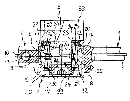
In the view of Fig. 1 a portion of a sickle 1 with the knife back 2 and a
knife blade 3
CA 02719849 2010-11-01
6
attached thereto is visible, wherein in the paper plane in extension of the
knife back
2, a multitude of such knife blades 3 are attached on the knife back 2. At the
end of
the knife back 2 a connection element 4, preferably metallic, in form of a
sickle head
eye is attached, which has a first end face 7 and a second end face 8 and a
through
bore 6, extending through the same between the two end faces 7, 8 and which
through bore 6 is centred on a longitudinal axis 5.
As it is especially visible from Fig. 2, the connection element 4 is formed as
an open.
ring. A gap 9 extends between the two end faces 7, 8. The gap 9 extends
parallel to
the longitudinal axis 5. It could, however, also be arranged with an angle
thereto.
At both sides of the gap 9, two lugs 10, projecting away from the longitudinal
axis 5,
are arranged. One of the two lugs 10 is provided with a through extending bore
12,
which is arranged on an axis 36, which intersects the longitudinal axis 5 at a
dis-
tance. On the axis 36 of this bore 12, a threaded bore 13 is arranged in the
second
lug 10. A tensioning screw 11, especially a head screw, is passed through the
bore
12 and is screwed into the threaded bore 13, so that it effects a reduction of
the
cross-section of the through bore 6, depending on how far it is tightened.
Here, gen-
erally, a through bore can be provided at both sides, through which the
tensioning
screw is passed, wherein this can then be secured with a nut.
An intermediate element 14, preferably metallic, as it is especially visible
from Fig-
ures 3 to 6, rests in the circular cylindrical through bore 6. This
intermediate element
14 has a wall 16, extending circumferentially around the longitudinal axis 5,
and a
bottom 17, closing at one side the intermediate element 14.
The intermediate element 14 is preferably made from steel, and can, in this
case, be
encased with plastic, e.g. insert molded. Generally, also other materials can
be used,
as long as they ensure the required elasticity of the wall portions present
between the
first slots 15. For example also a plastic material can be used. For
increasing the
thermal conductivity, metal particles can, in this case, be embedded in the
plastic.
The wall 16 has a spherical inner face 18 and a circular cylindrical outer
face 19. It is
accommodated with the circular cylindrical outer face 19 in the circular
cylindrical
CA 02719849 2010-11-01
7
through bore 6 of the connection element 4 and is therein displaceable along
the lon-
gitudinal axis 5.
A rotational bearing, formed as rolling member bearing 32, comprises an outer
bear-
ing ring 20, which is closed in circumferential direction and has a spherical
outer face
21. The spherical outer face 21 is adapted to the spherical inner face 18 of
the inter-
mediate element 14. The outer bearing ring 20 is held by this arrangement
pivotably
in the intermediate element 14. The assembly of the intermediate element 14 on
the
outer bearing ring 20 is achieved by means of elastic expansion of the wall 16
of the
intermediate element 14. Thus, the intermediate element 14 can be easily and
se-
curely mounted on the rolling member bearing 32.
The outer bearing ring 20 has two conical outer races 22, which diameter
decreases
towards each other. Furthermore, a two-piece inner bearing ring 23 is
provided, as
they are common in tapered roller bearings. The inner bearing ring 23 has two
inner
races 24. Between the outer races 22 of the outer bearing ring 20 and the
inner races
24 of the inner bearing ring 23, two rows of rolling members 25 in form of
tapered
rollers are arranged in circumferential direction. The inner bearing ring 24
forms an
accommodation bore 26, which is formed circular cylindrical and in which a
driving
trunnion 29 of the head bearing holder 38 of a sickle drive is received
fixedly. The
driving trunnion 29 ends in a shoulder 31. The inner bearing ring 23 abuts via
a pro-
tection ring 26 this shoulder 31. The inner bearing ring 23 is pressed against
this
shoulder 31 by an attachment ring 30, which is retained by a screw 33, which
is
screwed-in along the longitudinal axis 5 into the driving trunnion 29. Thus,
also the
two bearing rows of the rolling member bearing 32, formed as a conical roller
bear-
ing, are pre-tensioned. The rolling member bearing 32 can be made from a
metallic
material, which is acceptable for such bearings and loadings, as they are
common in
sickle drives. It is obvious that generally also other rolling member
bearings, e.g. a
double-row angular contact ball bearing or friction bearings can be used.
The sealing is achieved by the cup-shaped intermediate element 14 with the
bottom
17 and in direction towards the shoulder 31 by a seal 34 and the protection
ring 28. A
lubricant chamber 40, which is delimited by the cup-shaped intermediate
element 14
and by the seal 34, can be provided with lubricant via a lubricant channel 37
in the
CA 02719849 2010-11-01
8
driving trunnion 29 of the head bearing holder 38. At a lubricant channel
inlet 43,
which is accessible from the outside, a lubricating nipple 42 is provided.
For the assembly of the intermediate element 14, the lubricating nipple 42 is
not ini-
tially inserted, so that during the assembly air can escape from the lubricant
chamber
40 through the lubricant channel 37. Only after the assembly, the lubricating
nipple
42 is inserted and the lubricant chamber 40 is filled with lubricant. While
lubricating
the rolling member bearing 32 via the lubricating nipple 42, the lubricant or
air can
escape through a sealing lip 41 of the seal 34 on the rolling member bearing
32.
The edge 27 of the intermediate element 14 becomes especially evident from
Fig. 6.
On the side, facing away from the bottom 17, an opening with a
circumferentially ex-
tending inner assembly face 39, which expands conically in direction to the
edge 27
of the wall 16, facing away from the bottom 17, is provided on the wall 16.The
as-
sembly face 39 facilitates the attachment and the pressing-on of the
intermediate
element 14 onto the outer bearing ring 20 of the rolling member bearing 32 and
sup-
ports the radial expansion of the wall 16 during the assembly on the outer
bearing
ring.
The correct position of the driving trunnion 29 in pivot direction around the
pivot cen-
tre, formed by the spherical inner face 28 and the spherical outer face 20,
and which
is arranged on the longitudinal axis 5, can be fixed corresponding to the
assembly
conditions, i.e. also in an inclined position and a position of the
intermediate element
14, adjusted along the axis of the through bore 6, such, that the tensioning
means in
form of the tensioning screw 11 are tightened. Thus, the cross-section of the
through
bore 6 is reduced such, that a radial force acts on the intermediate element
14. As
the intermediate element 14 itself is radially elastic, the diameter of this
intermediate
element 14 can also be reduced and this presses with its spherical inner face
18
against the spherical outer face 24 of the outer bearing ring 20. Thus, this
is fixed.
3o The outer bearing ring 20 is selected concerning its dimensions such, that
it is does
not deform and, thus, has no effect on the bearing play and the operational
condi-
tions of the rolling member bearing due to the pressing-on.
By forming the intermediate element 14 from a metal and especially from steel,
which
CA 02719849 2010-11-01
9
is so elastic, that it can return to its original shape, in which the slot in
the relaxed
condition has its largest width, the clamping effect is effectively cancelled
after the
loosening of the tensioning screw and a renewed smooth-running adjustment is
pos-
sible.
In Fig. 7, an alternative embodiment of an intermediate element 14 is shown,
which
for increasing the radial elasticity of the intermediate element 14 has slots
15, 35.
The wall 16 has, starting from an edge 27 facing away from the bottom 17, at
least
one, preferably at least three first slots 15. These first slots 15 are
arranged parallel
1o to the longitudinal axis 5 distributed along the circumference of the wall
16, but, how-
ever, can extend with an angle to the longitudinal axis 5.
To increase further the elasticity of the wall 16, two slots 35 are provided
along the
circumference, which are arranged off-set to the first slots 15 such, that
these do not
start from the edge 27. To prevent a leakage of lubricant, the first slots 15
as well as
the second slots 35 end, when seen from the edge 27, within the through bore
6. Al-
ternatively, the slots 15, 35 can also be filled with a rubber material, which
is vulcan-
ized to the intermediate element 14, so that the slots 15, 35 offer the
necessary elas-
ticity and are, at the same time, sealed to the outside.
CA 02719849 2010-11-01
Reference numerals list
1 sickle
2 knife back
5 3 knife blade
4 connection element
5 longitudinal axis
6 through bore
7 first end face
10 8 second end face
9 gap
10 lug
11 tensioning screw
12 bore
13 threaded bore
14 intermediate element
15 first slot
16 wall
17 bottom
18 spherical inner face
19 circular cylindrical outer face
20 outer bearing ring
21 spherical outer face
22 outer race
23 inner bearing ring
24 inner race
25 rolling member
26 accommodation bore
27 edge
28 protection ring
29 driving trunnion
30 attachment ring
31 shoulder
32 rolling member bearing
CA 02719849 2010-11-01
11
33 screw
34 seal
35 second slot
36 axis
37 lubricant channel
38 head bearing holder
39 assembly face
40 lubricant chamber
41 sealing lip
42 lubricating nipple
43 lubricant channel inlet