Note: Descriptions are shown in the official language in which they were submitted.
CA 2720113 2017-03-09
- 1 -
A CONDENSATION MANAGEMENT SYSTEM, A FURNACE INCLUDING THE
SAME AND A CONDENSATION COLLECTION BOX
TECHNICAL FIELD
This application is directed, in general, to furnaces
and, more specifically, to removing condensation from
furnaces.
BACKGROUND
HVAC systems can be used to regulate the environment
within an enclosure.
Typically, an air blower is used to
pull air from the enclosure into the HVAC system through
ducts and push the air back into the enclosure through
additional ducts after conditioning the air (e.g., heating or
cooling the air). For
example, a furnace, such as a gas
furnace may be used to heat the air.
High efficiency gas-fired appliances
including
residential furnaces typically rely on a mechanical means,
such as a combustion air inducer, to create controlled mass
flow thru the flue side of the furnace heat exchanger. As
the heated air flows therethrough, condensation is formed.
To prevent damage to furnace components, such as a pressure
sensing devices, the condensation is collected and removed
from the furnace. This
may be particularly evident with
condensing or high efficiency (>90% AFUE) furnaces where the
removal of condensation generated during the combustion
process is needed.
CA 2720113 2017-03-09
- 2 -
SUMMARY
In one aspect, the disclosure provides a condensation
management system for a furnace. In
one embodiment, the
condensation management system includes: (1) a first drain
hose positioned to drain flue condensation from a flue pipe
of the furnace, (2) a second drain hose positioned to drain
the flue condensation from the flue pipe and (3) a
condensation collector box configured to collect both the
flue condensation and combustion condensation from a heat
exchanger of the furnace, the condensation collector box
including at least one drain for draining both the flue
condensation and the combustion condensation therefrom.
In another aspect, a furnace is disclosed. In
one
embodiment, the furnace includes: (1) a heat exchanger, (2) a
combustion air inducer configured to generate air flow
through the heat exchanger, (3) a flue pipe configured to
vent gas from the furnace and (4) a condensation management
system including: (4A) a first drain hose positioned to drain
flue condensation from the flue pipe, (4B) a second drain
hose positioned to drain the flue condensation and (4C) a
condensation collector box configured to collect both the
flue condensation and combustion condensation from the heat
exchanger, the condensation collector box including at least
one drain for draining both the flue condensation and the
combustion condensation therefrom.
In yet another aspect, a CEHB (cold end header box) is
disclosed. In one embodiment, the CEHB includes: (1) a front
having a fixed orifice configured to regulate gas flow
through a heat
CA 02720113 2010-11-02
P100007CA - 3 -
exchanger of the furnace, the front coupled to first,
second, third and fourth sides that extend from the front
in a first direction, (2) a first drain coupled to the
first side at an opening thereof located proximate the
second side, the first drain extending from the first
side along an axis parallel with the second and third
sides, (3) a second drain coupled to the fourth side at
an opening thereof located proximate the second side, the
second drain extending from the fourth side along the
axis parallel with the second and third sides, (4) a
first drain port coupled to the front proximate the
second side and (5) a second drain port coupled to the
first drain, wherein the first drain port and the second
drain port extend in a second direction that is generally
opposite the first direction.
BRIEF DESCRIPTION
Reference is now made to the following descriptions
taken in conjunction with the accompanying drawings, in
which:
FIG. 1 is an exploded isometric view of a portion of
an embodiment of a furnace constructed according to the
principles of the disclosure;
FIG. 2 is a front isometric view of an embodiment of
a condensation collector box constructed according to the
principles of the disclosure;
FIG. 3 is a rear isometric view of the condensation
collector box of FIG. 2;
FIG. 4 is a functional view of an embodiment of a
condensation collector box constructed according to the
principles of the disclosure showing normal operation
when installed in an upright positioned furnace;
CA 02720113 2010-11-02
P100007CA - 4 -
FIG. 5 is a functional view of the condensation
collector box in FIG. 4 when installed in a horizontal
lefL position; and
FIG. 6 is a functional view of the condensation
collector box in FIG. 4 when installed in a horizontal
right position.
DETAILED DESCRIPTION
To prevent build-up of the condensation and protect
monitoring equipment of the furnace, for example pressure
sensing devices, proper drainage of the condensation is
needed. Conventional
furnaces may require multiple
pressure sensing devices or require relocating the
pressure sensing devices when a furnace is used in
different positions in order to properly sense water
build-up (under blocked drain conditions) and protect the
sensing devices from condensation.
Additionally,
rerouting of hoses used for drainage or for sensing
pressure may also have to be relocated when a furnace is
installed at different positions.
Accordingly, disclosed herein is a condensation
management system that collects condensation from both a
furnace heat exchanger and flue (vent) pipe of the
furnace into a single collection box from which the
condensation can then drain from the furnace. A flow
restriction orifice located at the drain ports of the
collection box that receive the drain hoses from the flue
pipe of the furnace is employed to meter the amount of
flue gas bypass back to the collector box. The disclosed
condensation management system can be used on a single or
multiple position furnace.
Conventional furnace designs may separately drain
condensation generated in the flue (vent) pipe (i.e.,
CA 02720113 2010-11-02
P100007CA - 5 -
flue condensation) and the condensation generated in the
furnace heat exchanger (i.e., combustion condensation).
Separately draining the flue condensation and the
combustion condensation typically requires a larger, dual
pressure chamber condensation trap and multiple safety
pressure switches to shut down the furnace in the event
of an abnormal operating condition. In addition,
having
multiple safety pressure switches also can require that
components be relocated at installation (depending on the
desire unit configuration) increasing the likelihood of
errors.
Advantageously, the disclosed condensation
management system reduces the number of safety pressure
switches that are typically needed. The
collection box
that is disclosed includes a positive pressure channel
and a negative pressure channel that are configured to
allow the measurement of combustion pressure to respond
to abnormal condensate levels.
Additionally, the
disclosed system eliminates the rerouting of condensation
and pressure switch hoses at installation and provides a
negative pressure trap that eliminates or at least
greatly reduces the possibility of flue product leakage
into an enclosed space, such as a home, when a dry (not
primed trap) condition exists. A smaller trap design is
also possible. All of these features of the disclosed
system offer a combination of reduced product cost,
simplified product installation and increased furnace
safety.
Turning now to FIG. 1, illustrated is an exploded
isometric view of a portion of an embodiment of a furnace
100 constructed according to the principles of the
disclosure. The furnace
100 may be a multi-position
furnace. In some
embodiments, the furnace may be a
CA 02720113 2010-11-02
P100007CA - 6 -
residential gas furnace. The furnace 100 includes an
embodiment of a header box that is used for collecting
condensation generated in the furnace 100. The furnace
100 also includes a condensation management system that
includes the header box.
The furnace 100 includes a housing 110 having a
front opening 112 within which a mounting shelf 114 is
located. The mounting
shelf 114 has an opening 116
therein and supports a heat exchanger assembly 120 over
the opening 116. The heat
exchanger assembly 120
includes a primary heat exchanger 122 and a secondary
heat exchanger 126. The primary
heat exchanger 122
includes a row of six heat exchangers (one referenced as
124) coupled to one another. The heat
exchangers are
generally serpentine and have three approximately 1800
folds such that the heat exchangers cross over the
opening 116 four times, terminating in inlets 125 (of the
primary heat exchanger 122) and outlets 127 (of the
secondary heat exchanger 126) that are generally mutually
coplanar and oriented toward the opening 112 of the
housing 110. Alternative
embodiments of the heat
exchanger assembly 120 may have more or fewer heat
exchangers coupled to one another in one or more rows.
Additionally, alternative embodiments may have
alternative heat exchanger configurations.
A burner assembly 140 contains an electronically-
controlled solenoid valve 142, a manifold 144 leading
from the valve 142 and across, the burner assembly 140,
one or more gas orifices (not shown) coupled to the
manifold 144 and one or more burners (not shown)
corresponding to and located proximate the gas orifices.
The illustrated embodiment of the burner assembly 110 has
a row of six burners. Alternative embodiments of the
CA 02720113 2010-11-02
P100007CA - 7 -
burner assembly 140 may have more or fewer burners
arranged in one or more rows. A combustion air inlet 146
allows air in for the burner assembly 140. In an
assembled configuration, the burner assembly 140 is
located proximate the heat exchanger assembly 120 such
that the burners thereof at least approximately align
with the inlets 125.
The furnace 100 also includes a draft inducer
assembly 150 having a combustion air inducer 154 and a
combustion flue collar 156 coupled to an outlet of the
combustion air inducer 154. In an
assembled
configuration, the draft inducer assembly 150 is located
proximate the heat exchanger assembly 120 such that the
combustion flue collar 156 approximately aligns with a
flue pipe 148 that directs undesired gases (e.g., gaseous
products of combustion) away from the furnace 100.
Associated with the draft inducer assembly 150 are first
and second drain hoses, 151, 152, that provide a path to
drain flue condensation from the flue pipe 148 and the
combustion flue collar 156. The combustion flue collar
156 includes first and second drainage export ports that
are not visible in FIG. 1 but are configured to receive
the first and second drain hoses 151, 152, and allow the
flue condensation to flow therethrough. The first
and
second drain hoses 151, 152, may be conventional devices
that are used in furnaces to carry liquids such as water.
A blower 160 is suspended from the shelf 114 such
that an outlet (not referenced) thereof approximately
aligns with the opening 116. An
electronic controller
170 is located proximate the blower 160 and is configured
to control the blower, the valve 142 and the combustion
air inducer 154 to cause the furnace to provide heat. A
CA 02720113 2010-11-02
P100007CA - 8 -
cover 180 may be placed over the front opening 112 of the
housing 110.
A CEHB 190 provides an interface between the
combustion air inducer 154 and the secondary heat
exchanger 126. The combustion
air inducer 154 has an
inlet coupled to the CEHB 190. In an
assembled
configuration, the draft inducer assembly 150 is located
proximate the heat exchanger assembly 120 such that the
CEHB 190 approximately aligns with the outlets 127 and
the combustion flue collar 156 approximately aligns with
the flue pipe 148.
The furnace 100 also includes a pressure sensing
device 195 that is configured to monitor the combustion
pressure through the heat train of the furnace 100. The
pressure sensing device 195 may be mechanical
differential pressure sensing device (such as a pressure
switch) or an electronic sensor which provide feedback to
an integrated electronic controller of the furnace 100,
such as the electronic controller 170. The pressure
sensing device 195 includes inputs for determining the
combustion pressure (which verifies proper flow through
the heat exchanger). The inputs of the pressure sensing
device 195 are coupled to pressure ports of the CEHB 190.
The pressure sensing device 195 may be fastened to the
ports of the CEHB 190 through conventional hoses.
Additionally, the pressure sensing device 195 may be
coupled to the electronic controller 170 or the valve 142
through conventional means. In some
embodiments, the
pressure sensing device 195 may be fastened to the CEHB
190.
In the illustrated embodiment, the controller 170
turns on the combustion air inducer 154 to initiate a
draft in the heat exchangers (including the heat
CA 02720113 2010-11-02
P100007CA - 9 -
exchanger 124) and purge potentially harmful unburned or
combustion gases. Then the
controller 170 opens the
valve 142 to admit gas to the manifold 144 and the one or
more gas orifices, whereupon the gas begins to mix with
air to form a combustible mixture. Then the controller
170 activates an igniter (not shown in FIG. 1) to attempt
to ignite the combustible mixture. If the
output of a
flame rectification circuit indicates that the
combustible mixture has not ignited within a
predetermined period of time, the controller 170 then
closes the valve 142 and waits until attempting to start
again. If the output of the flame rectification circuit
indicates that the combustible mixture has ignited within
the predetermined period of time, the controller 170 then
activates the blower 160, which forces air upward through
the opening 116 and the heat exchanger assembly 120. As
it passes over the surfaces of the heat exchangers, the
air is warmed, whereupon it may be delivered or
distributed as needed to provide heating.
As the undesired products of combustion are
exhausted through the flue pipe 148 via the combustion
flue collar 156, flue condensation forms along the flue
collar 156 and the flue pipe 148.
Additionally, as
heated gases flow through the CEHB 190 from the heat
exchanger 120, combustion condensation gathers in the
CEHB 190. To prevent damage from the condensation, the
furnace 100 includes a condensation management system
that includes the first and second drain hoses 151, 152,
coupled to the CEHB 190. The
condensation management
system collects both the flue condensation and the
combustion condensation at a single collection box, the
CEHB 190, and provides a path to drain the condensation
away from the furnace 100. The
condensation management
CA 02720113 2010-11-02
P100007CA - 10 -
system advantageously employs a positive pressure at the
flue pipe 148, a negative pressure at the CEHB 190 and
the first and second drain hoses 151, 152, to direct the
flue condensation to the CEHB 190. FIG. 2 and
FIG. 3
provide a more detailed look at an embodiment of a
collector box for the condensation management system.
FIGs. 4, 5 and 6 illustrate an embodiment of a combustion
management system, such as one that includes the first
and second drain hoses 151, 152, and the CEHB 190, being
used in different furnace positions.
FIG. 2 is a front isometric view of an embodiment of
a collector box for a condensation management system
constructed according to the principles of the
disclosure. The collector box may be a CEHB such as the
CEHB 190. As such, the illustrated collector box of FIG.
2 will be referred to hereinafter as the CEHB 190 of FIG.
1.
As noted above, the CEHB 190 provides an interface
between the secondary heat exchanger 126 and the
combustion air inducer 154 that draws combustion air
through the heat exchanger 120. As such, the CEHB 190 is
configured to provide an exit for the heated gas from the
heat exchanger via the secondary heat exchanger 126. The
CEHB 190 is also configured to remove the combustion
condensation associated with the heated gas.
Accordingly, the CEHB 190 is typically constructed of a
non-metallic material that is resistive to water
corrosion. The CEHB 790, for example, may be constructed
of a plastic.
The CEHB 190 can be employed in a multi-position gas
furnace such as the furnace 100. Accordingly, the CEHB
190 includes components of a multi-position drain system
that includes a first drain port 210, a second drain port
CA 02720113 2010-11-02
P100007CA - 11 -
212, a left drain 214 and a right drain 216. The first
and second drain ports 210, 212, are positioned and
configured to couple to drain hoses, such as drain hoses
151, 152, from the combustion flue collar 156 and allow
drainage of exhaust condensation into the CEHB 190. The
orifices of the first and second drain ports 210, 212,
that receive drain hoses are configured to meter the
amount of flue gas bypass back to the CEHB 190. The
first and second drain ports 210, 212, therefore are
configured to allow drainage into the CEHB 190 while
reducing flue gas back to the CEHB 190. Depending on the
installation of the furnace 100, the left drain 214, the
right drain 216 or both the left and right drains 214,
216, may be used to remove condensation from the CEHB
190. As illustrated in FIG. 2, the first drain port 210
extends from the first drain 214 and the second drain
port 212 extends from a front face of the CEHB 190.
Located on the four sides of the CEHB 190 is a
flange 220 that is configured to attach the CEHB 190 to
the secondary heat exchanger 126. The flange 220
includes holes, in which hole 222 is denoted, that are
used to mechanically attach the CEHB 190 to the secondary
heat exchanger 126. A gasket is typically used between
the flange 220 and the secondary heat exchanger 126.
The CEHB 190 also includes a support collar 230 that
is used to couple the combustion air inducer 154 to the
CEHB 190. The support collar 230, therefore, corresponds
to an inlet of the combustion air blower 154 for drawing
air through the heat exchanger 120. The support collar
230 is configured to help support the combustion air
inducer 154 in such a way that the inducer 154 requires
only two screws compared to the traditional four screws
needed to mount to the CEHB 190. A gasket
denoted in
CA 02720113 2010-11-02
P100007CA - 12 -
FIG. 2 is typically used with the support collar 230 for
coupling the CEHB 190 to the combustion air blower 154.
Located within the circumference of the support
collar 230 (and therefore within the inlet of the
combustion air blower 154) is a fixed orifice 240. The
fixed orifice 240 is configured to regulate gas flow
through the heat exchanger 120. The fixed
orifice 240
may be sized based on an input size of the furnace 100.
Also located within the circumference of the support
collar 230 are a negative channel supply port 244 and a
positive channel supply port 246. Each of these ports in
the front face of the CEHB 190 provides an opening for
supplying air to the respective channels. The size and
location of the fixed orifice 240, the negative channel
supply port 244, the positive channel supply port 246 and
the size and location of positive and negative pressure
channels 270, 280, (illustrated in FIG. 3) may be
determined through empirical testing to provide a target
pressure or pressure range as detected by a pressure
sensing device for determining combustion pressure. The
advantage of such an arrangement of the CEHB 190 is that
a common pressure switch can be used for various input
sizes of furnaces as well as provide a pressure signal
that is suitable to a gas-air amplified gas valve to
allow input rate modulation.
The CEHB 190 also includes a connection system 235
having alignment protrusions as denoted in FIG. 2 that
are used to couple the pressure sensing device 195 to the
CEHB 190. The
connection system 235 and the
corresponding protrusions may vary depending on the type
or model of the pressure sensing device 195 to be
attached to the CEHB 190.
CA 02720113 2010-11-02
P100007CA - 13 -
The CEHB 190 further includes a positive pressure
port 250 and a negative pressure port 260 that are
coupled to a positive input and a negative input of a
pressure sensing device, such as the pressure sensing
device 195. The pressure sensing device is configured to
monitor a combustion pressure across the fixed orifice
240 based on data received at the negative input port and
the positive input port via the negative and positive
pressure ports 250, 260. The positive
and negative
pressure ports 250, 260, are typically coupled to the
pressure sensing device via pressure sensing device
hoses. The positive pressure port 250 is located within
the positive pressure channel 270 and the negative
pressure port 260 is located within the negative pressure
channel 280 as illustrated in FIG. 3. Locating the
positive pressure port 250 and the negative pressure port
260 within the respective channels and away from openings
of the respective channels protects the pressure ports
and the pressure sensing device from condensation.
The CEHB 190 further includes a screw mounting lug
292 and a water dam 295. The screw mounting lug 292 is
used when mounting a combustion air inducer to the CEHB
190. The water dam 295 is a condensate water dam that is
configured to direct water away from sensitive areas of
the CEHB 190 and assists in maintaining a stable pressure
signal.
FIG. 3 is a rear isometric view of the CEHB 190 that
illustrates the positive pressure channel 270 and the
negative pressure channel 280. Though not
visible in
FIG. 3, the positive pressure channel 270 includes the
positive pressure port 250. During normal operation, the
positive pressure channel 270 has the same or about the
same pressure as within the main cavity of the CEHB 190.
CA 02720113 2010-11-02
P100007CA - 14 -
As such, locating the positive pressure port 250 within
the positive pressure channel 270 allows measuring of the
combustion pressure while protecting the positive
pressure port 250 from condensation. Other components of
the positive pressure channel 270 and the negative
pressure channel 280 that are not visible in FIG. 3 (or
FIG. 2) include the negative channel supply port 244, the
positive channel supply port 246 and an orifice located
within the positive pressure channel 270 that is used to
restrict a flow therethrough. Additionally, the negative
pressure channel 280 includes bleed ports that are not
visible in FIG. 2 or FIG. 3. The bleed
ports are
configured to reduce the pressure received through the
negative channel supply port 244 to within a targeted
range when measured at the negative pressure port 260. A
size, configuration and location of the channels 270,
280, and the various components thereof may be determined
through empirical testing to provide a target pressure or
pressure range when detected by a pressure sensing device
to correlate to a targeted pressure drop or flow thru the
heat exchanger.
A first end of the positive pressure channel 270, an
inlet end 272, extends within the support_ collar 230. A
second end of the positive pressure channel 270, a
pressure reference inlet 274, opens toward the side of
the CEHB 190 having the first and second drains 214, 216.
Furthermore, the open-ended pressure reference inlet 274
is located such that the collection of an undesired level
of condensate within the CEHB 190 will cause the pressure
within the positive pressure channel 270 to change. The
monitoring of this change by the pressure sensing device
195 will allow the furnace to be shut down safely in
response to the change. The positive
pressure channel
CA 02720113 2010-11-02
P100007CA - 15 -
270 has a quadrilateral cross section and includes four
sections joined at or about 90 degrees to form a
continuous open channel from the inlet end 272 to the
pressure reference inlet 274.
Though not visible in FIG. 3, the negative pressure
channel 280 includes the negative pressure port 260. The
negative pressure channel 280 is configured to reduce the
high negative pressure that is present at the inlet of
the combustion air inducer 154 to a targeted pressure or
pressure range at the negative pressure port 260. As
such, locating the negative pressure port 260 within the
negative pressure channel 280 allows measuring of the
combustion pressure signal while protecting the negative
pressure port 260 from condensation. The negative
pressure channel 280 includes a first end denoted as a
closed end 282. A second end
of the negative pressure
channel 280, an open end 284, opens toward the side of
the CEHB 190 having the first and second drains 214, 216.
Furthermore, the open end 284 is located such that the
collection of an undesired level of condensate within the
CEHB 190 will cause the pressure within the negative
pressure channel 280 to change. The
monitoring of this
change by the pressure sensing device 195 will allow the
furnace to be shut down safely in response to the change.
The negative pressure channel 280 has a quadrilateral
cross section and includes four sections that are joined
to form a continuous open channel from the closed end 282
to the open end 284.
Located within a supply section 286 of the negative
pressure channel 280 is the negative channel supply port
244. A portion of
the supply section 286 including the
negative channel supply port 244 is located within the
circumference of the support collar 230 and, therefore,
CA 02720113 2010-11-02
P100007CA - 16 -
the corresponding inlet of the combustion air inducer
154. Sides of the
negative pressure channel 280 around
the open end 284 are shaped to provide a water shroud to
protect the negative pressure port 260 from
contamination.
The CEHB 190 has four sides coupled to a front face
to form an open box. One side of the four sides is the
upflow drainage side 320 that collects condensation and
allows drainage of the condensation when the CEHB 190 is
used in a furnace that is installed in an upflow position
(e.g., see FIG. 4). Both the
first and second drains
214, 216, are positioned proximate the upflow drainage
side 320 of the CEHB 190 to allow drainage of
condensation collected thereat. The first
drain 214 is
coupled to an opening of a horizontal left position side
330 of the CEHB 190 that collects condensation and allows
drainage of the condensation when the CEHB 190 is used in
a furnace that is installed in a horizontal left position
(e.g., see FIG. 5). The second
drain 216 is coupled to
an opening of a horizontal right position side 340 of the
CEHB 190 that collects condensation and allows drainage
of the condensation when the CEHB 190 is used in a
furnace that is installed in a horizontal right position
(e.g., see FIG. 6).
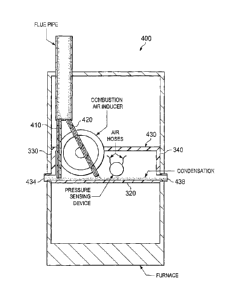
FIG. 4 is a functional view of an embodiment of a
condensation management system 400 constructed according
to the principles of the disclosure. The condensation
management system 400 is shown in the environment of a
furnace in an upflow position. The
condensation
management system 400 includes a first drain hose 410, a
second drain hose 420, and a CEHB 430. Components of the
furnace are also illustrated including a flue pipe, a
CA 02720113 2010-11-02
P100007CA - 17 -
combustion air inducer, a pressure sensing device and
hoses of the pressure sensing device.
The first and second drain hoses 410, 420, provide a
drainage path for flue condensation from the flue pipe to
the CEHB 420. The first and second drain hoses 410, 420,
may be conventional hoses, pipes or conduits that used in
furnaces to carry water. At the flue pipe end, the first
and second drain hoses 410, 420, may be coupled to
drainage export ports located in a collar of the flue
pipe. At the CEHB end, the first and second drain hoses
410, 420, may be coupled to drainage ports of the CEHB
430.
The condensation management system 400 employs a
posit:lye pressure zone in the flue pipe to drive the flue
condensation from the flue pipe, through the first and
second drain hoses 410, 420, and to the CEHB 430 that has
a negative pressure zone compared to the flue pipe. In
the upflow position, both the first and second drain
hoses 410, 420, can be used to drain the flue
condensation. In addition to
collecting the flue
condensation, the CEHB 430 also collects combustion
condensation from the furnace (e.g., the heat exchanger
of the furnace). A first
drain 434 and a second drain
438 of the CEHB 430 may be used to provide a drainage
path from the CEHB 430. In one
embodiment, either the
first drain 434 or the second drain 438 is used for
drainage and the other unused drain is plugged. The
drainage export ports, the drain ports and the drains
discussed with respect to FIG. 4 may be configured and
constructed as the above described drainage export ports,
drain ports and drains in FIGs. 1-3.
As illustrated in FIG. 5 and 6, the condensation
management system 400 advantageously provides
CA 02720113 2010-11-02
P100007CA - 18 -
condensation drainage in multiple furnace positions
without requiring the rerouting of drain hoses or
pressure sensing device hoses. In FIG. 5,
the
condensation management sysLem 400 is used in a furnace
installed at a horizontal left position. In the
horizontal left position, the first drain hose 410
provides a single drainage path from the flue pipe to the
CEHB 430. In this installation, the second drain 438 can
be plugged.
In FIG. 6, the condensation management system 400 is
used in a furnace installed at a horizontal right
position. In Lhe horizontal right position, the second
drain hose 420 provides a single drainage path from the
flue pipe to the CEHB 430. In this
installation, the
first drain 434 can be plugged.
Those skilled in the art to which this application
relates will appreciate that other and further additions,
deletions, substitutions and modifications may be made to
the described embodiments.