Note: Descriptions are shown in the official language in which they were submitted.
CA 02720432 2010-10-01
WO 2009/122369 PCT/IB2009/051379
DROP CONTROLLING AND COUNTING - VALVE ON KEY
FIELD OF THE INVENTION
The present invention relates to means and a method designated to prevent
medical errors when injecting IV fluids and medications into humans and
animals,
and, in particular to ensure authentication of medications infused in IV bags.
BACKGROUND OF THE INVENTION
An apparatus, system and method for administration of a substance is described
in the International Application PCT/IL/2005/001118 of Sharvit et al.,
International
Publication Number WO 2006/046242, which is incorporated by reference for all
purposes as if fully set forth herein.
WO 2006/046242 discloses an infusion control valve adapted to be actuated by a
valve actuator, an infusion valve actuator adapted to actuate an infusion
control valve
upon being triggered by an authentication unit and a method for the
administration of
a substance.
The method according to WO 2006/046242 also uses a hand-held (HHD)
computer and a smart (electronic) key.
Means and a method of prevention of error and ensuring authentication of
medications infused in IV bags and syringes, and other authentication, such as
the
verification of movement of fluids in all directions from bags to vials, bags
to
syringes, and syringes to vials, is described in the U.S. provisional patent
application
No. 61/006,578 of Sharvit et al., which is incorporated by reference for all
purposes as
if fully set forth herein.
1
CA 02720432 2010-10-01
WO 2009/122369 PCT/IB2009/051379
U.S. 61/006,578 discloses a drug port valve which has two working modes, a
closed mode which completely prevents the passage of fluid, and an open mode
which
requires authentication and which enables the passage of fluid.
There is a need for a means and a method designated to prevent medical errors
when injecting IV fluids and medications into humans and animals, and, in
particular
to ensure authentication of medications infused in IV bags, which enable
controlling
and monitoring the output of IV fluid passing through such a valve.
SUMMARY OF THE INVENTION
The present invention relates to system, means and a method of use, designated
to prevent medical errors when injecting IV fluids and medications into humans
and
animals, and, in particular to ensure authentication of medications infused in
IV bags,
which enable control and monitoring the output of IV fluid.
The flow through the means is at a dripping rate, as is common in fluid IV's,
and the system, according to the present invention, enables closed circuit
monitoring
of the output, namely the dripping rate, while the mass of the drops is known
and
enables selection of desired output parameters, such as the number of drops
per time
unit and the beginning and end times of the flow, all under the condition of
authentication.
These system, means and method are according to the present invention, some
of whose inventors are also inventors of WO 2006/046242, and U.S. 61/006,578
and
are designated to add further performance to the family of system, means, and
method
of the prior invention.
According to some embodiments of the present invention there is provided a
drop controlling and counting valve on key system for ensuring authentication
and for
2
CA 02720432 2010-10-01
WO 2009/122369 PCT/IB2009/051379
controlling the rate of flow of medications, in liquid state drops, under
control of an
authentication unit, the authentication unit containing characteristics of the
medication
fluid and details of the patient, for calculating a correlation value between
the details
and the characteristics, the drop controlling and counting valve on key system
including: (A) a smart valve including: (i) an immovable assembly including:
(a) a
smart valve to control unit connector; and (B) a control unit including: (i) a
control
unit to smart valve connector, wherein the smart valve to control unit
connector and
the control unit to smart valve connector are compatible; and (ii) a control
unit
wireless communication subsystem.
According to still further features in the described embodiments the drop
control
and controlling valve on key system further includes: (C) a hand-held computer
including: (i) a hand-held computer wireless communication subsystem, wherein
the
control unit wireless communication subsystem and the hand-held computer
wireless
communication subsystem are compatible.
According to still further features in the described embodiments the immovable
assembly further includes: (b) a lock pin, having no movement capability
relative to
the immovable assembly; (c) a dripping chamber positioned at a lower section
of the
immovable assembly at times of a normal operation; (d) a lower connector
attached to
the dripping chamber; (e) a transmitter light guide disposed between the
dripping
chamber and the smart valve to control unit connector; and (f) a receiver
light guide
disposed between the dripping chamber and the smart valve to control unit
connector.
According to still further features in the described embodiments the smart
valve
further includes: (ii) a moveable assembly, wherein the moveable assembly has
a
limited movement capability within the immovable assembly, and wherein the
3
CA 02720432 2010-10-01
WO 2009/122369 PCT/IB2009/051379
immovable assembly includes: (a) a spike having a shape and dimensions
suitable for
insertion in an IV bag first port.
According to still further features in the described embodiments the smart
valve
further includes: (iii) an internal tubule disposed between the spike and the
lower
connector.
According to still further features in the described embodiments the moveable
assembly further includes (b) a lock having angular movement capability,
wherein the
lock does not block flow of fluid within the internal tubule during times of
storage; (c)
a lock hook for locking the lock in a position pressing on the internal
tubule; and (d) a
drop controller means for controlling the rate of fluid dripping through the
internal
tubule.
According to still further features in the described embodiments the control
unit
further includes: (iii) an optical transmitter, wherein when the control unit
is engaged
to the smart valve, the optical transmitter is positioned opposite the
transmitter light
guide; (iv) an optical receiver, wherein when the control unit is engaged to
the smart
valve, the optical transmitter is positioned opposite the receiver light
guide; and a
control unit locker having angular movement capability, and wherein when the
control unit is connected to the smart valve, the control unit locker can
prevent
disengagement of the control unit from the smart valve.
According to still further features in the described embodiments the control
unit
further includes: (vi) a locking shaft having rotational movement capability;
(vii) a
combining ligule disposed as part of the locking shaft, wherein the combining
ligule
has a shape and dimensions suitable for engagement with the drop controller
means;
and (viii) a cam disposed as part of the locking shaft, wherein the cam has a
shape and
4
CA 02720432 2010-10-01
WO 2009/122369 PCT/IB2009/051379
dimensions suitable for moving the control unit lock in order to enable
disengagement
of the control unit from the smart valve.
According to still further features in the described embodiments the control
unit
further includes: (ix) a step motor, the step motor having a step motor shaft;
(x) a first
cogwheel disposed at the step motor shaft; and (xi) a second cogwheel disposed
at
the locking shaft, wherein the first cogwheel and the second cogwheel
constitute a
control transmission.
According to still further features in the described embodiments the control
unit
further includes: (xii) a microcontroller capable of operating the step motor;
and (xiii)
a power source, for supplying power to the step motor and to the micro-
computer.
According to still further features in the described embodiments the control
unit
further includes: (iii) an optical transmitter, wherein when the control unit
is engaged
to the smart valve, the optical transmitter is positioned opposite the
transmitter light
guide; (iv) an optical receiver, wherein when the control unit is engaged to
the smart
valve, the optical transmitter is positioned opposite the receiver light
guide; a control
unit lock having angular movement capability, and wherein when the control
unit is
connected to the smart valve, the control unit lock can prevent disengagement
of the
control unit from the smart valve; (vi) a locking shaft having rotational
movement
capability; (vii) a combining ligule disposed as part of the locking shaft,
wherein the
combining ligule has a shape and dimensions suitable for engagement with the
drop
controller means; (viii) a cam disposed as part of the locking shaft, wherein
the cam
has a shape and dimensions suitable for moving the control unit lock in order
to
enable disengagement of the control unit from the smart valve; (ix) a step
motor, the
step motor having a step motor shaft; (x) a first cogwheel disposed at the
step motor
shaft; (xi) a second cogwheel disposed at the locking shaft, wherein the first
cogwheel
5
CA 02720432 2010-10-01
WO 2009/122369 PCT/IB2009/051379
and the second cogwheel constitute a control transmission; (xii) a
microcontroller
capable of operating the step motor; and (xiii) a power source, for supplying
power to
the step motor and to the micro-computer.
According to some embodiments of the present invention there is provided a
method for controlling the rate of flow of medications, in liquid state drops,
infused in
IV bags, the method including the stages of. (A) providing a drop controlling
and
counting valve on key system, the drop controlling and counting valve on key
system
including: (i) a first smart valve having a spike; (ii) a control unit; and
(iii) a hand-
held computer; (B) inserting the spike in an IV bag port, wherein the
insertion causes
a state of prevention of fluid flow from the IV bag through the first smart
valve; (C)
connecting the control unit to the first smart valve; (D) scanning a vial
barcode sticker
and a wristband patient barcode by the hand-held computer, and assessing an
authentication; (E) opening a pass which enables flow of fluid through the
first smart
valve; and (F) measuring the flow rate of fluid, by counting fluid drops
passing
through the first smart valve, over a given period of time, wherein the
average mass of
a drop is known.
According to still further features in the described embodiments the method
for
ensuring authentication and for controlling the rate of flow of medications,
in liquid
state drops, infused in IV bags further including the stages of. (G)
calculating an
amount of fluid mass passing through the first smart valve; and (H) preventing
flow of
fluid through the first smart valve, after finding that a fluid mass of a
predetermined
amount passed through the first smart valve.
According to still further features in the described embodiments the method
for
ensuring authentication and for controlling the rate of flow of medications,
in liquid
state drops, infused in IV bags further including the stages of. (I)
disconnecting the
6
CA 02720432 2010-10-01
WO 2009/122369 PCT/IB2009/051379
control unit from the first smart valve; and (J) extracting the spike from the
IV bag
port.
According to still further features in the described embodiments the method
for
ensuring authentication and for controlling the rate of flow of medications,
in liquid
state drops, infused in IV bags further including the stages of. (K)
destroying the first
smart valve.
According to still further features in the described embodiments the method
for
ensuring authentication and for controlling the rate of flow of medications,
in liquid
state drops, infused in IV bags further including the stages of. (L) inserting
a spike of
a second smart valve in an IV bag port, wherein the insertion causes a state
of
prevention of fluid flow from the IV bag through the second smart valve; and
(M)
connecting the control unit to the second smart valve.
Additional objects and advantages of the invention will be set forth in part
in the
description which follows and, in part, will be obvious from the description,
or may
be learned by practice of the invention.
BRIEF DESCRIPTION OF THE DRAWINGS
The invention is herein described, by way of example only, with reference to
the
accompanying drawings, wherein:
Figure 1 is a schematic perspective view illustration of an exemplary
embodiment of the three main assemblies of a drop controlling and counting
valve on
key system, according to the present invention.
Figure 2 is a schematic perspective view illustration of an exemplary
embodiment of an open control unit, without part of the external casing and
additional
parts, according to the present invention.
7
CA 02720432 2010-10-01
WO 2009/122369 PCT/IB2009/051379
Figure 3 is a schematic perspective view illustration of an exemplary
embodiment of an open smart valve, according to the present invention.
Figure 4 is a schematic front view illustration of an exemplary embodiment of
the smart valve, according to the present invention, upon which the section
plane a-a
is marked.
Figure 5 is a cross sectional view a-a schematic illustration of an exemplary,
illustrative embodiment of the smart valve, prior to activation according to
the present
invention.
Figure 6 is a schematic side view illustration of an exemplary embodiment of
the
control unit, according to the present invention.
Figure 7 is a schematic perspective view illustration of an exemplary
embodiment of a smart valve, according to the present invention, connected to
infusion tubule about to be connected to IV bag, according to the present
invention.
Figure 8 is a schematic side view illustration of an exemplary embodiment of a
smart valve, showing its components in a state in which flow is impossible,
according
to the present invention.
Figure 9 is a schematic side view illustration of an exemplary embodiment of a
smart valve, showing the state of its components after locking, according to
the
present invention.
Figure 10 is a schematic side view illustration of an exemplary embodiment of
a
smart valve, which is connected to IV bag prior to connection to a control
unit,
according to the present invention.
Figure 11 is a schematic side view illustration of an exemplary embodiment of
a
smart valve, which is connected to a control unit, according to the present
invention.
8
CA 02720432 2010-10-01
WO 2009/122369 PCT/IB2009/051379
Figure 12 is a schematic side view illustration of an exemplary embodiment of
a
smart valve, which is connected to a control unit, according to the present
invention.
Figure 13 is a schematic perspective view illustration of an exemplary
embodiment of a smart valve, integrated with a control unit and connected
between an
IV bag and an infusion tubule, according to the present invention.
Figure 14 is a schematic perspective view illustration of an exemplary
embodiment of a smart valve, integrated with a control unit and connected
between an
IV bag and an infusion tubule, according to the present invention.
Figure 15 is a schematic perspective view illustration of an exemplary
embodiment of a smart valve, integrated with a control unit and connected
between an
IV bag and an infusion tubule, according to the present invention.
Figure 16 is a schematic side view illustration of an exemplary embodiment of
a
smart valve, which is connected to a control unit, according to the present
invention.
Figure 17 is a schematic perspective view illustration of an exemplary
embodiment of a smart valve, integrated with a control unit and connected
between an
IV bag and an infusion tubule, according to the present invention, during
adjustment
of the control unit.
Figure 18 is a schematic side view illustration of an exemplary embodiment of
a
smart valve, connected to a control unit, according to the present invention.
Figure 19 is a schematic side view illustration of an exemplary embodiment of
a
smart valve, connected to a control unit, according to the present invention.
Figure 20 is a schematic side view illustration of an exemplary embodiment of
a
smart valve, connected between an IV bag and an infusion tubule, according to
the
present invention, in the stage following disconnection from the control unit.
9
CA 02720432 2010-10-01
WO 2009/122369 PCT/IB2009/051379
DETAILED DESCRIPTION OF EMBODIMENTS
The present invention is of drop controlling and counting valve on key system,
means and a method of use, designated to prevent medical errors when injecting
IV
fluids and medications into humans and animals, and, in particular to ensure
authentication of medications infused in IV bags, which enable control and
monitoring the output of IV fluid.
The flow, which is in the form of dripping, is through a valve and is
controlled
by a closed loop controlling sub-system, which can also provide a secure
constant rate
(according the physician protocol setup), namely, other than mass control it
can also
control a constant rate. An additional feature of the controlling sub-system
is the
ability for real-time reporting of every situation to the HHD by means of
wireless
communication, so that the HHD is updated from all units constantly during the
procedure. The control can also include control of the time of beginning and
end of
dripping.
Even though in the embodiments described in the present patent application,
the
drop controlling and counting valve on key system includes one smart valve,
one
control unit, and one hand-held computer, there may be other embodiments in
which
one hand-held computer has wireless communication with more than one control
unit.
The principles and operation of a drop controlling and counting valve on key
system 1000 according to the present invention may be better understood with
reference to the drawings and the accompanying description.
Before explaining at least one embodiment of the invention in detail, it is to
be
understood that the invention is not limited in its application to the details
of
construction and the arrangement of the components set forth in the following
description or illustrated in the drawings.
CA 02720432 2010-10-01
WO 2009/122369 PCT/IB2009/051379
Unless otherwise defined, all technical and scientific terms used herein have
the
same meaning as commonly understood by one of ordinary skill in the art to
which
this invention belongs. The materials, dimensions, methods, and examples
provided
herein are illustrative only and are not intended to be limiting.
The following list is a legend of the numbering of the application
illustrations:
infusion bag barcode sticker
17 IV bag
18 IV bag first port
19 IV bag second port
10 20 infusion tubule
21 patient barcode
30 fluid drops
40 IR radiation
41 wireless communication
100 smart valve
101 patient barcode
102 vial barcode sticker
103 dripping chamber
104 smart valve to infusion tubule connector
105 spike
106 smart valve to control unit connector
107 moveable assembly
108 immovable assembly
109 drop controller means
110 transmitter light guide
11
CA 02720432 2010-10-01
WO 2009/122369 PCT/IB2009/051379
111 receiver light guide
112 internal tubule
113 lower connector
114 lock hook
115 lock
116 lock pin
117 pressure zone
118 drop controller means plane
119 locking wall
120 transmitted light ray
121 reflected light ray
122 integral screw
200 control unit
201 external casing
202 display
203 keyboard
204 control unit to smart valve connector
205 switch
206 step motor
207 control transmission
208 microcontroller
209 power source
210 optical transmitter
211 optical receiver
212 control unit lock
12
CA 02720432 2010-10-01
WO 2009/122369 PCT/IB2009/051379
213 first cogwheel
214 second cogwheel
215 step motor shaft
216 locking shaft
217 spring
218 cam
219 combining ligule
220 control unit wireless communication subsystem
300 hand-held computer
301 LCD screen
302 keypad
303 IR radiation
304 hand-held computer wireless communication subsystem
1000 drop controlling and counting valve on key system
Referring now to the drawings, Figure 1 is a schematic perspective view
illustration of an exemplary embodiment of the three main assemblies of a drop
controlling and counting valve on key system 1000, according to the present
invention. The three main assemblies are: a smart valve 100 designated for one-
time
use, a control unit 200 designated for repeated use, and a hand-held (HHD)
computer
300 which is also for repeated use.
The control unit 200 is suitable for connection to the smart valve 100 and for
its
activation. The hand-held (HHD) computer 300 enables the activation of the
control
unit 200 through wireless communication, following the connection and
calibration of
the control unit 200 and receiving a suitable authentication result from
examination of
the vial barcode sticker and the wristband patient barcode (21).
13
CA 02720432 2010-10-01
WO 2009/122369 PCT/IB2009/051379
The smart valve 100 has spike 105 assembled to its upper part, and dripping
chamber 103 assembled to its lower part. Dripping chamber 103 is a transparent
cylinder which serves as a container for formation of the drops, and its lower
end has
a smart valve to infusion tubule connector 104.
The smart valve 100 also includes a smart valve to infusion tubule connector
104.
The control unit 200 also includes external casing 201 which is composed of a
suitable material, such as plastic for example, and is integrated with a
display 202 for
displaying work data, as well as a keyboard 203 for entering data and a switch
205,
which is a slider with two modes, connection and disconnection of the control
unit
200 to and from the smart valve 100 by means of control unit to smart valve
connector 204.
Figure 2 is a schematic perspective view illustration of an exemplary
embodiment of an open control unit 200, without part of the external casing
201 and
additional parts, according to the present invention.
A motor, which can also be an electric step motor 206, fed from a power source
209, which can also be a chargeable electric battery, drives control
transmission 207,
which includes a first cogwheel 213 and a second cogwheel 214, and which
controls
(monitors) the dripping rate of the fluid drops flowing through the smart
valve (100).
The control unit 200 also includes an optical transmitter 210, optical
receiver
211, and microcontroller 208.
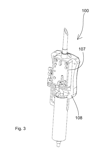
Figure 3 is a schematic perspective view illustration of an exemplary
embodiment of an open smart valve 100, according to the present invention.
14
CA 02720432 2010-10-01
WO 2009/122369 PCT/IB2009/051379
The smart valve 100 includes two assemblies, an immovable assembly 108, and
a moveable assembly 107, which moves when activated within the immovable
assembly 108.
The terms moveable and immovable are used in reference to relative movement
of these assemblies with regard to each other, and are in no way limiting
their
movement with regard to the external environment.
Figure 4 is a schematic front view illustration of an exemplary embodiment of
the smart valve 100, according to the present invention, upon which the
section plane
a-a is marked. The smart valve to control unit connector 106 also includes a
drop
controller 109, and two light guides, the transmitter light guide 110, and the
receiver
light guide 111.
Figure 5 is a cross sectional view a-a schematic illustration of an exemplary,
illustrative embodiment of the smart valve 100, prior to activation according
to the
present invention.
An internal tubule 112 goes through the moveable assembly 107 and is
connected to lower connector 113. Drops can pass through the internal tubule
112
when there is flow of fluid into the dripping chamber 103. In this state, the
lock hook
114 is in open mode when the lock 115 is in its lower position: likewise the
lock pin
116, activates the lock by moving the movable assembly 107, movable assembly
107
is in the upper position.
The illustration shows the two light guides, the transmitter light guide 110,
and
the receiver light guide 111, serving for conduction of the light from the
optical
transmitter 210, and to the optical receiver 211 through the dripping chamber
103. In
this state, the drop controller means 109 is in a fully closed mode.
CA 02720432 2010-10-01
WO 2009/122369 PCT/IB2009/051379
There is still no flow through the internal tubule 112 because there has been
no
connection to any container of fluid.
Figure 6 is a schematic side view illustration of an exemplary embodiment of
the control unit 200, according to the present invention.
The control unit 200 is activated by microcontroller 208 which is electrically
connected to step motor 206, which activates the control transmission 207.
Step motor 206 has a step motor shaft 215, upon which a first cogwheel 213 is
assembled and engaged with a second cogwheel 214, which is assembled to the
locking shaft 216.
The locking shaft 216 is regularly engaged by spring 217.
The locking shaft 216 also includes a cam 218 serving to open the control unit
lock 212. At the end of the locking shaft 216 is combining ligule 219, which
is
designated for controlling the dripping rate by opening and closing the drop
controller
means (109) which is disposed within smart valve (100).
The optical transmitter 210 also includes a light source such as LED, and the
optical receiver 2llalso includes a light-sensitive sensor.
Figure 7 is a schematic perspective view illustration of an exemplary
embodiment of a smart valve 100, according to the present invention, connected
to
infusion tubule 20 about to be connected to IV bag 17, according to the
present
invention. The connection is done by inserting spike 105 into the IV bag 17
through
the IV bag first port 18.
The illustration also shows a control unit wireless communication subsystem
220
which can be a little chip on a board of the microcontroller 208, and whose
role will
be explained in the description of Figure 15.
16
CA 02720432 2010-10-01
WO 2009/122369 PCT/IB2009/051379
Figure 8 is a schematic side view illustration of an exemplary embodiment of a
smart valve 100, showing its components in a state in which flow is
impossible,
according to the present invention. The connection of the smart valve 100 to
the IV
bag 17, as described for the previous illustration, creates movement in the
direction of
the arrow up as shown in the illustration, which indicates movement of the
moveable
assembly 107 relative to the immovable assembly 108, and therefore the lock
pin 116,
which is part of the immovable assembly 108, in motion pushes the lock 115
towards
the lock hook 114. The lock hook 114 enables lock 115 to pass it, but does not
enable
its return. In this state, the internal tubule 112 is completely pressed in
pressure zone
117 so that no fluid can flow through pressure zone 117.
The drop controller means plane 118, which is at the end of the drop
controller
means 109, is fully closed. Namely, as shown in this illustration, the smart
valve 100
is closed, and there is no dripping or continuous flow through the internal
tubule 112.
The need for two modes of the lock hook 114 is a result of the requirement
that during prolonged storage no force will be applied to the internal tubule
112, so
that it is not damaged.
Figure 9 is a schematic side view illustration of an exemplary embodiment of a
smart valve 100, showing the state of its components after locking, according
to the
present invention. While the moveable assembly 107 remains attached to the IV
bag
first port 18 when the immovable assembly 108 moves back to its original
position,
down, as shown by the arrow in the illustration, the lock 115 remains closed,
the lock
pin 116 also returns to its original state, as shown in the illustration, and
the drop
controller means plane 118 also remains closed.
Figure 10 is a schematic side view illustration of an exemplary embodiment of
a
smart valve 100 which is connected to IV bag 17 prior to connection to a
control unit
17
CA 02720432 2010-10-01
WO 2009/122369 PCT/IB2009/051379
200, according to the present invention. The connection of the control unit
200 to the
smart valve 100, is by engaging the control unit to smart valve connector 204
with the
smart valve to control unit connector 106 when moving the control unit 200
right, as
shown by the arrow in the illustration.
Figure 11 is a schematic side view illustration of an exemplary embodiment of
a smart valve 100, which is connected to a control unit 200, according to the
present
invention. The present illustration shows the state of the components of the
smart
valve 100 and the control unit 200, shown only in part, in the first stage of
their
connection process, while the control unit 200 moves right, as shown by the
arrow in
the illustration.
In this first stage the control unit lock 212 slides towards the locking wall
119
and the locking shaft 216 is in a state of "spring wound" toward the drop
controller
means 109.
The optical transmitter 210 is facing the transmitter light guide 110, and the
optical receiver 211 is facing the receiver light guide 111.
The smart valve 100 is in closed mode, which prevents dripping or continuous
flow through the internal tubule 112, by means of the lock 115.
Figure 12 is a schematic side view illustration of an exemplary embodiment of
a smart valve 100, which is connected to a control unit 200, according to the
present
invention. This illustration shows the state of the components of the smart
valve 100
and the control unit 200, which is shown in part, in the second stage of their
connection process.
In this second stage, the control unit 200, with further movement to the
right,
in the direction of the arrow shown in the illustration, is locked to the
smart valve 100.
The control unit lock 212 goes through the locking wall 119 and is locked onto
it. The
18
CA 02720432 2010-10-01
WO 2009/122369 PCT/IB2009/051379
locking motion of the lock 212 is an angular movement which can be generated
by a
spring, not shown in the illustration: while in this case, the lock 212 has
freedom of
angular movement around an axis near its left end, or by means of elasticity
of the
locking wall 119. In this case, it is harnessed at its left end, or with any
other suitable
device.
At this point, the engagement of the locking shaft 216 with the drop
controller
means 109 starts, similar to the engagement of a screwdriver with the head of
a screw,
while the locking shaft 216 is rotated by the step motor 206 and pressed to
the right
for the purpose of engagement by the spring 217 for no more than one full
revolution
until the engagement is complete. At the end of this second stage, passage of
fluid
through the internal tubule 112 is not possible.
Figure 13 is a schematic perspective view illustration of an exemplary
embodiment of a smart valve 100, integrated with control unit 200 and
connected
between an IV bag 17 and the infusion tubule 20, according to the present
invention.
The hand-held computer 300 scans the infusion bag barcode sticker 10, by means
of IR radiation 40, or by means of any other suitable radiation such as RFID,
and
compares the code entered into hand-held computer 300 and the scanned code,
which
is entered into its memory.
Figure 14 is a schematic perspective view illustration of an exemplary
embodiment of a smart valve 100, integrated with control unit 200 and
connected
between an IV bag 17 and the infusion tubule 20, according to the present
invention.
The hand-held computer 300 scans the wristband patient barcode 21 by means
of IR radiation 40, or any other suitable radiation such as RFID, and compares
the
code entered into it with the wristband patient barcode 21 which is scanned
and
entered into its memory.
19
CA 02720432 2010-10-01
WO 2009/122369 PCT/IB2009/051379
Figure 15 is a schematic perspective view illustration of an exemplary
embodiment of a smart valve 100, integrated with the control unit 200 and
connected
between an IV bag 17 and the infusion tubule 20, according to the present
invention.
After scanning the infusion bag barcode sticker 10 and the wristband patient
barcode 21, duplex wireless communication 41 is established between the hand-
held
computer 300, and the control unit 200. If all of the data is authenticated,
the hand-
held computer 300 enables control unit 200 to continue as activated.
The duplex wireless communication 41 is maintained by a control unit wireless
communication subsystem 220 and a hand-held computer wireless communication
subsystem 304 which can be a little chip on a board of the hand-held computer
300.
The hand-held computer 300 is capable of transmitting all of the data, such as
time, dosage, and quantity data, through the wireless communication 41.
During its entire process, the control unit 200 transmits data regarding the
dripping rate and quantity at any given time. When the required dose is given,
or
according to any other criterion, the control unit 200 sends an end message to
hand-
held computer 300 and all of the data is registered in real time.
Figure 16 is a schematic side view illustration of an exemplary embodiment of
a smart valve 100, which is connected to a control unit 200, according to the
present
invention. This illustration shows the state of the components of the smart
valve 100
and the control unit 200, shown only in part, at a stage in which they cannot
be
disconnected from each other, and a process of dripping sensing is started.
The optical transmitter 210 transmits its transmission signals as an AC light
wave in order to prevent background light interference. The light waves pass
through
the transmitter light guide 110 and because there is no dripping, the amount
of light
CA 02720432 2010-10-01
WO 2009/122369 PCT/IB2009/051379
that returns to the receiver light guide 111 is minimal and does not exceed
the
threshold necessary for recognizing a proper signal level.
The transmitted light ray 120 hits the wall of the dripping chamber 103.
The transmitted light ray 120 hits the wall at angle a relative to the
perpendicular
to the wall and is reflected, as a reflected light ray 121, at angle a, with
the
perpendicular serving as a symmetry line, all practically on the same plane.
Note: the light ray may be reflected from the wall, however the reflection is
minimal due to the acute angle.
The reflected light ray 121 in the above described situation is not directed
such
that it can enter the receiver light guide 111, and thus provides a signal,
which is
minimally under threshold, for reception by the optical receiver 211.
Figure 17 is a schematic perspective view illustration of an exemplary
embodiment of a smart valve 100, integrated with a control unit 200 and
connected
between an IV bag 17 and the infusion tubule 20, according to the present
invention,
during adjustment of the control unit 200. The adjustment is achieved by
entering data
into keyboard 203 and receiving results on display 202. After the control unit
200
activates the smart valve 100, the flow of fluid is enabled, and fluid drops
30 begin to
appear in dripping chamber 103.
Figure 18 is a schematic side view illustration of an exemplary embodiment of
a
smart valve 100, connected to a control unit 200, according to the present
invention.
The present illustration shows the state of the components of the smart valve
100
and the control unit 200, shown only in part, at the stage in which the
control unit 200
recognizes drops. The recognition of drops occurs when the course of the
light, as
described in Figure 16, changes when a fluid drop 30, which goes through the
transmitted light ray 120, is disposed in a suitable geometrical location. The
fluid drop
21
CA 02720432 2010-10-01
WO 2009/122369 PCT/IB2009/051379
30 reflects the light such that the reflected light ray 121 enters the
receiver light guide
111, and is received through it in the optical receiver 211. The
microcontroller 208
calculates the elapsed time between two consecutive fluid drops 30 and
activates the
step motor 206 for the purpose of opening or closing, if required, according
to the data
entered in the keyboard.
The microcontroller 208 uses closed loop control, and during the entire time
of
activation monitors the state of the step motor 206, which controls movement
to the
left and right (relative to the illustration plane) of the drop controller
means plane 118.
This is achieved also by means of rotating the integral screw 122, which is an
integral part of the locking axis 216. Closing the integral screw 122 will
reduce the
flow rate, which as noted is a dripping rate, while opening it will increase
the rate.
Figure 19 is a schematic side view illustration of an exemplary embodiment of
a
smart valve 100, connected to a control unit 200, according to the present
invention.
The present illustration shows the state of the components of the smart valve
100 and
the control unit 200, shown only in part, at the stage in which the control
unit 200 is
constantly monitoring the dripping rate. As soon as the dripping stops, for
any reason,
for longer than a given time, such as 30 seconds, the control unit 200 closes
the smart
valve 100 hermetically, and the display 202 displays a message such as "The
system
can be disconnected". Disconnection is performed by pulling switch 205 to the
left, as
shown by the arrow in the illustration, causing the step motor 206 to start
rotating to
opening position, the cam 218 is in the upper position in the end of the
switch 205
position. The step motor 206 rotates by 180 degrees and the cam 218 pushes the
control unit lock 212 down. The position of the switch 205 is monitored by
cutoff
detectors, not shown in the illustration, causing the release of the locking
shaft 216
from the drop controller means 109 and the automatic activation of the step
motor 206
22
CA 02720432 2010-10-01
WO 2009/122369 PCT/IB2009/051379
to open state of the control unit lock 212. Opening the control unit lock 212
is
performed by pressing cam 218, which is connected to locking shaft 216,
towards the
locking wall 119, enabling the disconnection of the control unit lock 212 from
the
smart valve 100, causing the release of locking shaft 216 from the drop
controller
means 109.
Figure 20 is a schematic side view illustration of an exemplary embodiment of
a
smart valve 100, connected between an IV bag 17 and the infusion tubule 20,
according to the present invention, in the stage following disconnection from
the
control unit 200.
The control unit 200 is in closed mode, the drop controller means plane 118,
and
the control unit lock 212 is in open mode and enables further activation (with
another
smart valve 100).
While the invention has been described with respect to a limited number of
embodiments, it will be appreciated that many variations, modifications and
other
applications of the invention may be made, such as designing drop controlling
and
counting valve on key system 1000 in various configurations, for example in
order to
obtain the desired position of the center of gravity by changing the positions
of
various components and even adding balancing weights.
23