Note: Descriptions are shown in the official language in which they were submitted.
CA 02720434 2010-10-06
- 1 -
MAGNETIC ESCUTCHEON MOUNTING ASSEMBLY
Background and Summary of the Invention
100011 The present invention relates to a wall mounted escutcheons. More
specifically,
this invention relates to mounting assemblies for coupling escutcheons coupled
to wall supported
mounting bases.
[0002] Conventional shower valves and escutcheons are known. Escutcheons
typically
hide components of the valve mounting and provide an aesthetic cover for the
shower valve
assembly. More particularly, escutcheons typically are coupled to the valve
assembly with
traditional fasteners, such as screws. Such screws may complicate the
installation process and
are often visible to the shower user, thereby decreasing the aesthetic appeal
of conventional
escutcheon mounting assemblies.
[0003] In one illustrative embodiment of the present disclosure, an
escutcheon mounting
assembly for a valve includes a base configured to be supported by a vertical
wall, and an
escutcheon configured to be coupled to the base, the escutcheon including an
opening for
receiving a valve user interface. A magnetically attractive element is
supported by one of the
base and the escutcheon, and at least one magnet is affixed to the other of
the base and the
escutcheon and is configured to magnetically couple the escutcheon to the
base.
[0004] According to another illustrative embodiment of the present
disclosure, an
escutcheon mounting assembly for a wall mounted valve includes a base
configured to be
supported by a vertical wall, and an escutcheon configured to be coupled to
the base and
including an opening. A valve sleeve is configured to be operably coupled to
the base and
extend through the opening of the escutcheon. A magnetically attractive
element is supported by
one of the base and the escutcheon, and at least one magnet is affixed to the
other of the base and
the escutcheon and is configured to magnetically couple the escutcheon to the
base.
[0005] According to a further illustrative embodiment of the present
disclosure, an
escutcheon mounting assembly includes a mounting base configured to be coupled
to a wall and
including opposing first and second ends. An escutcheon is supported by the
mounting base and
includes opposing first and second ends. A hinge is positioned proximate the
first end of the
escutcheon and pivotally couples the escutcheon to the mounting base. A
magnetically attractive
BDDBOI 5773329v3
CA 02720434 2010-10-06
- 2 -
element is supported by one of the mounting base and the escutcheon. At least
one magnet is
affixed to the other of the mounting base and the escutcheon and is configured
to magnetically
couple the second end of the escutcheon to the mounting base.
100061 Additional features and advantages of the present invention will
become apparent
to those skilled in the art upon consideration of the following detailed
description of the
illustrative embodiment exemplifying the best mode of carrying out the
invention as presently
perceived.
Brief Description of the Drawings
[0007] The detailed description of the drawings particularly refers to the
accompanying
figures in which:
[0008] Fig. 1 is a front perspective view of an illustrative embodiment
escutcheon
mounting assembly;
[0009] Fig. 2 is a front exploded perspective view of the mounting assembly
of Fig. 1;
[0010] Fig. 3 is a rear exploded perspective view of the mounting assembly
of Fig. 1;
[0011] Fig. 4 is a side elevational view of the mounting assembly of Fig.
1;
[0012] Fig. 5 is a rear perspective view of the mounting assembly of Fig.
1;
[0013] Fig. 6 is a rear partially exploded perspective view showing the
mounting base,
the seal, and the escutcheon of the mounting assembly of Fig. 1;
[0014] Fig. 7 is a cross-sectional view taken along line 7-7 of Fig. 5;
[0015] Fig. 7A is a perspective view of a magnet of Fig. 7, with partial
cut-aways of the
protective coatings;
[0016] Fig. 8 is a front perspective view of a thrther illustrative
embodiment escutcheon
mounting assembly;
[0017] Fig. 9 is a side elevational view of the escutcheon mounting
assembly of Fig. 8:
[0018] Fig. 10 is a front exploded perspective view of the escutcheon
mounting assembly
of Fig. 8;
[0019] Fig. 11 is a rear exploded perspective view of the escutcheon
mounting assembly
of Fig. 8;
[0020] Fig. 12 is a rear perspective view of the escutcheon mounting
assembly of Fig. 8;
BDDBO 1 5773329v3
CA 02720434 2010-10-06
along line 13-13 of Fig. 12;
[0022] Fig. 14 is a cross-sectional view of the escutcheon mounting
assembly taken
along line 14-14 of Fig. 8 and showing the hinge in an open position, wherein
the escutcheon is
nonparallel to the mounting base; and
[0023] Fig. 15 is a cross-sectional view of the escutcheon mounting
assembly taken
along line 14-14 of Fig. 8 and showing the hinge in a closed position, wherein
the escutcheon is
parallel to the mounting base.
Detailed Description of the Drawings
[0024] The embodiments of the invention described herein are not intended
to be
exhaustive or to limit the invention to the precise forms disclosed. Rather,
the embodiments
elected for description have been chosen to enable one skilled in the art to
practice the invention.
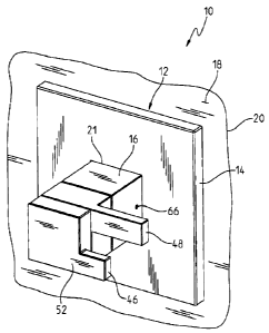
[0025] Referring initially to Figs. 1-4, a shower valve assembly 10 is
shown as including
an escutcheon mounting assembly 12 according to an illustrative embodiment of
the present
disclosure. As further detailed herein, the escutcheon mounting assembly 12
operably couples
an escutcheon 14 to a valve sleeve 16. The valve sleeve 16 is supported by a
vertical mounting
surface 18 defined by a wall 20 and extends through an opening 21 defined by
the escutcheon 14
(Figs. land 4).
[0026] With further reference to Figs. 2-4, the escutcheon mounting
assembly 12 is
coupled to wall 20 through a valve body assembly 22 including a valve housing
24 coupled to a
mounting bracket 26. Using traditional fasteners, such as screws 27, the
bracket 26 is coupled to
a stringer 28 in the wall 20. As is known, the stringer 28 extends
horizontally between at least
two studs 30 in the wall 20 (Fig. 4). The valve body assembly 22 may be of
conventional design
and includes a hot water inlet 32 and a cold water inlet 34 fluidly coupled to
the valve housing
24. Similarly, a first mixed water outlet 36 and a second mixed water outlet
38 may be fluidly
coupled to fluid delivery devices, such as a shower head and a tub spout (not
shown). As is
known, a diverter (not shown) may alternate the flow of mixed water between
the first and
second mixed water outlets 36 and 38. The valve housing 24 includes a cavity
40 configured to
receive a valve cartridge 42.
BDDBOI 5773329v3
CA 02720434 2010-10-06
- 4 -
[0027] As shown in Figs. 2 and 3, the valve cartridge 42 is illustratively
captured within
the valve housing 24 by securing valve sleeve 16 to valve body assembly 22
with traditional
fasteners, such as threaded inserts 44. The valve housing 24 and cartridge 42
extend outwardly
from the wall 20. Illustratively, a first handle 46 is coupled to cartridge 42
for controlling water
temperature, while a second handle 48 is coupled to cartridge 42 for
controlling water flow.
More particularly, operation of handles 46 and 48 causes cartridge 42 to
control the flow of
water from inlets 32 and 34 to respective mixed water outlet 36, 38. The
handles 46 and 48 are
operably coupled to the valve cartridge 42 by a screws 49 and 50,
respectively. An o-ring 51 is
positioned intermediate the second handle 48 and the valve sleeve 16. A front-
end cap or cover
52 is coupled to the outer handle 46 to conceal the screw 50 and make the
handle assembly
aesthetically pleasing. An o-ring 54 may be positioned intermediate the front-
end cap 52 and the
outer handle 46.
[0028] Referring further to Fig. 3, the valve housing 24 extends from the
wall 20 and is
received into valve sleeve 16. Illustratively, the valve sleeve 16 includes a
side wall 58 defining
an outer surface 60 having a plurality of flat surfaces 62. As such, the valve
sleeve 16 includes a
cross-section that is substantially square. The valve cartridge 42 is secured
from rotating relative
to the valve sleeve 16 by traditional fasteners, such as set screws 66. The
valve housing 24
illustratively includes a cylindrical inner surface 68 that conforms to the
shape of the valve
cartridge 42. The valve sleeve 16 is visible to a shower user and adds to the
aesthetic appeal of
the escutcheon mounting assembly 12.
[0029] With reference to Figs. 2, 3, 5 and 6, the escutcheon mounting
assembly 12
further includes a mounting member or base 70. Illustratively, the mounting
member 70
comprises a mounting bracket including opposing first and second bracket
members 74 and 76.
The first and second bracket members 74 and 76 each include laterally
extending bosses 78 and
80 having either a magnet or a magnetically attractive element. In the
illustrative embodiment,
the bosses 78 and 80 of first and second bracket members 74 and 76 each
include a magnetically
attractive element. The magnetically attractive element is illustratively
formed of a magnetically
attractable material, such as iron or steel. In certain illustrative
embodiments, the magnetically
attractive element may be formed of 410 stainless steel or a galvanized steel.
The magnetically
attractive element may also comprise a magnet.
BDUE301 5773329v3
CA 02720434 2010-10-06
- 5 -
[0030] The first and second mounting bracket members 74 and 76 are coupled
together
using traditional fasteners 82 to form a substantially square center opening
86 configured to
receive the valve sleeve 16 (Fig. 5). In this way, the bracket 70 is axially
adjustable as it slides
along the valve sleeve 56 when unclamped. The bracket 70 may then be secured
at a desired
position along sleeve 56. The adjustable nature of the bracket 70 accounts for
varying wall
depths and slides to a position adjacent the wall 20. The mounting bracket 70
includes protective
liners 88 and 90 positioned adjacent the outer surface 60 of the valve sleeve
16. The liners 88
and 90 may be formed of an elastomeric material and aid in resisting axial
movement of the
bracket 70 once it is coupled to the valve sleeve 56. The liners 88 and 90 are
clamped between
the bracket members 74 and 76 and the valve sleeve 56. Additionally, the
liners 88 and 90
protect the valve sleeve 56 in a situation where the bracket 72 is forcibly
removed.
[0031] With reference to Figs. 2, 3, 6 and 7, the mounting bracket 70 is
illustratively
positioned intermediate the vertical wall 20 and a seal 92. The seal 92 is
comprised of a
compressible material such as an elastomer with a center aperture 94 capable
of receiving the
valve sleeve 56. The seal 92 is axially adjustable along the valve sleeve 56
and physically
contacts the mounting bracket 70. As shown in Fig. 6, the seal 92 further
includes a first
aperture 96 and a second aperture 98 on opposite sides of the center aperture
94. The first and
second apertures 96 and 98 are configured to allow for the passage of magnetic
fields.
Illustratively, the first and second opposing apertures 96 and 98 are circular
and positioned to
expose magnets 102 and 104 and magnetically attractive elements 78 and 80.
[0032] In the embodiment shown in Figs. 2 and 3, first and second magnets
102 and 104
releasably couple the escutcheon 14 to the mounting bracket 70. The escutcheon
14 may be
manufactured from magnetically attractable material, such as brass, for
securing the magnets 102
and 104 thereto. Alternately, a fastener or adhesive may be used to secure the
magnets 102 and
104 to the escutcheon 14. The magnets 102 and 104 are positioned on a rear
surface 106 of the
escutcheon 14 such that when the escutcheon 14 is positioned proximate the
mounting bracket
70, the magnets 102 and 104 couple to the magnetically attractive elements 78
and 80. The
escutcheon 14 slides onto the valve sleeve 56 and fits against the seal 92
such that the magnets
102 and 104 align with the first and second apertures 96 and 98 of the seal 92
and couple with
the magnetically attractive elements 78 and 80 on the mounting bracket 70.
BDDBOI 5773329v3
CA 02720434 2010-10-06
-6-
100331 The magnets 102 and 104 of the illustrative embodiment are coated or
plated to
prevent humidity and wetness from corroding and decreasing the magnetic
strength. In the
illustrative embodiment of Fig. 7A, the magnets 102 and 104 may each include a
coating 107,
illustratively a first nickel layer 107a below a copper layer 107b which, in
turn, is below a
second nickel layer 107c to prevent corrosion. An epoxy layer 107d may be
placed over the
second nickel layer 107c to prevent water penetration. In other illustrative
embodiments, the
coating 107 may be formed from other suitable materials, such as a polymeric
overmold.
Suitable types of magnets 102 and 104 are rare earth magnets. In one
illustrative embodiment,
the magnets 102 and 104 are formed from a neodymium magnetic slurry. While the
magnets
102 and 104 in the present embodiment are permanent magnets, it is envisioned
that other
magnets, including electromagnets, could be used.
[0034] The coupling of the magnets 102 and 104 and the magnetically
attractive elements
illustratively generate a total coupling force of up to 25 lbf (i.e.. up to
12.5 lbf per magnet). If an
embodiment includes a gasket positioned between the wall 20 and the mounting
assembly 12,
this coupling force is strong enough to compress the gasket and create a seal
against the wall.
Further, magnets 102 and 104 with a total coupling force of up to 25 lb f can
withstand contact
from someone or something in the shower without inadvertently uncoupling the
escutcheon
mounting assembly 12. Additionally, in the event that the mounting assembly 12
needs to be
repaired or replaced, the coupling force can be overcome to release the
escutcheon 14 from the
mounting bracket 70.
[0035] Magnets 102 and 104 may be of any conventional design. As is known,
magnets
have magnetic fields defined by their strength and orientation. Magnetic poles
are regions in the
magnet where the field of the magnet is most intense, each of which is likened
to a geographic
direction, north (N) or south (S). The direction of the magnetic field is the
direction of a line that
passes through the N and S poles of the magnet. Generally, the direction is
perpendicular to the
magnetic surface of the magnet. The orientation of the magnetic field is the
direction pointed to
by the N pole of the magnet.
[0036] Magnets with a single magnetic field are considered dipolar because
they have
two poles: a N pole and a S pole. The magnetic field of dipolar magnets can
interact with other
BDDBOI 57733293
CA 02720434 2010-10-06
- 7 -
magnetic fields to produce a repelling or an attracting force. Magnets also
may interact with
magnetically attractive materials, such as iron or steel, that are naturally
attracted to magnets.
100371 There are several different types of magnets. A permanent magnet has
a constant,
or permanent, magnetic field. However, an electromagnet generates a magnetic
field only when
a flow of electric current passes through it. The strength of an
electromagnetic field can be
altered by changing the current that flows through the electromagnet. Once the
current stops
flowing through the material, the magnetic field disappears. The magnetic
force of any magnet
may be changed by altering the position of the magnet relative to another
magnet or attractable
material.
[0038] Figs. 5 and 6 shown additional details of the mounting member or
bracket 70 and
liners 88 and 90. Illustratively, the first and second opposing members 74 and
76 of the
mounting bracket 70 are joined with traditional fasteners 82, with the liners
88 and 90 positioned
intermediate the valve sleeve 16 and the mounting bracket 70. As detailed
herein, the liners 88
and 90 may serve multiple purposes. The liners 88 and 90 are a frictional
barrier to prevent the
bracket 70 from moving along the valve sleeve 16, and they protect the valve
sleeve 16 if the
bracket 70 is removed with excessive force. From the rear view of Fig. 5, the
magnetically
attractive elements 78 and 80 coupled to the first and second members 74 and
76 of the bracket
70 are positioned to conceal the first and second apertures 96 and 98 of the
seal 92. In other
words, the magnetically attractive elements 78 and 80 couple with the magnets
102 and 104
through the apertures 96 and 98 in the seal 92. The first and second magnets
102 and 104 also
couple with the rear surface 106 of the escutcheon 14.
100391 The escutcheon mounting assembly 12 is illustratively installed by
working
outwardly from the wall 20. The mounting bracket 26 of the valve body assembly
22 is secured
to a stringer 28 in the wall 20 using conventional fasteners 27. The inlets 32
and 34 are
threadedly coupled to water supplies, and the valve housing 24 receives valve
cartridge 42. The
valve sleeve 16 slides over the valve housing 24 and secures the valve
cartridge 42 using
conventional fasteners 44. The valve sleeve 16 projects from the wall 20 and
has a substantially
square cross-section. A bracket 70, including liners 88 and 90, slide onto the
valve sleeve 16.
The opposing first and second members 74 and 76 of the bracket 70 are
positioned adjacent to
the wall 20 and are secured together using screws 82. Next, seal 92 slides
onto the valve sleeve
BDDBOI 5773329v3
CA 02720434 2010-10-06
-8-
16 and is positioned parallel with the bracket 70. The seal 92 also is
parallel with the escutcheon
14, which is received over the valve sleeve 16 through opening 21. Magnets 102
and 104
coupled to the rear surface 106 of the escutcheon 14 are aligned with the
magnetically attractive
elements 78 and 80 on each of the opposing first and second bracket members 74
and 76. The
magnetic attraction between the magnets 102 and 104 and the magnetically
attractive elements
78 and 80 couples the escutcheon 14 to the mounting bracket 70. A pair of
handles 40 and 48
are operably coupled to the valve cartridge 42 through a screws 49 and 50.
[0040] Figs. 8-15 show a further illustrative embodiment magnetic
escutcheon mounting
assembly 212 for use with an electronic shower valve assembly 210. As further
detailed herein,
the escutcheon mounting assembly 212 includes an escutcheon 214 having an
opening 215 for
receiving an electronic user interface 216 accessible to someone in the
shower. With reference
to Fig. 8, the user interface 216 illustratively includes an interface panel
218 with a plurality of
push buttons 220 related to different fluid delivery options. Illustratively,
a temperature control
input 221, such as a capacitive touch slide sensor disposed on an arcuate
path, is supported by
the interface panel 218 to control outlet water temperature. In a further
illustrative embodiment,
a flow control input 223 may be positioned adjacent the temperature control
input 221 and
configured to control the rate of outlet water flow. Again, the flow control
input 223 may
comprise a capacitive touch slide sensor disposed along an arcuate path. In
alternative
embodiments, a rotatable knob (not shown) may be manipulated by the user to
control the flow
rate and/or temperature of water delivered to the shower. Moreover, the
interface panel 218 is
configured to receive inputs from a user and convert those inputs into an
output that maybe
transmitted to an electric valve (not shown) to provide for specific fluid
temperature, flow rate,
and/or outlet pattern.
[0041] With reference to Figs. 8 and 9, the escutcheon mounting assembly
212 is
configured to be supported by vertical mounting surface 18 defined by the wall
20. As shown in
Figs. 10 and 11. the escutcheon mounting assembly 212 includes a mounting base
236
supporting a user interface 216, and escutcheon 214. Magnets 238, 240 and
magnetically
attractive elements 270, 272 are used to couple the escutcheon 214 to the
mounting base 236.
The mounting base 236 couples to the wall 20 using a plurality of mounting
screws 224 and 226.
Illustratively, a first mounting screw 224 is secured proximate upper edge 228
of the mounting
Bmini 5773329v3
CA 02720434 2010-10-06
- 9 -
base 236 and a second mounting screw 226 is secured proximate lower edge 230
of the mounting
base 236. A seal 246 is compressed between the vertical wall 20 and the
mounting base 236.
The seal 246 may be formed from any compressible material, such as foam.
[0042] The mounting base 236 includes upper edge 228, lower edge 230, and
opposing
side edges 248 and 250. Two recesses 252 and 254 are positioned near the lower
edge 230 of the
mounting base 236. In the illustrative embodiment, the recesses 252 and 254
contain magnets
238 and 240 of substantially the same size and shape as the apertures 252 and
254. The magnets
238 and 240 are illustratively secured to the recesses 252 and 254 of the base
236 using
conventional means, such as through an adhesive or epoxy. Optionally,
magnetically attractive
material may be adhered to the first and second apertures 252 and 254, rather
than magnets 238
and 240. Illustrative magnets 238 and 240 are rare earth magnets. In one
illustrative
embodiment, the magnets 238 and 240 are formed from a neodymium magnetic
slurry. While
the magnets 238 and 240 in the present embodiment are permanent magnets, it is
envisioned that
other magnets, including electromagnets, could be used. The magnets 238 and
240 illustratively
generate a total coupling force of up to 6 lbf (i.e., up to 3 lbf per magnet
238 and 240).
[0043] The magnets 238 and 240 of the illustrative embodiment are coated or
plated to
prevent humidity and wetness from corroding and decreasing the magnetic
strength. For
example, the magnets 238 and 240 may include a coating 255, illustratively an
epoxy material to
prevent corrosion. In other illustrative embodiments, the coating 255 may be
formed from a
polymeric overmold.
[0044] With further reference to Figs. 10-12, mounting base 236 has first
and second
keyhole slots 256 and 258 used to couple the user interface 216 to the
mounting base 236. The
user interface 216 includes first and second locking projections 260 and 262
configured to fit
into the keyhole slots 256 and 258 and securely couple the user interface 216
to the mounting
base 236. Positioned between the user interface 216 and the mounting base 236
is a seal 264.
The seal 264 is placed against a front face 266 of the mounting base 236 (Fig.
10).
[0045] The escutcheon 214 is received over the user interface 216. Located
along the
upper edge 267 of the escutcheon 214 is at least one protrusion or tab 268.
Illustratively, three
protrusions 268a, 268b, 268c are supported proximate the upper edge 267 of the
escutcheon 214.
Located along a lower edge 277 of the escutcheon 214 is at least one
magnetically attractive
BDDBOI 5773329v3
CA 02720434 2010-10-06
- 10 -
element, illustratively 410 stainless steel screws 270 and 272 received into
first and second
internally threaded bosses 274 and 276. The screws 270 and 272 may be replaced
by other
magnetically attractive elements, including magnets. The magnets 238 and 240
proximate the
lower edge 230 of the mounting base 236 are attracted to the magnetically
attractive elements
270 and 272, respectively, and couple the lower edge 277 of the escutcheon 214
to the lower
edge 230 of the mounting base 236. The protrusions 268a, 268b, 268c proximate
the upper edge
267 of the escutcheon 214 are coupled with recesses 278a, 278b, 278c,
respectively, that are
proximate the upper edge 228 of the mounting base 236. The protrusions 268 fit
within the
recesses 278 to form a hinge 284 that pivotally couples the escutcheon 214 to
the mounting
base 236.
[0046] As shown in Figs. 10-12, the keyhole slots 256 and 258 are coupled
with the first
and second locking projections 260 and 262 of the user interface 216. The
locking projections
260 and 262 slide from the upper end of the keyhole slots 256 and 258 to the
lower end to secure
the user interface 216 to the mounting base 236. The escutcheon 214 is coupled
to the mounting
base 236 using magnetic forces. Magnets 238 and 240 adhered to opposing first
and second
recesses 252 and 254 proximate the lower edge 230 of the mounting base 236 are
attracted to the
stainless steel screws 270 and 272 proximate the lower edge 277 of the
escutcheon 214. In this
way, the use of magnets 238 and 240 makes the escutcheon 214 more
aesthetically pleasing
because they are not visible to a user. Magnets 238 and 240 are hidden
fastening means, not
visible on the exterior of the escutcheon 214 in the way that conventional
fasteners would be,
and therefore, the shower valve assembly 210 has an aesthetically pleasing
appearance.
100471 Turning now to Figs. 14 and 15, hinge 284 is defined by the
protrusion 268 of the
escutcheon 214 and the recess 278 of the base 236. The hinge 284 is movable
between an open
position (Fig. 14) and closed position (Fig. 15). The protrusions 268
proximate the upper edge
267 of the escutcheon 214 fit into the recesses 278 proximate the upper edge
228 of the
mounting base 236 to form hinge 284. The hinge 284 pivotally couples the
escutcheon 214 to
the mounting base 236. Fig. 14 shows the hinge 284 in an open position,
defined by the
escutcheon 214 in a nonparallel position relative to the mounting base 236.
When the hinge 284
is in the open position, the escutcheon 214 is supported by the base 236 at
only the hinge 284.
The magnets 238 and 240 and magnetically attractive elements 270 and 272 are
not coupled
BDDBOI 5773329v3
CA 02720434 2013-03-28
-1 1-
together. The escutcheon 214 is configured to pivot at the hinge 284 and move
downward
toward the closed position, as shown in FIG. 15.
100481 More particularly, the closed position of the hinge 284 is defined
by the
escutcheon 214 in a parallel relation to the mounting base 236 (FIG. 15). In
the closed
position, the escutcheon 214 is supported by both the hinge 284 proximate the
upper edges
267 and 228 of the escutcheon 214 and the mounting base 236 and the magnetic
coupling
force resulting from the magnets 238 and 240 and the magnetically attractive
elements 270
and 272 near the lower edges 230 and 277 of the mounting base 236 and the
escutcheon 214.
100491 The escutcheon mounting assembly 212 is illustratively assembled by
attaching the mounting base 236 to vertical wall 20 through screws 224 and
226. Seal 246 is
positioned intermediate the wall 20 and the mounting base 236. With the base
236 secured to
the wall 20, seal 264 is positioned in engagement with the front face 266 of
the mounting base
236 and is compressed by the attachment of the user interface 216 to the
mounting base 236.
The user interface 216 couples to the mounting base 236 through keyhole slots
256 and 258
and locking projections 260 and 262. Once the user interface 216 is secured to
the mounting
base 236, the escutcheon 214 is attached. The protrusions 268 proximate the
upper edge 267
of the escutcheon 214 is received within the recesses 278 proximate the upper
edge 228 of the
mounting base 236. The escutcheon 214 is pivoted downwardly until the magnets
238 and
240 couple with the magnetically attractive elements 270 and 272. In this way,
the escutcheon
mounting assembly 12 is coupled proximate both the upper edges 228 and 267 and
the lower
edges 230 and 277 if the mounting base 236 and the escutcheon 214.
100501 Although the invention has been described in detail with reference
to certain
preferred embodiments, the scope of the claims should not be limited by the
preferred
embodiments set forth in the examples, but should be given the broadest
interpretation
consistent with the description as a whole.