Note: Descriptions are shown in the official language in which they were submitted.
CA 02720453 2010-10-01
WO 2009/124199 PCT/US2009/039335
Attorney Docket No. 3873.LBRI.PC
TITLE
HANDS-FREE BREAST PUMP SYSTEM
1. The Field of the Invention
The present invention relates to breast-milk collection systems. More
specifically,
the present invention relates to hands-free breast pump systems.
2. State of the Art
Studies show that mother's breast milk is more healthy for infants than
formula or
other types of milk. Mothers strive to provide the best environment for their
children.
Sometimes this requires that the mother cannot be with a nursing infant at all
times. For
example, some women work some amount of time during the day. Nursing mothers
that
work must collect milk during the day to provide breast milk for her child
when she is away
from her child. If a nursing mother does not pump, her milk production can
wane, such that
she is not able to produce enough milk for her infant. Thus, many working
mothers collect
breast milk to be able to work and provide the best nourishment for their
infants. To
accommodate nursing mothers, breast pumps for expressing breast milk for later
use by her
infant have been around for some time.
Typically, these breast pumps include a funnel, or parabolic-shaped cup,
similar to a
suction cup, which is placed over the nipple and a portion of the breast. The
cup is generally
connected to a container for holding the expressed milk and a vacuum pump of
some type.
Some pumps may be hand-activated, while others are electrically operated. Some
are even
battery powered.
A vacuum from the pump is generally intermittently generated within the shield
to
generate negative pressure on the nipple, causing milk to be expressed from
the breast
within the cup. The intermittent nature of the vacuum may be done to simulate
a baby
sucking at the breast for milk. The expressed milk then generally flows from
the shield to a
storage container for later use. Most breast pumps require that the woman use
her hands to
operate the pump and/or maintain connection with the cup and her breast. Such
breast
pumps have been time consuming and somewhat awkward to use because the woman
using
CA 02720453 2010-10-01
WO 2009/124199 PCT/US2009/039335
2
the pump must occupy her hands, making it difficult or impossible to perform
other
activities.
A variety of breast pumps have been developed that are intended to allow a
woman's hands to be free during use of the breast pump. Often, these breast
pumps utilize
straps, or bra-type structures for holding the shield in the place during milk
expression.
However, these straps and other structures generally provide for additional
bulk in the breast
pump and are difficult and time consuming to attach, which is not conducive to
pumping in
locations other than home where the pump may be stored. Some women desire to
be out of
the house during times when she would need to pump breast milk to maintain
milk
production. Other pumps require special bras or other clothing, requiring
often
uncomfortable choices in clothing. Similarly, may breast pumps on the market
are
uncomfortable, and difficult to use. Thus, a need exists for simple,
comfortable, hands-free
breast pump.
SUMMARY OF THE INVENTION
Embodiments of hands-free breast pump systems, methods, and components are
described. Some embodiments of breast pump systems may include a formed
member, or
breast shield, made of a material that provides for an adhesive inner surface
for adhering to a
woman's breast. The adhesiveness of the surface is due to the materials used
during
manufacturing, and not due to adhesive sprays, lotions, or other items placed
on the breast
shield or the breast by the end-user.
In some embodiments, breast pump systems may include an adapter connected to
the breast shield for transferring a vacuum generated by a pump to the breast
to express
milk. The adapter also allows milk expressed from the breast to drain from the
adapter to a
container, without travelling into the pump. In some embodiments, the breast
shield adheres
to the breast and supports the weight of the adapter, breast shield, and
tubing extending from
the adaptor without separate adhesives, gels, straps, or specially designed
support bras.
Thus, the adhesive breast shield and breast pump system may allow for hand-
free expression
of milk.
CA 02720453 2010-10-01
WO 2009/124199 PCT/US2009/039335
3
BRIEF DESCRIPTION OF THE DRAWINGS
Various embodiments are shown and described in reference to the numbered
drawings wherein:
FIG. 1 illustrates a generalized schematic view of an exemplary embodiment of
a
breast pump system;
FIG. 2 illustrates a generalized schematic view of an exemplary embodiment of
a
breast pump system;
FIG. 3 illustrates a partial assembly of an exemplary breast pump system;
FIG. 4 illustrates components of a partial assembly of an exemplary breast
pump
system;
FIG. 5 illustrates a partial assembly of an exemplary breast pump system
FIG. 6 illustrates a cross-sectional view of a lid assembly of an exemplary
breast
pump system;
FIGS. 7 through 9 illustrate views of exemplary breast shields of exemplary
embodiments of a breast pump system.
Together with the following description, the Figures demonstrate and explain
the
principles of patient positioning systems and associated components and
methods. In the
Figures, the thickness and configuration of components may be exaggerated for
clarity.
The same reference numerals in different Figures represent the same component.
DETAILED DESCRIPTION
Embodiments of a hands-free breast pump system are described below and shown
in
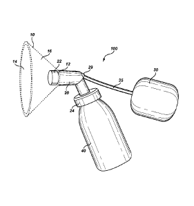
the Figures. Breast pump system 100, as shown in Fig. 1, includes breast
shield 10, adapter
20, pump 30, vacuum line 35, vacuum line connector 29, container connector 24,
and
container 40.
Breast shield 10 may have outer surface 16 and an inner surface 14. Breast
shield 10
may be made of a soft flexible material capable of conforming to a woman's
breast. Inner
surface 14 may be adhesive in nature so that breast shield 10 will adhere to a
woman's
breast. Because of the adherent nature of inner surface 14 of breast shield
10, inner surface
14 may attract dirt, lint, skin cells, oil, and other materials that may
reduce the adhesiveness
of inner surface 14. In that situation, inner surface 14 may be washed with
soap and water,
CA 02720453 2010-10-01
WO 2009/124199 PCT/US2009/039335
4
boiled, or otherwise cleaned to restore the adhesiveness of inner surface 14.
Overtime,
breast shield 10 may become worn, lose some adhesion properties, or otherwise
require
replacement. In such cases, breast shield 10 may be removed from adaptor 20
and replaced
as necessary.
The adhesive nature of inner surface 14 of breast shield 10 may allow breast
shield
to remain affixed to a woman's breast during the duration required to express
a required
or desired amount of milk or until dry. Thus breast shield 10 may be used in a
hands-free
manner without the need for separate consumer applied adhesives, gels, straps,
or specialty
bras designed for holding a breast pump system in place. Similarly, it allows
use of breast
10 pump system 100 without requiring the woman to hold breast shield 10 in
place with her
hands. Therefore, a woman using breast shield 10 with pump system 100 may be
able to
express milk and still have use of her hands for other activities.
Additionally, breast shield
10 may be more comfortable than previously known breast shields because it
conforms to
the breast.
Breast shield 10 may be made from any appropriate material that imparts the
desired
attributes of flexibility and adhesiveness to skin. In certain embodiments,
breast shield 10
may be made from an elastomeric material that has been sufficiently
plasticized along inner
surface 14 to provide the desired material characteristics. For example,
breast shield 10 may
be made from a silicone rubber with suitable plasticizers. In other examples,
breast shield
10 may be made from Styrene-Ethylene-Butylene-Styrene (SEBS), Styrene-Ethylene-
Propylene-Styrene (SEPS), and Styrene-Ethylene-Ethylene-Propylene-Styrene
(SEEPS)
copolymers. Other materials may also be appropriate. For example, suitable
plasticizers for
elastomers may include oils such as mineral oils, resins, rosins, and others.
Other
components may be used with the elastomers as well, such as antioxidants,
colorants, bleed
reducing additives, etc. In some embodiments, a coating may be applied during
manufacture to provide the necessary adhesion properties. Depending on the
desired
structure, rigidity, softness, etc., any suitable process or materials may be
used to construct
breast shield 10, as desired. For example, in some instances it may be
desirable to have
more or less rigidity than others.
The material used in forming breast shield 10 may be manufactured by solvent
blending, melt blending, or compounding under heat and pressure such as by use
of a single
CA 02720453 2016-03-18
screw or twin screw compounding machine or otherwise. Breast shield 10 may be
constructed by injection molding, casting, or another desired process.
Breast shield 10 may be configured in any shape and dimension compatible with
a
woman's breast, as desired. For example, some embodiments of breast shield 10
may be
5 funnel-shaped or cup-shaped. It should be understood that breast shield
10 may be produced
and marketed in a number of sizes and shapes in order to be compatible with a
wide range of
breast dimensions, profiles, and shapes. Breast shield 10 may include opening
12 for
connecting breast shield 10 to connector sleeve 22 of adapter 20. Breast
shield 10 may also
be manufactured to work with known breast pump systems.
In some embodiments, breast shield 10 may be able to invert, such that inner
surface
14 is temporarily on the outside and outer surface 16 is temporarily on the
inside. By
inverting breast shield 10 a woman using breast pump system 100 may be able to
achieve a
tighter, more secure fit. A woman may first place opening of connector sleeve
22 over
the nipple in a desired position, and then extending or rolling breast shield
10 over the
breast as breast shield is returned to the normal state, ensuring maximum
contact, fit,
and adhesion between breast shield 10 and the breast.
Turning now to adapter 20, embodiments of adapter 20 may provide for
introducing
a vacuum to the woman's breast and for directing the flow of milk to container
40. Adapter
may include a connector for connecting to breast shield 10. For example,
adapter 20 may
20 include connector sleeve 22 that forms an interference connection with
opening 12 and inner
surface 14 of breast shield 10. Opening 12 may be stretched around sleeve 22
to form the
interference fit. The end of sleeve 22 may be configured to seal against or
around the areola
of a breast. Sleeve 22 may also be configured so that the nipple of the breast
extends inside
sleeve 22. Inner surface 14 may be configured to adhere to the skin of the
breast
surrounding the areola.
In some embodiments, sleeve 22 may be generally flush with opening 12. For
example, sleeve 22 may include a groove or lip on or near the edge extending
into breast
shield 10 for holding the inside of opening 12. Similarly, opening 12 of
breast shield 10
may include a complimentary structure to allow coupling of sleeve 22 and
breast shield 10.
In other embodiments, adapter 20 and breast shield 10 may be a unitary
structure.
CA 02720453 2010-10-01
WO 2009/124199 PCT/US2009/039335
6
Adapter 20 may include connector 24 for connecting adaptor 20 to container 40.
For
example, connector 24 may be threaded to engage threads on container 40.
Adapter 20 may
be configured such that milk drawn into adapter 20 drains into container 40,
without going
into pump 30. Container 40 may be any container used for receiving expressed
milk or a
modification thereof. For example, container 40 may be a standard baby bottle,
or other
container commonly used to store and/or deliver milk to an infant.
Adapter 20 may be connected through vacuum line connector 29 to pump 30 via
vacuum line 35. Negative pressure generated by pump 30 may be transmitted to
adapter 20
via vacuum line 35 and thereby to the interior of breast shield 10 and sleeve
22. Pump 30
may be any pump or device suitable for delivering vacuum pressure sufficient
for expressing
milk. Vacuum line 35 may be made of any material capable of transferring
negative
pressure from pump 30 to adapter 20, and may be any desired configuration. For
example,
vacuum line 35 may be plastic tubing, such as Polyvinyl Chloride (PVC) tubing.
Vacuum line 35 may be connected to pump 30 and vacuum line connector 29 of
adapter 20 via any type of connector desired. For example, vacuum line
connector 29 may
include an opening about the same diameter or slightly smaller that the outer
diameter of
vacuum line 35, providing for a press or interference fit of the outside of
vacuum line into
adaptor 20. Similarly, vacuum line connector 29 may include an inner flange
for an
appropriate fit with the inner surface of vacuum line 35. Similarly, vacuum
line connector
29 may be oriented in any desired direction from connector 20, depending on
the desired
location of pump 30. For example, vacuum line connector 29 may be oriented
such that
vacuum line 35 extends collinearly with drain line 45 to minimize the profile
of adaptor 20
when attached to a breast.
In some embodiments, adapter 20 may be specially designed to meet the
functional
requirements described herein. In any of the embodiments, it may be desirable
to have
adapter 20 be as small as possible to reduce the weight of adapter 20.
Similarly, adaptor 20
may be made of light materials to reduce the weight being born by breast
shield 10, and the
woman's breast. Adaptor 20 may also be manufactured to be compatible with any
desired
commercially available pump.
FIG. 2 illustrates other embodiments of breast pump system 100 similar to
embodiments shown in Fig. 1. In Fig. 2, container 40 is coupled to adapter 20
via drain line
CA 02720453 2010-10-01
WO 2009/124199
PCT/US2009/039335
7
45. Drain line 45 may be coupled to adaptor 20 and container connector 24.
Container
connector 24 may contain a valve that closes when negative pressure is
generated by pump
30, creating a vacuum. This valve would open when the pump cycles off the
negative
pressure, allowing milk to drain into container 40. Similarly, such a valve
may be located
on adaptor 20, or as an in-line valve in drain line 45. Drain line 45 may be
long enough that
container 40 may be supported by something other than adapter 20. For example,
container
40 may rest on a table or chair while a woman is expressing milk, or may be
held on a belt
or other supporting structure. Drain line 45 may be any device capable of
transferring milk
from adapter 20 to container 40. For example, drain line 45 may be plastic
tubing, such as
PVC tubing. Drain line 45 may be connected to adapter 20 and container 40 via
any type of
connection means desired. In some embodiments, such as is shown in Fig. 5,
adaptor 20
may be able to connect directly to container 40, or to drain line 45, as
desired.
Reducing the weight that must be supported by adapter 20 reduces the weight
that
must be supported by the adhesive connection of breast shield 10 to a woman's
breast, and
consequently, by the woman's breast. Therefore, the embodiments of Fig. 2
reduces the
adhesion required in the embodiments of Fig. 1 for breast shield 10 to stay
adhesively
connected to a woman's breast in a hands-free manner.
Fig. 3 illustrates the interior of and embodiment of connector 20. Connector
20 may
include interior passageway 28 divided into liquid passageway 26 and vacuum
passageway
27 by diverter 23. Diverter 23 may be positioned to prevent expressed milk
from being
sucked into pump 30. When in use, milk will be expressed into passageway 28.
Diverter 23
channels the milk down liquid passageway 26, and further down by gravity into
container
40. Vacuum line connector 29 is attached to pump 30, which supplies the
negative pressure
to express the milk.
Fig. 4 illustrates components of unassembled breast pump system 100 as may be
provided to an end user. System 100 may include breast shield 10, adapter 20,
line
connector 46, vacuum line 35, and drain line 45. Line connector 46 may be
placed in the
opening of a fluid storage container, such as container 40. Line connector 46
may be
coupled to both vacuum line 35 and drain line 45, with vacuum line 35 going to
a pump,
such as pump 30, and drain line 45 going to adaptor 20. In some embodiments,
vacuum line
connector 29 may be capped, as the vacuum is drawn through container 40 and
drain line
CA 02720453 2010-10-01
WO 2009/124199 PCT/US2009/039335
8
45, instead of directly through adaptor 20. Similarly, in some embodiments,
both lines 35
and 45 may function as drain lines 45 running from dual adaptors 10 to the
same container
40 through line connector 46.
Fig. 5 illustrates twin drain lines 45 connected to twin adaptors 20 and
breast shields
10 that may be used to express milk from both breasts simultaneously. A single
or multiple
pumps may be coupled to adaptors 20 as required. Similarly, each of drain
lines 45 may be
connected to the same or a different container 40, and may be connected
together with a "Y"
connector to drain into a single bottle through a single drain line 45.
Similarly, a single
vacuum line from a single pump may be split with a "Y" connector to attach to
both
adaptors 20. It will be understood that lines 35 and 45 may be connected in
any manner to
their respective devices and locations, similar to as discussed with respect
to vacuum line
connector 29 above.
FIG. 6 illustrates a portion of an exemplary breast pump system with container
connector 124. Container connector 124 may include valve 137 connected to
vacuum line
35 through vacuum line connector 129. Container connector 124 may be coupled
to fluid
container 40 and drain line 45 similar to embodiments of connector 24
discussed above.
However, container connector 124 may allow drain line 45 to both carry the
expressed milk
to fluid container 40, and to carry the vaccum pressure from vacuum line 35,
making it
possible to have only one connection to adaptor 20, as previously described.
Valve 137 may include collapsible bladder 139, which may collapse as a vacuum
is
drawn from vacuum line 35, thus producing a pressure drop in fluid container
40, drain line
45 and adaptor 20 sufficient to cause milk from a lactating woman's breast to
be expressed.
The expressed milk may then be drawn down drain line 45 into fluid container
40. Valve
137 may also include air passageways 138 in communication with the interior of
fluid
container 40.
Container connector 124 may be connected to fluid container 40 with a threaded
connection, similar to the connection of connector 24 to fluid container 40
described above.
Burp valve 150 may provide for the expulsion of excess pressure from fluid
container 40 as
milk collects in container 40 to allow valve 137 to continue to provide
negative pressure to
fluid container 40 and drain line 45.
CA 02720453 2016-03-18
9
In some embodiments, valve 137 may be an in-line valve placed in vacuum line
35,
and may be constructed in any manner that allows a vacuum to be drawn in drain
line 45
while eliminating the possibility of fluid from travelling from fluid
container 40 through
vacuum line 35 an into pump 30. In some embodiments, valve 137 may not be
needed,
depending on the configuration of the various parts and components of the
breast pump
System.
FIGS. 7 through 9 illustrate exemplary embodiments of breast shield 10 of
Figs. 1-5,
Each of breast shields 310, 410, 510 includes surface features 318, 418, 518,
respectively.
Breast shield 310 includes surface features 318 resembling flower pedals
extending
outwardly from adaptor 20. Similarly, breast shield 410 includes surface
features 418
resembling bubbles, and breast shield 510 includes surface features 518
resembling leaves
or other nature-styled images. Surface features 318, 418, 518 may provide
structure, and
may provide additional adhesion for inner surface 14. Similarly, as shown in
the Figures,
adaptor 20 may be provided in a number of different profiles and designs.
It should be understood the disclosed embodiments of the disclosed embodiments
of
breast pump systems are exemplary only and do not limit the breadth of the
disclosure.
Likewise, it should be understood that the shape, material, edge design, and
surface area of
the illustrated embodiments are only exemplary of embodiments of breast
shields and are
not limiting, as breast shields falling within the scope of the appended
claims may have
different shapes, edge profiles, etc., while performing the same function.