Note: Descriptions are shown in the official language in which they were submitted.
CA 02720489 2010-11-08
1 "HYDRAULICALLY SET LINER HANGER"
2
3
4 FIELD OF THE INVENTION
The invention relates to liner hanger apparatus used for carrying
6 and anchoring a casing liner in a wellbore casing.
7
8 BACKGROUND OF THE INVENTION
9 Liner hangers are well known in wellbore drilling and completion
operations. Following drilling of at least a segment of a wellbore, a metallic
11 casing is positioned into the open hole and cemented into place. Drilling
is
12 continued below the cemented casing to extend the depth of the wellbore. At
13 least a second length of smaller diameter casing is lowered into the
extended
14 wellbore on a tubular workstring equipped with a liner hanger and is
positioned
near a bottom end of the existing cemented casing. Typically, liner hangers
are
16 equipped with mechanically or hydraulically actuated slips which, when
actuated
17 downhole, act to grip the walls of the existing casing and support the
substantial
18 weight of the depending liner until such time as the new liner can be
cemented
19 into place. This procedure may be repeated more than once, until the
wellbore
has reached an effective depth, the diameter of each subsequent length of
liner
21 being smaller than the previous.
22 Hanger capacity, the amount of weight the hanger can support, is
23 of great concern. Ideally, in order to keep the effective diameter of the
wellbore
24 within acceptable limits, it is desirable to hang as long a length of liner
as can be
supported by the liner hanger.
CA 02720489 2010-11-08
1 Attempts have been made to improve hanger capacity by
2 increasing the number of slips and their arrangement in the tool. US Patent
3 4,926,936 to Braddick teaches a liner hanger having a plurality of
4 circumferentially and vertically spaced slips. Cones for actuation of a
plurality of
slips are attached to a tubular body using rings and are positioned relative
to
6 slips which are attached by arms to a sleeve which overlies the body and is
7 axially moveable thereon, the entirety of the arms and slips being
vulnerable to
8 mechanical contact as the hanger is run into the wellbore. Axial movement of
the
9 sleeve, either mechanically or hydraulically, engages the slips with the
cones
causing the slips to engage the casing. The number of vertical sets of slips
which
11 equates to the liner hanger's support capability is limited by the space
between
12 the lower circumferentially spaced slips which is required to accommodate
the
13 arms extending vertically from the sleeve. Further, fluid passage in the
annular
14 space between the casing and the liner hanger is impeded as the number of
slip
arms increases. Typically, there is little clearance between the outer
surfaces of
16 the liner hanger wall and the casing so as to permit the largest possible
bore
17 through the center of the liner hanger.
18 US patent 4,603,743 to Lindsey Jr. teaches a hydraulically or
19 mechanically set liner hanger having tandem, longitudinally spaced slips
extending on straps from a tubular cage member, which is axially moveable on a
21 tool body. The slips are held in a retracted position by a running tool as
the liner
22 hanger is run into the wellbore. A pressure housing on the running tool is
axially
23 moveable on the running tool's mandrel and is actuated to shift, causing
the
24 cage on the liner hanger to shift, engaging cam faces on a slip expander
housing
2
CA 02720489 2010-11-08
1 and causing the slips to move outwards into engagement with the casing. The
2 expander housing has rectangular openings which extend through the wall of
the
3 housing. A tieback sleeve is located below the liner hanger and above the
liner.
4 The position of the tieback sleeve, in combination with the rectangular
openings
in the housing, prevents its use for incorporating a liner top packer into
Lindsey's
6 liner hanger system.
7 Liner hangers are known wherein the liner can be rotated, not only
8 during insertion into the wellbore, but also during cementing following
setting of
9 the liner hanger slips. Depending upon the circumstances, it may be
advantageous to rotate the liner during cementing such as to ensure a uniform
11 distribution of cement in the casing annulus as well as proper displacement
of
12 the drilling mud, without channeling of the cement through the mud. US
Patents
13 5,181,570 to Allwin et al., 5,048,612 to Cochran and 4,848,462 to Aliwin,
teach
14 rotatable liner hangers.
During cementing excess drilling fluid is displaced upwardly
16 between the liner hanger and the cemented casing. Restriction in the fluid
flow is
17 undesirable.
18 There is a need for a liner hanger system having a large hanging
19 capacity to permit hanging of long or heavy lengths of liner and maximum
fluid
bypass to eliminate any problems with fluid flow during cementing. Preferably,
21 the slips should be protected from damage as a result of irregularities in
the
22 borehole. Ideally, the liner hanger should have a simplified manufacture.
Ideally,
23 liner hangers having these characteristics should be available in both non-
3
CA 02720489 2010-11-08
1 rotating and rotating configurations for use in a wide variety of cementing
2 operations.
4
CA 02720489 2010-11-08
1 SUMMARY OF THE INVENTION
2 Generally, a liner hanger comprises a slip housing axially
3 moveable over a mandrel. The slip housing has a plurality of slip openings
which
4 contain slips. Relative axial movement of the slip housing over the mandrel
cause actuation of the slips over cams supported on the mandrel. Fluid flow
6 bypass is increased between the hanger and the casing by implementing
7 additional bypass between the mandrel and the slip housing in an annular
space
8 formed therebetween. Bypass is unimpeded therein due to the circumferential
9 arrangement of spaced slips. Sets of slips can be positioned axially along
the
length of the slip housing. The plurality of sets of slips results in an
increased
11 hanging capacity. The number of sets that can be applied is limited only by
the
12 length of the slip housing itself. Preferably, fluid bypass is further
increased by
13 profiling an inner surface of the housing.
14 In one broad aspect of the invention, a non-rotatable liner hanger
comprises: a tubular mandrel having a slip housing axially moveable thereon
and
16 defining an annular space therebetween, the slip housing having an inlet
and an
17 outlet for permitting the flow of fluids through the annular space; one or
more
18 sets of slips housed in a plurality of openings in the slip housing and
more
19 preferably two or more sets of slips, each slip in each set of slips being
spaced
circumferentially for passage of fluids therebetween, each of the one or more
21 sets of slips being spaced axially along the slip housing, preferably
biased into
22 the slip housing in a stowed position during running of the tool; cam
surfaces
23 extending radially outward from the mandrel and corresponding with each
slip;
24 and an actuator attached to the mandrel for axially moving the slip housing
for
5
CA 02720489 2010-11-08
1 engaging the slips with the cam surfaces and causing the slips to move from
the
2 stowed position to a radially extended position for engaging the existing
casing.
3 The cam surfaces are supported by the mandrel and extend
4 radially therefrom, preferably machined from an external surface of the
mandrel
to improve structural rigidity. The cam surfaces can alternatively extend from
a
6 cam sleeve positioned rotationally between the slip housing and the mandrel.
7 In a second broad aspect of the invention, a rotatable liner hanger
8 comprises incorporation of the cams on a sleeve between the slip housing and
9 the mandrel. Accordingly the rotatable liner hanger comprises: a tubular
mandrel
having a slip housing axially moveable thereon and defining an annular space
11 therebetween, the slip housing having an inlet and an outlet for permitting
the
12 flow of fluids through the annular space; one or more sets of slips housed
in a
13 plurality of openings in the slip housing and more preferably two or more
sets,
14 each slip in a set of slips being spaced circumferentially for passage of
fluids
therebetween, each of the one or more sets of slips being spaced axially along
16 the slip housing; a cam sleeve rotationally supported in the annular space,
the
17 cam sleeve having cam surfaces extending radially outward for urging the
slips
18 on the slip housing to a radially extended position while permitting the
mandrel to
19 rotate freely when the slips engage the casing; and hydraulic means
attached to
the mandrel for axially moving the slip housing for engaging the slips with
the
21 cam surfaces and causing the slips to move to a radially extended position
for
22 engaging the existing casing.
23 In both the rotating and non-rotating embodiments, the means
24 acting between the slips and the slip housing to bias the slips into the
slip
6
CA 02720489 2010-11-08
1 housing during running in of the tool are springs attached to the slips and
2 extending laterally therefrom between the slip housing and the mandrel.
3 Preferably, the hydraulic means or actuator for actuating the slip
4 housing to move axially to set the slips is a piston in fluid communication
with the
bore of the mandrel, such that pressure in the bore to causes the piston to
move
6 uphole and actuate the slip housing.
7 Optionally, both rotating and non-rotating embodiments may have
8 a collet system which acts to prevent premature axial movement of the slip
9 housing while running in the tool. The collet system is positioned between
the
hydraulic section and the slip housing. A shear screw acts to retain a collet
11 retainer between a collet housing and collet fingers to prevent the collet
from
12 releasing from a profile in the mandrel until such time as the mandrel's
bore is
13 pressurized sufficiently to actuate the piston in the hydraulic section.
Both the
14 retainer shear screw and a main shear screw between the collet housing and
the
mandrel must be sheared to permit actuation of the slips.
16 Further, in the rotating embodiment, so as to avoid imparting
17 rotational energy to the hydraulic section, the piston is preferably formed
in two
18 sections, a lower section carrying seals which can rotate with the
hydraulic
19 section and an upper section which bears against the non-rotating collet
retainer.
7
CA 02720489 2010-11-08
1 BRIEF DESCRIPTION OF THE DRAWINGS
2 Figure 1 is a longitudinal partial sectional view of a liner hanger of
3 the present invention;
4 Figure 2 is a cross-sectional view according to Figure 1, sectioned
along lines A-A and showing the slips in a retracted position;
6 Figure 3 is a cross-sectional view according to Figure 1, sectioned
7 along lines A-A and showing the slips in an extended position;
8 Figure 4a is a front perspective view of a slip removed from the slip
9 housing;
Figure 4b is a rear perspective view of the slip according to Fig. 4a,
11 illustrating the positioning of a laterally extending spring connected to
the slip;
12 Figure 5a is a rollout view of a slip housing having two sets of
13 vertically positioned slips and illustrating, in dashed lines, a pattern of
a flow of
14 fluids between the plurality of slips;
Figure 5b is a rollout view of a slip housing having two tiers of
16 vertically positioned slips and option flow openings and illustrating, in
dashed
17 lines, a pattern of flow of fluids between the plurality of slips;
18 Figure 6a is a longitudinal sectional view of a hydraulic portion of
19 the liner hanger according to Fig. 1, the right side illustrating a non-
actuated
position and the left side illustrating an actuated position;
21 Figure 6b is a sectional view of an optional collet system the right
22 side illustrating a non-actuated position and the left side illustrating an
actuated
23 position;
8
CA 02720489 2010-11-08
1 Figures 7a-c are partial longitudinal sectional views of a second
2 embodiment of the invention in which the casing can be rotated during
3 cementing, illustrated in sections, Fig. 7a being an uphole section, Fig. 7b
being
4 an intermediate section and Fig. 7c being a downhole section, all of which
are
shown in a non-actuated position;
6 Figure 8 is a partial longitudinal view illustrating embodiments of
7 the liner hanger according to Figs. 1 and 7a-c and optionally having either
a
8 single set of slips, two sets of slips or three sets of slips; and
9 Figure 9 is a longitudinal, partially sectioned view of a liner hanger
assembly including the liner hanger according to Fig. 1.
9
CA 02720489 2010-11-08
1 DETAILED DESCRIPTION OF THE PREFERRED EMBODIMENT
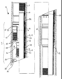
2 Having reference to Figs. 1 - 3, a first non-rotating embodiment of a
3 liner hanger 10 of the present invention is shown in a wellbore casing 11.
The
4 liner hanger 10 comprises an uphole slip portion S and a downhole hydraulic
portion H for actuating the slip portion S. The liner hanger 10 has a tubular
6 mandrel 12 having cam faces 13 supported by and extending radially outward
7 therefrom. For additional structural integrity, the cam faces 13 are
machined
8 integral from the mandrel.
9 A slip housing 14 is mounted on the mandrel 12 and is axially
moveable thereon. A plurality of openings 15 are formed in the slip housing 14
to
11 accommodate a plurality of slips 16. The slips 16 are pivotally retained
within the
12 slip housing 14 and are normally retracted within the openings 15. A slip
13 housing/mandrel annulus 18 is formed between the slip housing 14 and the
14 mandrel 12. The slip housing/mandrel annulus 18 acts to provide additional
fluid
bypass for the flow of drilling fluids, displaced upwardly, during cementing.
16 Laterally extending biasing means 17, shown in greater detail in
17 Figs. 4a - 4b, are connected between the slips 16 and the slip housing 14,
18 extending across and beyond each opening 15. The biasing means 17 act to
19 normally retract the slips 16 into a radially stowed position in the
openings 15 in
the slip housing 14, during insertion of the liner hanger 10 into the casing
11. In
21 operation, the slip housing 14 is caused to move axially on the mandrel 12
so as
22 to engage the slips 16 with the cam faces 13 resulting in extension of the
slips
23 16 into engagement with the casing 11 for gripping the casing 11 and
supporting
24 a liner (not shown) extending therefrom.
CA 02720489 2010-11-08
1 In a preferred embodiment, as shown in Figs. 4a, 4b and 5, the
2 laterally extending biasing means 17 is a flat spring 19 and each slip 16 is
3 attached to the corresponding spring 19 using a fastener 20, such as a
screw.
4 Additionally, as shown in Fig. 5a, mechanical, cantilevered supports, formed
as
tabs 21, extend from the slip housing 14 into opposing sides of each opening
15
6 at a downhole end 22 of each slip 16 to ensure the slips 16 remain biased to
slip
7 housing 14 and to assist in supporting the slips 16 when extended to grip
the
8 casing 11. The supports are formed as tabs 21 on either side of the opening
15,
9 rather than as a solid bar across the opening 15, to ensure that the support
will
bend rather than break under stress should the casing 11 be oversized and the
11 slips 16 over-extend to grip the casing 11.
12 Preferably, the slip housing 14 is assembled as two or more clam-
13 shell portions assembled over the mandrel 12 and welded together, such as
14 through section ring portion at the uphole and downhole ends of the slip
housing.
Further, as shown in Fig. 5a, the slip housing 14 is slit, above and
16 below each tab 21 at an interface 34 between the tab 21 and the slip
housing 14,
17 to decrease bending stress rather than risk breaking of the tab 21 under
undue
18 stress. The slit 35 is locally widened at a distal end 36 to avoid a stress
19 concentration.
The slip housing 14 has a plurality of fluid inlet ports 30 formed at a
21 downhole end 31 of the slip housing 14 and a substantially circumferential
outlet
22 32 formed at an uphole end of the slip housing 14.
23 As shown in Figs. 2, 3 and 5a, the annulus 18 can be further
24 increased in cross-sectional area to provide increased fluid bypass. The
slip
11
CA 02720489 2010-11-08
1 housing 14 is profiled on an inner surface 33 to provide the increased fluid
flow
2 bypass I by creating the enlarged annular space 18 between the mandrel 12
3 and the slip housing 14. The profiling can be a simple concavity resulting
in a
4 thinning of the wall of the slip housing 14.
The fluid flow bypass aids in passing well fluids during operations
6 for cementing the newly hung liner into the wellbore. Cement is pumped
through
7 a bore in a liner hanger system, which simplistically includes a running
tool
8 suspended from a tubing string to surface and connected at a downhole end to
9 the liner hanger, the depending liner and at a distal end to a float shoe.
As
cement exits the float shoe and rises to fill an annulus between the casing 11
11 and the open wellbore (not shown), drilling fluid is displaced upwards and
must
12 pass by the liner hanger 10. When the drilling fluid reaches the cemented
casing
13 11, the fluid is forced between the liner hanger 10 and the casing 11. The
14 displaced fluid enters the casing annulus 40 between the casing 11 and the
liner
hanger 10 and also enters the annulus 18 through the inlet port 30 between the
16 slip housing 14 and the mandrel 12. Accordingly, displaced fluid can flow
through
17 a large cross-sectional area, including both the casing annulus 40 and the
slip
18 housing/mandrel annulus 18. The profiling of the inner surface 33 of the
slip
19 housing 14 further increases the annular 18 flow area.
As shown in greater detail in Fig. 5a, the slips 16 are positioned
21 circumferentially and vertically about the slip housing 14. The number of
slips 16
22 that can be positioned vertically, in tiers, is only limited by the length
of the slip
23 housing 14. The more slips 16 present, the more the load from the depending
24 liner is distributed, thus increasing hanger capacity. Flow of drilling
fluids F
12
CA 02720489 2010-11-08
1 continues substantially unimpeded through the slip housing/mandrel annulus
18
2 regardless of the number of tiers of sets of slips 16.
3 Optionally, as shown in Fig. 5b, a plurality of additional openings
4 15 are formed in the slip housing 14 to further improve fluid access to the
annulus 18 and improve fluid flow bypass.
6 Referring again to Fig. 1, the hydraulic section H of the liner hanger
7 10 is located on the mandrel 12 adjacent the downhole end 31 of the slip
8 housing 14 and is adapted to actuate the slip housing 14.
9 As shown in greater detail in Fig. 6, a tubular piston housing 50 is
formed around the mandrel 12 creating a cylindrical space 51 therebetween that
11 is in fluid communication with a bore 52 of the mandrel 12 through a port
53. A
12 piston 54 is positioned within and extends above the cylindrical space 51
and is
13 axially moveable therein. During operation, an increase in pressure within
the
14 mandrel bore 52 which acts on a distal end 55 of the piston 54 moves the
piston
54 to an uphole actuated position. A shear screw 56 between the slip housing
14
16 and the mandrel 12 acts to prevent actuation of the piston 54 until such
time as
17 the bore pressure acting upon the piston 54 creates a force sufficient to
18 overcome the shear screw 56. The piston 54 acts on the downhole end 31 of
19 the slip housing 14 to shift the slip housing 14 axially uphole, causing
the slips
16 to extend and engage the casing 11.
21 In a preferred embodiment of the invention, the piston housing 50
22 is retained on the mandrel 12 using a split ring 57 and a ring retainer 58.
The
23 piston housing 50 is further secured to the ring retainer 58 using a set
screw 59.
13
CA 02720489 2010-11-08
1 Having reference to Figs. 6a-6b and more preferably, the slip
2 housing 14 is further temporarily restrained from axial movement during
running
3 into the wellbore by a collet system 60. The collet system 60 comprises a
tubular
4 collet housing 61, a collet 63 and a profile 66 in the mandrel 12. The
tubular
collet housing 61 is formed over the mandrel 12 immediately adjacent to and
6 engaging the downhole end 31 of the slip housing 14, forming a downhole-
facing
7 annular space 62 therebetween. Shear screw 56 connects the collet housing 61
8 to the mandrel 12 thereby restraining the slip housing 14. The collet 63 is
9 connected, preferably by threads 64, to the collect housing 61 in the
annular
space 62.
11 In a non-actuated position, a plurality of shaped distal ends 65 of
12 the collet 63 reside in the profile 66 in the mandrel 12, locking the
collet 63 and
13 slip housing 14 to the mandrel 12. A tubular collet retainer 67 temporarily
resides
14 between the distal ends 65 and the collet housing 61 to retain the collet's
distal
ends 65 in the profile 66 and lock the collet housing 61 and slip housing 14.
16 The collet retainer 67 extends from an upper end 68 of the piston
17 54 to the collet 63. The retainer 67 is profiled forming an annulus 69
between the
18 collet retainer 67 and the mandrel 12. An uphole end 70 of the retainer 67
19 protrudes between the collet housing 61 and the distal end 65 of the collet
63, for
retaining the shaped end 65 of the collet in the profile 66. Shear screw 71
21 connects between the collet housing 61 and the collet retainer 67 to
prevent the
22 collet 63 from moving out of the profile 66 enabling axial movement of the
piston
23 54 resulting in accidental setting of the slips 16.
14
CA 02720489 2010-11-08
1 In operation, uphole, axial movement of the piston 54 causes the
2 piston 54 to bear upon the collet retainer 67, shearing the collet shear
screw 71.
3 The collet retainer 67 moves axially uphole into the annular space 63
between
4 the collet housing 61 and the collet 63. An enlarged, shaped inner surface
72 of
the collet retainer 67 permits the distal end 65 of the collet 63 to release
from the
6 profile 66 and move into the annular space 69. The uphole end of the
retainer 69
7 acts upon the collet housing 61 causing shear screw 56 to shear and enabling
8 the collet housing 61 to shift the slip housing 14 to the actuated position.
9 Having reference to Figs. 7a-c, a second, rotating embodiment of
the present invention is shown. The uphole slip portion S comprises a tubular
11 mandrel 112, connectable at a top end 113 to a tubing string (not shown)
and at
12 a lower end 114 to a liner (not shown). A slip housing 115 is mounted on
the
13 mandrel 112 and as axially moveable thereon and forms an annular space 116
14 therebetween. The slip housing 115 supports slips 16 as detailed in the
previous
embodiment. A cam sleeve 117, having cam surfaces 118 extending radially
16 outward, is positioned within the annular space 116. Openings or windows
119
17 are formed in the cam sleeve 117 below the cam surfaces 118 to permit the
slips
18 16 to recess deeper in the radially stowed position. The mandrel 112 and
the
19 depending liner are supported on an upper bearing 120 positioned at a
shoulder
131 on the mandrel 112 and an uphole end 132 of the cam sleeve. Preferably,
21 the upper bearing 120 is a tapered roller thrust bearing. An uphole facing
22 shoulder 121 on the mandrel 112 supports a lower end 122 of the cam sleeve
23 117.
CA 02720489 2010-11-08
1 The slip housing 115 and mandrel 112 are connected for co-axial
2 movement by a shear screw 130 located in a groove 131 on the mandrel 112
3 permitting the slip housing 115 to rotate independent of the mandrel 112
prior to
4 setting of the slips 16. The hydraulic section H is as described in the
previous
embodiment. Once the shear screw 130 has been sheared for actuation of the
6 slips 16, the mandrel 112 and the connected, depending liner (not shown) are
7 rotationally supported on the cam sleeve 117 through bearing 119. The
mandrel
8 112 can be freely rotated within the cam sleeve 117, while the cam sleeve
117
9 and slip housing 115 are held stationary in the casing 11.
Preferably, to avoid imparting rotational or torsional energy to the
11 hydraulic section H, the piston 54 is formed in two sections, a lower
section 132
12 carrying seals 133 which rotates with the mandrel 12 and an upper section
134
13 which bears upon the non-rotating collet retainer 67.
14 As shown in Fig. 8, the liner hanger 10 is preferably available
having one, two or three sets of slips 16 in either a rotating or a non-
rotating
16 embodiment. The hanging capacity is increased with the increasing number of
17 sets of slips 16. The liner hanger having three sets of slips is better
seen in Figs.
18 7a-c.
16
CA 02720489 2010-11-08
1 IN USE:
2 In a preferred arrangement, as shown in Fig. 9, a liner hanger
3 assembly 100 typically comprises, listed from an uphole end 101, a tieback
4 receptacle 102 or optionally a liner top packer 103, a liner hanger 104, a
depending liner 105 containing a hydraulically actuated landing collar 106,
and,
6 at a downhole distal end 107, a liner float shoe 108 forming a contiguous
bore
7 109. The assembly 100 is attached to a running tool fluidly connected to a
tubing
8 string (not shown) for insertion into a previously cemented wellbore casing
11
9 (Fig. 1). During insertion, the slips 16 are held in the retracted or stowed
and
protected position as a result of the laterally extending springs 19. The
piston 54,
11 in the hydraulic section H, is in the non-actuated downhole position. The
collet
12 system 60 prevents premature actuation of the slips 16, which could
otherwise
13 result from mechanical interference in wellbore or as a result of minor
pressure
14 increases.
The liner hanger system 100 is lowered through the cemented
16 casing 11 to a position near a lower end of the casing 11. A ball 110 is
dropped
17 through the contiguous bore 109 and is caught in the landing collar 106.
Once
18 caught, the ball 110 blocks the bore 109, permitting pressure to be applied
19 above the ball 110 to shear the shear screws 71, 56 and actuate the
hydraulic
portion H of the liner hanger to move the slip housing 14 axially uphole to
the
21 actuated position causing the slips 16 to set and grip the casing 11.
22 To begin cementing, the bore 109 is pressured in excess of the slip
23 actuation pressure to blow the ball 110 in landing collar 106 and re-
establish fluid
24 communication in the bore 109 with the float shoe 108. A pre-determined
volume
17
CA 02720489 2010-11-08
1 of cement is pumped through the bore 109 and out float shoe 108. As cement
2 fills the annulus between casing and the borehole (not shown), drilling
fluid is
3 displaced up the annulus and into the casing annulus 40 and through the
4 mandrel annulus 18 (Figs. 2-3) at a joint between the old cemented casing 11
and new liner 105. The displaced fluid flows into the inlet ports 30 in the
slip
6 housing 14, between the slips 16 in the enlarged annulus 18 and exits
through
7 the outlet port 32 at the top of the slip housing 14.
8 In the case of the second embodiment described above for the
9 rotating liner hanger, the mandrel 112 and depending liner can be freely
rotated
during placement of the cement.
11 To conclude the cementing operation, a drill pipe wiper (not shown)
12 is dropped from surface into the bore 109 to follow the cement. The drill
pipe
13 wiper mates with a liner wiper at a bottom end of a running tool (not
shown). The
14 mated wipers are sheared under pressure to drop from the bottom of the
running
tool to latch into a landing collar 106 which results in a pressure spike
indicating
16 latching has occurred. Cementing is then stopped, after which the running
tool is
17 removed from the bore 109 and the top packer 103 is set.
18