Note: Descriptions are shown in the official language in which they were submitted.
CA 02720780 2010-10-06
WO 2009/124600 PCT/EP2008/054445
RAZOR HANDLE HAVING A RETRACTABLE RAZOR HEAD CARRIER AND A
MOVABLE FLAP, AND RAZOR HAVING SUCH A HANDLE
Field of the invention
The invention relates to razor handles having a
retractable razor head carrier and a retractable cover, and
razors having such a handle.
More precisely, the invention concerns a razor
handle which comprises:
- a hollow elongate housing having a front end
and a back end opposite to the front end, said housing
further comprising an opening provided at the front end,
- a razor head carrier which is slidably mounted
in the housing between:
- a first, non-shaving position in which said
razor head carrier is retracted inside the housing, and
- a second, shaving position in which said razor
head carrier is extended towards said opening of the
housing,
- a sliding mechanism provided on the housing for
moving the razor head carrier between the first position
and the second position, and
- a movable flap movably mounted between a closed
position in which the flap closes the opening, and an open
position in which the opening is open.
Background of the invention
Patent US 3,997,967 discloses a razor assembly
having a housing to receive a movable trimming device. This
trimming device has a first retracted position
corresponding to a non-shaving position and a second
extended position, corresponding to a shaving position. The
trimming device is actuated by a sliding mechanism operated
by a knob. The trimming device also comprises a movable
covering flap which closes the opening, the flap being
biased to the close position by a spring mechanism. In this
CA 02720780 2010-10-06
WO 2009/124600 PCT/EP2008/054445
- 2 -
solution, the razor head pushes the flap to the open
position against the return action of the spring mechanism,
and the contact between the razor head and the flap may
cause damage to cutting blades.
Object and Summary of the invention
The way to open and close such a movable flap may
be improved further, and it is one of the objects of the
present invention to avoid any contact between the razor
head and the movable flap, thus preventing damage to the
cutting blades.
To this end, the razor handle according to the
invention is characterized in that said movable flap is
driven back and forth by the razor head carrier so that the
movable flap is in the closed position when the razor head
carrier is in the first position and said movable flap is
in the open position when the razor head carrier is in the
second position.
In various embodiments of the invention, one and/or
the other of the following features may be incorporated:
- the movable flap is pivotally mounted around a
swiveling axis, said housing has two recesses defining said
swiveling axis, and said movable flap having two protruding
pins received respectively in said two axis recesses.
- the razor handle further comprises a linkage,
said movable flap is controlled by the linkage and said
linkage is controlled by the razor head carrier;
- the linkage is movable with the razor head
carrier and said linkage is pivotally mounted on the
movable flap;
- the linkage comprises an elongated U-shaped
wire having a center portion and two lateral arms, said
movable flap having two symmetrically opposed holes
receiving the respective ends of said arms;
- the razor head carrier comprises a control
profile, wherein the housing comprises at least one
CA 02720780 2010-10-06
WO 2009/124600 PCT/EP2008/054445
-3-
complementary control profile, the control profile and the
complementary control profile cooperating with the linkage
by pushing and pulling said linkage;
- the control profile comprises a recess and the
complementary control profile comprises a complementary
recess, and said razor head carrier has a stroke,
comprising at least a first stroke portion in which the
center portion of the linkage is located in said recess and
driven by the razor head carrier, and a second stroke
portion in which the center portion of the linkage is
located in said complementary recess and is not moving
relative to the housing;
- along the first stroke portion, the recess
receives the center portion of the linkage, and moves the
center portion of the linkage along the complementary
control profile, and along the second stroke portion, the
complementary recess receives the center portion of the
linkage, while the control profile slides and urges the
center portion of the linkage in the complementary recess;
- when the razor head carrier is moved from the
first stroke portion to the second stroke portion, the
center portion of the linkage is transferred from the
recess to the complementary recess, and when the razor head
carrier is moved from the second stroke portion to the
first stroke portion, the center portion of the linkage is
transferred from the complementary recess to the recess;
- the first stroke portion of the razor head
carrier is less than thirty percent of the total razor head
carrier stroke;
- the sliding mechanism comprises a locking
mechanism which is adapted to selectively lock the razor
head carrier relative to the housing and let the razor head
carrier freely slide relative to the housing;
- the locking mechanism is controlled by a
release knob.
CA 02720780 2010-10-06
WO 2009/124600 PCT/EP2008/054445
- 4 -
Besides, the invention also relates to a razor
comprising a handle as described above, and a razor head
connected to the razor head carrier.
The following feature may be incorporated in such a
razor:
- the razor head is mounted onto said razor head
carrier so that when the razor head carrier is in the first
position, said razor head is completely located inside the
housing behind the movable flap and when the razor head
carrier is in the second position, the razor head is
extending out of the razor handle.
The above and other objects and advantages of the
invention will become apparent from the detailed
description of one embodiment of the invention, considered
in conjunction with the accompanying drawings.
Brief description of the drawings
Figure 1 is a perspective view of a razor handle
according to one embodiment of the invention, shown in the
retracted position.
Figure 2 is a perspective view of the razor handle
of figure 1, shown in the extended position, with a razor
head extending thereof.
Figure 3 is an exploded view of the razor handle of
figures 1 and 2, in the retracted position.
Figure 4 is a partial perspective bottom view of
the razor handle of the preceding figures, without the
bottom shell member, shown in the retracted position.
Figure 5 is a partial perspective top view of the
razor handle of the preceding figures, without the top
shell member, shown in the retracted position.
Figure 6 is a top view of the razor handle of the
preceding figures.
Figure 7 is an exploded partial perspective bottom
view of the razor handle, shown in the extended position.
Figure 8a is a longitudinal section of the razor of
CA 02720780 2010-10-06
WO 2009/124600 PCT/EP2008/054445
- 5 -
the preceding figures, taken along the line VIII-VIII of
figure 4.
Figure 8b is a detailled and zoomed longitudinal
section of the razor of the preceding figures, taken along
the line VIIIb of figure 8b.
Figure 9 is a top perspective view showing a lock-
and-release mechanism for the razor of the preceding
figures.
Figure 10 is a transversal section of the razor of
the preceding figures taken along the line X-X of figure 4,
with a partial cutaway.
Figures lla to lid are schematic partial views
showing the kinematics of the linkage controlling the flap,
figure lla corresponding to the first position, figure lid
to the second position and figures lib and llc to
intermediate positions.
Figure 12 is a diagram showing the relationship
between the razor head carrier stroke, the linkage travel
and the flap angular displacement.
In the various figures, the same references
designate elements which are identical or similar.
As illustrated in figure 1, the razor handle 1
according to the invention comprises a front end 3 and an
opposite back end 4. Such a razor handle 1 comprises a
hollow housing 2 opened at the handle front end 3 by an
opening 5. The housing 2 comprises a bottom shell member 9
and a top shell member 10.
The housing 2 can have a central constriction and
can present in side view an arcuate shape, thereby
providing comfortable hand grasping. Besides, gripping
areas can also be provided on top and bottom sides of the
handle 1 to improve the finger grasping.
The razor handle 1 comprises a razor head carrier
8, which is slidably mounted in the housing 2. Such razor
head carrier 8 can be slidably moved between a first
CA 02720780 2010-10-06
WO 2009/124600 PCT/EP2008/054445
- 6 -
position and a second position. The first position,
corresponding to the non-shaving position, is depicted in
figure 1. The second position, corresponding to the shaving
position, is depicted in figure 2.
The razor handle 1 is able to carry a razor head
16, attached to the razor head carrier 8, the razor head
including one or more blades (four in the illustrated
example, as shown in figure 8a) . The razor head attachment
may allow a swiveling movement along an axis Al parallel to
the shaving cutting edge direction. Release members 78 are
provided to unlock the razor head attachment and will be
described in details below.
The razor handle 1 further comprises a sliding
mechanism 36 provided on the housing 2 for moving the razor
head carrier 8 between the first position and the second
position, along an aperture 42 provided on the top shell
member 10.
In the first position, the razor head 16 carried by
the razor head carrier 8 is retracted inside the housing 2,
to prevent access from the user to the razor head. The
razor head 16 is thus protected from damage and any
accidental cutting is advantageously avoided.
Preferably the handle further comprises a movable
flap 7 which can close the opening 5. In the first
position, this flap covers the opening 5 to protect the
razor head 16 against foreign object ingress, dust or
moisture.
In the second position (figure 2), the razor head
16 carried by the razor head carrier 8 extends outward the
handle to enable shaving. In this position, the movable
flap 7 is open.
As illustrated on figures 3, 4 and 5, the bottom
shell member 9 and top shell member 10 are permanently
attached to one another and together enclose the razor head
carrier 8, by the means of flexible clip members 84, 85
CA 02720780 2010-10-06
WO 2009/124600 PCT/EP2008/054445
- 7 -
located in the top shell member 10 clip. Said clip members
84, 85 engage in corresponding opposite clip recesses 86,
87 located in the bottom shell member 9.
The razor head carrier 8 comprises an elongated
arcuate plate member 11 which has substantially the same
curvature as that of the handle housing 2. The razor head
carrier 8 comprises a longitudinal stiffening rib 112 and
two spaced transversal ribs 113, 114 which protrude from a
top surface 115 of the plate member 11. The razor head
carrier 8 comprises also a hollow central housing 116
defined, on the one hand, by a pair of opposed transversal
walls 117, 118 protruding from the top surface 115, and, on
the other hand, by a pair of opposed longitudinal side
walls 119, 120 also protruding from the top surface 115 in
the continuity of the transversal walls 117, 118.
The front part of the razor head carrier 8
additionally comprises an attachment unit 17, protruding on
the front end of the razor head carrier 8, whose purpose is
to hold the lock-and-release mechanism together with the
cover member 99, as this will be described in details
later.
The razor head carrier 8 may also comprises a
control profile 14 extending from the lower surface 29 of
the plate member 11, said control profile participating in
the control of the movement of the linkage 80 as this will
be described in details later.
A flat arcuate guiding plate 21 is clipped onto the
razor head carrier 8. More precisely, the guiding plate 21
is provided with a central hole 22, the edge of which
cooperates with hooks 23, 24 protruding from the
transversal walls 117, 118 of the plate member 11. The
guiding plate 21 has a bottom surface 25 in contact with a
top edge 26 of the stiffening ribs 112, 113, 114, thereby
providing stable mounting of the guiding plate 21 on the
razor head carrier 8. The plate 21 slides together with the
CA 02720780 2010-10-06
WO 2009/124600 PCT/EP2008/054445
- 8 -
razor head carrier 8 and always masks the elongated
aperture 42, thereby preventing access to the technical
parts inside the handle 1.
As illustrated in figure 4, the razor head carrier
8 comprises a pair of parallel ribs 27, 28 protruding from
a lower surface 29 of the razor head carrier 8, and which
extend longitudinally substantially all along the length of
the razor head carrier 8.
As depicted in f igure 3, the handle 1 is provided
with guiding means for the sliding of the razor head
carrier 8, which comprise two parallel elongated bottom
rails 30, 31 protruding from an inner bottom surface 32 of
the bottom shell member 9, and extending along each lateral
side of the pair of parallel ribs 27, 28.
The razor head carrier guiding means also comprise
two parallel elongated top rails 33, 34 protruding from an
inner top surface 35 of the top shell member 10 (also
visible on figure 7), extending along lateral edges of the
guiding plate 21.
The sliding mechanism 36 is slideable with respect
to the top shell member 10 along a direction substantially
parallel to the handle longitudinal axis, for moving the
razor head carrier 8 from the first position to the second
position and vice versa.
As illustrated on figures 3, 5, 8a and 10, the
sliding mechanism 36 is mounted on the razor head carrier 8
and comprises a guiding unit 43 having cylindrical hollow
body 37 which has four projecting parallel flexible lugs 38
passing through a central aperture 39 defined in the razor
head carrier 8 by the housing 116. The lugs 38 are provided
with hooks 40 which engage in longitudinal bridge members
41 extending across the central aperture 39, so that the
sliding mechanism 36 is clipped on the razor head carrier
8.
The body 37 of the guiding unit 43 passes through
CA 02720780 2010-10-06
WO 2009/124600 PCT/EP2008/054445
- 9 -
the aperture 42 which is formed in the top shell member 10
between the top rails 33, 34. The guiding unit 43 has also
a substantially flat head which projects, at one end of the
body 37 opposite to the lugs 38, along a top external
surface 44 of the top shell member 10.
The sliding mechanism 36 also comprises a locking
mechanism having a release knob 46 and a pusher 47 which
are slidingly mounted in the body 37 along an elevational
axis Y. Pusher 47 has a main body 48 mounted in a
corresponding recess 49 formed in the body 37 of guiding
unit 43, and diametrically opposed transversal arms 50, 51
which project laterally from the main body 48 and which are
received in respective lateral slots 52 formed in the
longitudinal side walls 119, 120 of the housing 116.
The guiding unit 43 top surface comprises a recess
45 to slidably receive this release knob 46.
The release knob 46 includes a cover member 53,
which projects from the recess 45 to be accessible for a
user's finger. The release knob 46 also includes legs which
are projecting along axis Y and which are clipped onto the
pusher 47 hooks 54 cooperating with corresponding shoulder
surfaces 55 formed on the main body 48 of the pusher 47
(also visible on figure 8b).
Pusher 47 is slideable with respect to the body 37
along the elevational axis Y, between a locking position in
which the pusher 47 is at a distance from the plate member
11, the release knob 46 projecting from the recess 45, and
an unlocking position in which the pusher 47 is close to
the plate member 11.
A return spring 57 is mounted in compression
between the pusher 47 and the razor head carrier 8, so as
to permanently bias the pusher 47 towards its locking
position. More precisely, spring 57 has a bottom end 58
which is mounted onto a pin 59 protruding from the plate
11, and a top end 60 which is mounted on a bottom pin 56 of
CA 02720780 2010-10-06
WO 2009/124600 PCT/EP2008/054445
-10-
the pusher 47, the pins 56, 59 thereby together forming
spring guiding means.
As the return spring 57 biases continuously the
pusher 47 against the release knob 46, the locking
mechanism has a locking position in which the knob 46
protrudes from recess 45, and an unlocking position in
which the return spring 57 is compressed and in which the
knob 46 is fully depressed into the recess 45.
As illustrated in figure 7, each top rail 33, 34 is
provided with two spaced apart indents 61, 62, in which
transversal arms 50, 51 are capable of being received,
depending on the position of the sliding mechanism 36, i.e.
a front end indent 62, located near the front end 3 of the
handle, a back indent 61.
As illustrated in figure 8b, in the first position
of the razor head carrier 8, the arms 50, 51, which act as
locking means for locking the razor head carrier 8 in
position, are received in the back indents 61.
As the spring 57 biases the pusher 47 to its
locking position, the arms 50, 51 abut longitudinally
against transversal shoulder surfaces of the back indents
61, thereby preventing the razor head carrier 8 to move
longitudinally.
Whenever the user wants to extend the razor head
16, he squeezes the release knob 46 against the action of
the return spring 57, to unlock the locking mechanism,
thereby releasing the arms 50, 51 of the pusher 47 from the
back indent 61. The user is then capable of sliding the
sliding mechanism 36 towards the front end 3 of the razor
handle so to move the razor head carrier 8 towards the
second position (figure 8b, chain dotted line).
Accordingly, sliding mechanism 36 slides in intermediate
positions with the release knob 46 and the pusher 47 in
positions illustrated in chain dotted line. The pusher arm
50 slides along the bottom surface 64 of the top rails
CA 02720780 2010-10-06
WO 2009/124600 PCT/EP2008/054445
-11-
33, 34. Thus the release knob 46 and pusher 47 move
according to the arrow 63 shown on figure 8b.
During the movement of the razor head carrier 8
towards the second position, the razor head carrier 8 being
precisely guided by the top and bottom rails 30, 31, 33, 34
as described above, the arms 50, 51 slide onto respective
edges 64 of the top rails 33, 34, thereby holding the
pusher 47 in its unlocking position, and holding the
release knob 46 in its unlocking position.
As soon as the arms 50, 51 come in front e.g. of
the front end indent 62, the spring moves the pusher 47 and
the release knob towards their respective locking position,
where the arms 50, 51 are clipped in the front end indents
62, thereby locking the razor head carrier 8 in its second
position.
Accordingly, when the razor head carrier 8 is in
first or second position, it is strongly held in position
with respect to the housing 2, thereby preventing the razor
head 16 from accidentally moving from one position to the
other. Accordingly, there is low risk that a user cuts
himself with the razor head.
In order to achieve replacement of the razor head
16, the razor handle 1 includes a lock-and-release
mechanism 65. The lock-and-release mechanism 65 comprises
at least one release member 78 provided on the razor head
carrier 8. As depicted in figure 2, two release members 78
are provided respectively on each lateral face of the razor
head carrier 8 to easily disengage the razor head 16 from
the razor head carrier 8.
In the first position of the razor head carrier 8
as shown in figure 1, the release members 78 are hidden
inside the housing 2, to prevent any access, especially
from the fingers of a user. Thus, any inadvertent release
of the razor head is prevented.
Conversely, in the second position of the razor
CA 02720780 2010-10-06
WO 2009/124600 PCT/EP2008/054445
-12-
head carrier 8 as shown in figure 2, the release members 78
are accessible to a user's fingers, thus enabling the
release of the razor head 16.
To that extent, the razor head carrier 8 is adapted
to carry the lock-and-release mechanism 65.
Referring to figures 8a and 9, the lock-and-release
mechanism 65 comprises for example a resilient V-shaped
retainer 68 having two legs 69, 70 movable towards and away
from each other. Bearing members 71 are formed at the ends
of the legs 69, 70, removably attached to corresponding
curved hooks 72 provided on the back side of the razor head
16 to permit swiveling movement of the razor head 16 with
respect to the razor head carrier 8, around axis Al (figure
2).
A cam member 73 is mounted between the legs 69, 70
for permanently biasing them away from each other in order
to maintain the bearing members 71 in cooperation with the
corresponding hooks 72. Between the legs 69, 70 is also
mounted a plunger 74, a front portion 75 of which is in
contact with a complementary cam surface provided on the
back side of the razor head 16. A compression spring 76,
interposed between the plunger 74 and the cam member 73,
biases them away from each other, thereby pushing forward
the plunger 74 to maintain permanent contact of the latter
with the razor head 16, and pushing backwards the cam
member 73 to maintain permanent contact of the latter with
the legs 69, 70.
Each leg 69, 70 has a respective protruding wing
97, which extends transversely from the respective leg
69, 70 to an opposite end, on which is located a release
member 78. Preferably, each release member 78 has an oval-
shaped main body and comprises grip surfaces 78a.
As depicted on figures 3 and 8a, the lock-and-
release mechanism 65 is attached to the platform member 8
by means of an attachment unit 17 formed on the front end
CA 02720780 2010-10-06
WO 2009/124600 PCT/EP2008/054445
-13-
of the razor head carrier 8. A cover member 99, which is
clipped onto the attachment unit 17, holds the lock-and-
release mechanism 65. More precisely, the cover member 99
comprises lateral flanges 100 provided with hooks 102,
which cooperate with corresponding retaining means 101
provided on the attachment unit 17. Cut-outs 103 are formed
in the side walls of the cover member 99 for free passage
of the wings 97.
The cover member 99 also comprises an opening 66 at
the back side to receive the back edge of the V shape
retainer 68.
A centerline longitudinal groove 18 is formed in
the attachment unit 17 (visible on figure 3) and another
opposite corresponding longitudinal groove 104 is formed in
the cover member 99, those grooves cooperating with
corresponding ribs 106 provided on the plunger 74 in order
to guide forth and back movement of the plunger 74 and cam
member 73.
Each lateral wing 97 is received between a concave
shape 19, substantially semi ellipsoidal, in the attachment
unit 17 and an opposite concave shape 103, substantially
semi ellipsoidal, in the cover member 99. These two
complementary shapes thus provide appropriate guidance in
the transversal direction for each wing 97.
In the use position, wherein the razor head 16
protrudes from the handle 1, the movement of the release
members 78 toward each other biases the wings 97, which
bias in turn the legs 69, 70, thereby releasing the bearing
members 71 from the razor head hooks 72, whereas forward
movement of the plunger 74 under bias of the spring 76
ejects the razor head 16 and allows for disposal and
replacement of the latter.
Besides, the bottom shell member 9 and top shell
member 10 are assembled in a manner known in the art. For
example, an elongated pin 92 formed in the border of the
CA 02720780 2010-10-06
WO 2009/124600 PCT/EP2008/054445
-14-
top shell engages in a corresponding groove 93 formed in
the border of the bottom shell (figures 4 and 5). Top shell
and bottom shell 9 are permanently attached to one
another by the means of clip members 84, 85 and clip
5 recesses 86,87. In order to enhance the robustness of the
housing 2, the bottom shell 9 additionally comprises two
transversal stiffening ribs 90, 91 (figure 3) extending
from the bottom surface 32 transversally up to the sides of
the bottom shell 9.
10 The attachment unit 17 further comprises two
lateral protrusions 88 extending from the front ends of the
attachment unit 17 in the direction of the razor head 16.
These protrusions 88 act as a guidance means when coupling
the razor head 16 onto the razor handle 1 and form a
protection frame for the bearing members 71 and the razor
head hooks 72 against mechanical external stress or shocks.
According to the present invention, the razor
handle 1 can further comprise a cover member. Such cover
member is for example a movable flap 7 pivotally mounted on
the front end 3 of the razor handle 1, between two
positions:
- a closed position in which the flap 7 covers
the opening 5 of the housing 2 of the handle (figures
1,4,5,8a,lla), to prevent access to the blades and protect
the inside of the handle (in particular against dust and
moisture), and the razor head 16, and
- an open position in which the flap 7 uncovers
the opening 5 (figures 2,lld) to allow the razor head
carrier 8 to slide out and project outward the razor head
16.
Referring specially to figures 7 and 11a-11d, the
flap 7 comprises a substantially flat member 79, whose
surface substantially corresponds to the surface of the
opening 5 of the housing 2 (see figure 8a). The flap 7
comprises additionally two smaller diametrically opposed
CA 02720780 2010-10-06
WO 2009/124600 PCT/EP2008/054445
-15-
lateral flanges 79b.
The flap 7 comprises an articulation mechanism
enabling the swiveling around the transversal axis A2,
perpendicular to the main elongation axis of the razor
handle 1. As depicted on f igures 3 and 8a, in order to be
able to swivel, the flap is pivotally fixed on the handle
by two pins 13 engaged in axis recesses 12, formed in the
side of the bottom shell member 9.
The flap further comprises two symmetrically
opposed holes 83, located in the lateral flanges 79b to
receive control means for controlling the movement of the
flap 7.
These control means comprise a linkage 80
controlled by the razor head carrier 8.
The linkage 80 comprises for example a elongate U-
shaped resilient wire having a center portion 81 and two
symmetrically extending arms 82, each arm having a free end
83b received in holes 83. As described hereafter, the
linkage 80 is attached on the handle 1 in a way allowing
the opening and closing of the flap 7 accordingly with the
sliding of the razor head carrier 8.
The razor head carrier 8 comprises a control
profile 14 located under the surface 29 of the plate member
21. This control profile 14 extends perpendicularly from
the center line of this surface 29, between the two guiding
ribs 27,28. As depicted in figures 10 and 11a-11d, the
thickness of this profile is substantially constant from
the back end 141 to the front end 142. Transversal spaced
apart stiffening ribs 143,144 enhance the rigidity of said
control profile 14.
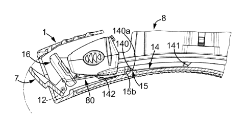
This control profile 14 comprises a recess 140,
close to the back end 141, said recess having a stop face
140b and a slope wall 140a, cooperating with the center
portion 81 of the linkage 80.
Besides, the housing comprises in the bottom shell
CA 02720780 2010-10-06
WO 2009/124600 PCT/EP2008/054445
-16-
member 9 two symmetrical complementary control profiles 15,
shown in figures 3,5 and 11a-lid, having a recess 150
comprising a slide portion 15a and a ramp 15b.
The center portion 81 is sandwiched between the
control profile 14 and the complementary control profiles
as depicted particularly in figures ila to lid.
The movement of the razor head carrier 8,
illustrated in figures 11a-lid, defines a movement stroke S
illustrated in figure 12, comprising a first stroke portion
10 Si in which the control profile 14 pushes or pulls the
center portion 81 of the linkage 80, and a second stroke
portion S2 in which the linkage 80 is not moving and is
located in the recess 150 of the complementary control
profiles 15 (figures ilc, lid).
15 When the sliding mechanism 36 moves from the first
to the second position of the razor head carrier 8, as
illustrated in figure llb, the control profile recess 140
pushes the linkage 80 towards the front end 3 of the razor
handle 1, at least in the first part Si of the stroke
(figures ila and lib), the center portion 81 of the linkage
being retained in the recess 140 by the slide portion 15a
of the complementary control profile 15.
Conversely, when the sliding mechanism moves back
from the second to the first position of the razor head
carrier 8, the control profile recess 140 pulls the linkage
80 towards the back end 4 of the razor handle 1, at least
in the first part S1 of the stroke (figures ila and 11b),
the center portion 81 of the linkage being retained in the
recess 140 by the slide portion 15a of the complementary
control profile 15
As illustrated in figure 12, this first stroke
portion Si of the razor head carrier 8 is less than thirty
percent of the total razor head carrier stroke S. This
first stroke portion S1 corresponds to the opening and
closing of the movable flap 7 (shown as dotted line 7a on
CA 02720780 2010-10-06
WO 2009/124600 PCT/EP2008/054445
-17-
figure llc-lld), while the displacement of the razor head
carrier 8 is relatively small. As a result, the razor head
16 does not touch the movable flap 7 during this part of
the stroke. In other words, the movable flap 7 opens before
the razor head 16 moves out of the opening 5, which
prevents any damage on the razor head 16 or on the cutting
blades themselves.
In the second portion S2 of the stroke, between the
positions shown in figures lic and lid, the center portion
81 of the linkage 80 remains in the recess 150 and the
control profile 14 slides on it without pushing or pulling
it. As the center portion 81 does not move relative to
bottom shell 9, the movable flap 7 remains in the same
position, i.e. fully open. In this position, the flap
member 79 is nearly in contact with the inner surface 95 of
the bottom shell member 9, in line with the bottom shell,
the flap surface 79a being flush with the bottom shell
surface 96. This inner surface 95 constitutes a travel stop
for the flap and the linkage travels.
Along the first stroke portion Sl, the recess 140
receives the center portion 81 of the linkage and moves the
center portion 81 of the linkage along the complementary
control profile 15. Along the second stroke portion S2, the
complementary recess 150 receives the center portion 81 of
the linkage, while the control profile 14 slides and urges
the center portion 81 of the linkage in the complementary
recess 150.
When the razor head carrier 8 is moved from the
first stroke portion Sl to the second stroke portion S2,
the center portion 81 of the linkage is released from the
recess 140 and urged into the complementary recess 150 by
the slope wall 140a. When the razor head carrier 8 is moved
from the second stroke portion S2 to the first stroke
portion Sl, the center portion 81 of the linkage is moved
by the stop face 140b along the ramp 15b from the
CA 02720780 2010-10-06
WO 2009/124600 PCT/EP2008/054445
-18-
complementary recess 150 to the recess 140.
Returning to figure 12, the razor head carrier 8
stroke S presents a rather linear displacement 800 from the
first position Pi to the second position P2. This
displacement 800 is also the displacement of the moving
control profile 14 for the linkage 80.
In the first stroke portion Si, the linkage travel
is proportional to the razor head carrier displacement 800.
The angular displacement of the movable flap (8flap) is
directly linked to the linkage travel through the hinge
12, 13 and the articulation control 83,83b: the flap
angularly moves from the close position 701 to the open
position 702 (corresponding to figure llc).
In the second stroke portion S2, the linkage travel
and the flap angular position (8flap) correspond to the
open position of the flap (as shown in figure llc). In this
portion the razor head carrier 8 can move to its second
position P2 without any mechanical contact between the
razor head 16 and the flap 7. When moving back from the
second position P2 towards the first direction, the razor
head carrier 8 retracts all along the second stroke portion
S2, without any movement on the linkage 80 or on the flap 7
until it reaches the first stroke section, shown by
reference 97. At this point the razor head 16 is nearly
completely retracted. When the retraction movement goes on
towards the position P1, the linkage travel decreases from
702 towards 701 together with the related flap angular
position (8flap).
As a result, all along the stroke S, no contact
occurs between the movable flap 7 and the razor head 16.