Note: Descriptions are shown in the official language in which they were submitted.
CA 02721382 2010-10-14
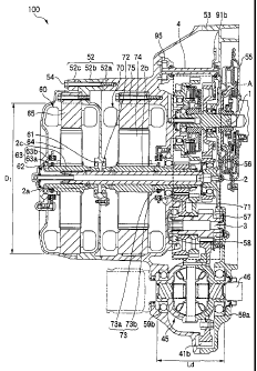
Description
DRIVING APPARATUS FOR HYBRID VEHICLE
TECHNICAL FIELD
[0001]
This invention relates to a driving apparatus for a
hybrid vehicle, and more particularly to a driving apparatus
for a hybrid vehicle including an engine, a motor and a
generator.
BACKGROUND ART
[0002]
As a driving apparatus for a hybrid vehicle including
an engine, a motor and a generator, for example, there is an
apparatus disclosed in Patent Reference 1. In this driving
apparatus for a hybrid vehicle, considering vehicle loading
capability, the engine and generator are arranged coaxially
while the generator and motor are arranged in parallel so that
the entire length of a power transmission system is shortened.
Patent Reference 1: JP-A-8-91065
SUMMARY OF THE INVENTION
PROBLEMS THAT THE INVENTION IS TO SOLVE
[0003]
However, if the engine and generator are arranged
1
CA 02721382 2010-10-14
coaxially as described in Patent Reference 1, the outer
diameter of the generator cannot be increased due to the
limitation of engine merging plane. So, in order to obtain
necessary torque and power, it was necessary to enlarge an axial
dimension. This led to an increase in the axial length, thus
deteriorating the loading capability. Further, since the
generator and motor are arranged in parallel, the outer shape
became bulky in a side view in the figure (axial view) , thereby
deteriorating loading capability.
[0004]
This invention has been accomplished in view of the above
problem, and an object thereof is to provide a driving apparatus
for a hybrid vehicle capable of providing a large generator
outer diameter without suffering from the limitation of the
engine merging plane, thereby shortening the axial length.
MEANS TO SOLVE THE PROBLEM
[0005]
In order to attain the above object, according to an
aspect of the invention, there is provided a driving apparatus
for a hybrid vehicle (e.g. a driving apparatus for a hybrid
vehicle 100 according to an embodiment described later)
includes:
an engine (e.g. an engine 50 in the embodiment);
a first shaft (e. g. an engine shaft 1 in the embodiment)
2
CA 02721382 2010-10-14
which is arranged coaxially with an output shaft (e.g. a crank
shaft 51 in the embodiment) of the engine, and transmits power
from the engine;
a second shaft (e.g. a generator shaft 2 in the
embodiment) arranged in parallel to the first shaft and
including:
an inner shaft (e.g. an inner shaft 2a in the
embodiment) connected to the first shaft through a first
transmission mechanism (e.g. a generator driving gear 10 in
the embodiment) and
a first outer shaft (e. g. a motor-use outer shaft
2b in the embodiment) arranged rotatably relative to the inner
shaft around the inner shaft;
a first motor (e.g. a generator 60 in the embodiment)
connected to the inner shaft;
a second motor (e.g. a motor 70 in the embodiment)
arranged coaxially with the first motor and connected to the
first outer shaft;
a third shaft (e.g. an idler shaft 3 in the embodiment)
arranged in parallel to the second shaft and connected to the
first outer shaft through a second transmission mechanism (e.g.
a motor driving force transmission gear 20 in the embodiment) ;
a differential device (e.g. a differential device 45 in
the embodiment) connected to the third shaft; and
a clutch unit (e.g. a clutch 80 in the embodiment) which
3
CA 02721382 2010-10-14
is arranged on the first shaft, and engages or disengages the
first shaft and the third shaft through a third transmission
mechanism (e.g. an engine driving force transmission gear 30
in the embodiment).
[0006]
According to another aspect of the invention, it is
adaptable that
the first motor is connected to the inner shaft through
a second outer shaft (e.g. a generator-use outer shaft 2c in
the embodiment) provided around the inner shaft and rotatable
together with the inner shaft; and
the first motor and the second motor are supported on
the second outer shaft and the first outer shaft, respectively
by bearings (e.g. bearings 61, 62; 71, 72 in the embodiment)
provided at both ends, respectively.
[0007]
According to still another aspect of the invention, it
is adaptable that
the third transmission mechanism includes a transmitting
section (e.g. an output gear 31a in the embodiment) connected
to the clutch unit and a transmitted section (e.g. an input
gear 31b in the embodiment) connected to the differential
device; and
the clutch unit is provided on the inner side of the
transmitting section.
4
CA 02721382 2010-10-14
[0008]
According to still another aspect of the invention, it
is adaptable that
a transmission mechanism row including the first to third
transmission mechanisms and the clutch unit is housed in a
region of a width Ld of the differential device in the axial
direction.
[0009]
According to still another aspect of the invention, it
is adaptable that
the first motor and the second motor are arranged
adjacently to the transmission mechanism row; and
the outer diameter of the first motor and second motor
is smaller than a maximum outer diameter Dt of the transmission
mechanism row around the second shaft.
[0010]
According to still another aspect of the invention, it
is adaptable that the driving apparatus for the hybrid vehicle,
further including:
a first case (e.g. a first case 52a in the embodiment)
for housing the transmission mechanism row and one end of the
second motor;
a second case (e.g. a second case 52b in the embodiment)
fixed adjacently to the first case, for the one end of the first
motor and the other end of the second motor;
5
CA 02721382 2010-10-14
a third case (e.g. a third case 52c in the embodiment)
fixed adjacently to the second case for housing the other end
of the first motor, wherein
a stator (e.g. a stator 75 in the embodiment) of the second
motor is fixed in the first case, and
a stator (e.g. a stator 65 in the embodiment) of the first
motor is fixed in the second case.
[0011]
According to still another aspect of the invention, it
is adaptable that
the second case is provided with at least two bearings
(e.g. bearings 61, 72 in the embodiment) for supporting the
first outer shaft and the second outer shaft.
[0012]
According to still another aspect of the invention, it
is adaptable that the driving apparatus for the hybrid vehicle,
further including:
a fourth shaft (e. g. an oil pump shaft 4 in the embodiment)
arranged in parallel to the first shaft and connected therewith
through a fourth transmission mechanism (e.g. an oil pump
driving gear 90 in the embodiment),
wherein an oil pump (e. g. an oil pump 95 in the embodiment)
is connected to the fourth shaft.
[0013]
According to still another aspect of the invention, there
6
CA 02721382 2010-10-14
is provided a driving apparatus for a hybrid vehicle (e.g. a
driving apparatus for a hybrid vehicle 200 according to the
embodiment) including:
an engine (e.g. an engine 50 in the embodiment);
a first shaft (e.g. an engine shaft 1 in the embodiment)
which is arranged coaxially with an output shaft (e. g. a crank
shaft 51 in the embodiment) of the engine, and which transmits
power from the engine;
a second shaft (e.g. a generator shaft 2 in the
embodiment) arranged in parallel to the first shaft and
including:
an inner shaft (e.g. an inner shaft 2a in the
embodiment) connected to the first shaft through a first
transmission mechanism (e.g. a generator driving gear 10 in
the embodiment) and
an outer shaft (e.g. an motor-use outer shaft 2b
in the embodiment) arranged around the inner shaft;
a first motor (e.g. a generator 60 in the embodiment)
connected to the inner shaft;
a second motor (e.g. a motor 70 in the embodiment)
arranged on the same axial line as the first motor and connected
to the outer shaft;
a third shaft (e.g. an idler shaft 3 in the embodiment)
arranged in parallel to the second shaft and connected to the
outer shaft through a second transmission mechanism (e.g. a
7
CA 02721382 2010-10-14
motor driving force transmission gear 20 in the embodiment);
and
a differential device (e.g. a differential device 45 in
the embodiment) connected to the third shaft.
[0014]
According to still another aspect of the invention, it
is adaptable that the transmitting section of the third
transmission mechanism is supported in the first case through
a four-point contact ball bearing (e.g. a bearing 88 in the
embodiment).
EFFECTS OF THE INVENTION
[0015]
In accordance with the aspect of the driving apparatus
for the hybrid vehicle of the invention, the driving by the
engine and the driving by the motor can be used selectively
or simultaneously. Further, since the first motor is arranged
in parallel to the output shaft of the engine, there is no
limitation to the merging plane with the engine so that the
outer diameter of the first motor can be increased. Thus, it
is not necessary to increase the axial length in order to
provide the torque or output of the first motor. By shortening
the axial length, the loading capability can be improved.
Further, by engaging the engine with the first motor through
the first transmission mechanism, the speed ratio between the
8
CA 02721382 2010-10-14
engine and the first motor can be set optionally. Thus, it
is possible to match efficient ranges of the first motor and
the engine at the time of using the first motor and the engine
together as the generator, thereby improving the power
generating efficiency. Further, the first motor and second
motor are arranged coaxially to each other, thus, the size from
side view can be reduced. This leads to an improvement of the
loading capability.
[0016]
Further, in accordance with the driving apparatus for
the hybrid vehicle of the invention, the first motor and second
motor can be individually supported. By individually
supporting them, it is possible to prevent their vibrations
from influencing each other.
[0017]
Further, in accordance with the driving apparatus for
the hybrid vehicle of the invention, the clutch unit is provided
on the inner side of the transmitting section of the third
transmission mechanism so that the space in the inner side of
the third transmission mechanism can be efficiently used,
thereby decreasing the length in the axial direction.
[0018]
Further, in accordance with the driving apparatus for
the hybrid vehicle of the invention, the gears constituting
the transmission mechanism row and the clutch unit are fallen
9
CA 02721382 2010-10-14
within the width Ld of the differential device which is a final
output shaft. Thus, the axial length of the device can be
shortened.
[0019]
Further, in accordance with the driving apparatus for
the hybrid vehicle of the invention, the outer diameter of the
first motor and second motor is smaller than the maximum outer
diameter Dt of the transmission mechanism row around the second
shaft so that the radial length of the entire apparatus can
be reduced.
[0020]
In accordance with the driving apparatus for the hybrid
vehicle of the invention, the stator is fixed in each case so
that the first motor and second motor can be surely held and
protected and the assembling capability can be also improved.
Further, since the second case is commonly used as a case for
the first motor and second motor, the number of components can
be reduced.
[0021]
Further, in accordance with the driving apparatus for
the hybrid vehicle of invention, at least two bearings which
is the bearing supporting the first outer shaft and the bearing
supporting the second outer shaft are provided in the second
case sandwiched between the first case and third case. Thus,
the bearings can be rigidly fixed.
CA 02721382 2010-10-14
[0022]
Further, in accordance with the driving apparatus for
the hybrid vehicle of the invention, the oil pump shaft is
arranged separately from the engine shaft so that the axial
length of the entire apparatus can be restricted.
[0023]
Further, in accordance with the driving apparatus for
the hybrid vehicle of the invention, since the first motor is
arranged in parallel to the output shaft of the engine, there
is no limitation to the merging plane with the engine so that
the outer diameter of the first motor can be increased. Thus,
it is not necessary to increase the axial length in order to
provide the torque or output of the first motor. By shortening
the axial length, the loading capability can be improved.
Further, by engaging the engine with the first motor through
the first transmission mechanism, the speed ratio between the
engine and the first motor can be set optionally. Thus, it
is possible to match respective efficient ranges of the first
motor and the engine at the time of using the first motor and
the engine together as the generator, thereby improving the
power generating efficiency. Further, the first motor and
second motor are arranged coaxially. Thus, the size from side
view can be reduced. This leads to an improvement of the
loading capability.
[0024]
11
CA 02721382 2010-10-14
Further, in accordance with the driving apparatus for
the hybrid vehicle of the invention, it is not necessary to
support the transmitting section of the third transmission
mechanism at two ends by two deep-groove ball bearings. It
is possible to support it at one end by using a single bearing
of a four-point contact ball bearing so that the number of
components can be reduced, thereby shortening the axial length
of the driving apparatus for the hybrid vehicle.
BRIEF DESCRIPTION OF THE DRAWINGS
[0025]
Fig. 1 is a schematic view of a first embodiment of a
driving apparatus for a hybrid vehicle of the invention;
Fig. 2 is a sectional view of a driving apparatus for
a hybrid vehicle of the invention; and a view taken in a B-B
arrow in Fig. 4;
Fig. 3 is an enlarged view of part A in Fig. 2;
Fig. 4 is a view for explaining the relationship in
transmission mechanisms of the driving apparatus for the hybrid
vehicle of Fig. 2; and
Fig. 5 is a schematic view of a second embodiment of a
driving apparatus for a hybrid vehicle of the invention.
DESCRIPTION OF REFERENCE NUMERALS AND SIGNS
[0026]
12
CA 02721382 2010-10-14
1 ... engine shaft (first shaft), 2 ... generator shaft (second
shaft), 2a ... inner shaft, 2b ... motor-use outer shaft (first
outer shaft), 2c ... generator use outer shaft (second outer
shaft) , 3 ... idler shaft (third shaft), 4 ... oil pump shaft (fourth
shaft) , 10 ... generator driving gear (first transmission
mechanism) , lla ... output gear, lib ... input gear, 12 ... bearing,
13 ... bearing, 20 ... motor driving transmission gear (second
transmission mechanism) , 21a ... output gear, 21b ... input gear,
30 ... engine driving force transmission gear (third transmission
mechanism), 31a ... transmission gear (transmission section),
31b ... input gear (transmitted section), 40 ... final gear, 41a
... output gear, 41b ... input gear, 45 ... differential device
(differential gear), 46 ... differential shaft, 47 ... driving
wheel, 50 ... engine, 51 ... crank shaft, 52 ... driving device case,
52a ... first case, 52b ... second case, 52c ... third case, 53 ...
damper housing, 54 ... bolt, 55 ... driving plate, 56 ... damper,
57 ... bearing, 58 ... bearing, 59a ... bearing, 59b ... bearing, 60
... generator (first motor), 61 ... bearing, 62 ... bearing, 63 ...
resolver, 63a ... resolver rotor, 63b ... resolver stator, 64 ...
rotor, 65 ... stator, 70 ... motor (second motor), 71 ... bearing,
72 ... bearing, 73 ... resolver, 73a ... resolver rotor, 73b ... resolver
stator, 80 ... clutch (clutch unit) , 81 ... clutch disk, 82 ... clutch
plate, 83 ... clutch piston, 84 ... first clutch holding member,
85 ... outer hub, 86 ... second clutch holding member, 87 ... inner
hub, 88 ... bearing (four-point contact ball bearing), 89 ...
13
CA 02721382 2010-10-14
stopper, 90 ... oil pump driving gear, 91a ... output gear, 91b
... input gear, 95 ... oil pump, 97 ... operating room, and 100, 200
... driving apparatus for a hybrid vehicle.
DESCRIPTION OF THE PREFERRED EMBODIMENTS
[0027]
Hereinafter, referring to the drawings, a detailed
explanation will be given of a driving apparatus for a hybrid
vehicle of the invention. Fig. 1 is a schematic view of a first
embodiment of a driving apparatus for a hybrid vehicle of the
invention. Fig. 2 is a sectional view of a driving apparatus
for a hybrid vehicle of the invention. Fig. 3 is an enlarged
view of part A in Fig. 2. Fig. 4 is a view for explaining the
relationship in a transmission mechanism of the driving
apparatus for the hybrid vehicle of Fig. 2.
[0028]
As shown in Fig. 1, a driving apparatus for a hybrid
vehicle 100 of the invention includes an engine shaft 1 (first
shaft), a generator shaft 2 (second shaft) and an idler shaft
3 (third shaft), which are arranged in parallel.
The generator shaft 2 includes at least an inner shaft
2a and a hollow outer shaft 2b (first outer shaft) which is
attached rotatably relative to the inner shaft 2a.
The engine shaft 1 connected to a crank shaft 51 of an
engine 50 is engaged, through a generator driving gear 10 (first
14
CA 02721382 2010-10-14
transmission mechanism), to the inner shaft 2a of the generator
shaft 2 which is provided with a generator 60 (first motor)
on an axial line of the engine shaft 1. The outer shaft 2b
of the generator shaft 2 which is provided with a motor 70
(second motor) on its axial line is engaged to the idler shaft
3 through a motor driving force transmission gear 20 (second
transmission mechanism) . The engine shaft 1 and idler shaft
3 are engaged to each other through an engine driving force
transmission gear 30 (third transmission mechanism).
The idler shaft 3 and a differential device 45
(differential gear) are engaged to each other through a final
gear 40. The differential device 45 is connected to driving
wheels 47, 47 through a differential axels 46.
The engine shaft 1 is provided with a clutch 80
(engage-disengage means) which serves to engage or disengage
the power between the engine shaft 1 and idler shaft 3 through
the engine driving force transmission gear 30.
[0029]
The driving apparatus for the hybrid vehicle 100 having
these components as main components has a transmission path
which transmits the driving force of the motor 70 to the driving
wheels 47, 47 to travel the vehicle and another transmission
path which transmits the driving force of the engine 50 to the
driving wheels 47, 47 to travel the vehicle, and uses
selectively or simultaneously these two transmission paths to
CA 02721382 2010-10-14
travel the vehicle.
[0030]
First, referring to Fig. 1, an explanation will be given
of the transmission path which transmits the driving force of
the motor 70 to the driving wheels 47, 47 to travel the vehicle.
The engine driving force inputted to the inner shaft 2a
of the generator shaft 2 from the engine shaft 1 through the
generator driving gear 10 rotates the inner shaft 2a of the
generator shaft 2. Thereby, the generator 60 fixed to the inner
shaft 2a of the generator 2 rotates together with the generator
shaft 2 to generate electric power. By using the electric power
generated by the generator 60, the motor 70 connected to the
outer shaft 2b which is arranged rotatably relative to the inner
shaft 2a of the generator shaft 2 rotates the outer shaft 2b
of the generator shaft 2. Then, the motor 70 transmits its
driving force to the idler shaft 3 through the motor driving
force transmission gear 20. The driving force thus
transmitted is transmitted to the driving wheels 47, 47 through
the final gear 40, differential device 45 and differential
axels 46. Thus, the entire driving force of the engine 50 is
changed into electricity by the generator 60, thereby realizing
"series running".
[0031]
On the other hand, in the transmission path which
transmits the driving force of the engine 50 to the driving
16
CA 02721382 2010-10-14
wheels 47, 47 to travel the vehicle, by engaging the clutch
80 attached to the engine shaft 1, the driving force of the
engine shaft 1 is transmitted to the idler shaft 3 through the
transmission gear 30. The driving force thus transmitted is
transmitted to the driving wheels 47, 47 through the final gear
40, differential device 45 and differential axels 46.
In this case, the engine shaft 1 and inner shaft 2a of
the generator shaft 2 are always engaged to each other through
the generator driving gear 10 so that the generator 60 is caused
to generate electric power which rotates the motor 70. This
enables "parallel running" using both machinery and
electricity. Further, by executing "zero torque control" on
the motor 70 and generator 60, dragging loss is minimized so
that the vehicle can traveled using only the engine 50.
[0032]
Referring to Figs. 2 to 4, a concrete explanation will
be given of the structure of a driving apparatus for a hybrid
vehicle 100 of the invention.
The driving apparatus for the hybrid vehicle 100 of the
invention is housed, from the engine 50 side, in a driving
apparatus case 52 having first, second and third cases 52a,
52b and 52c. The first case 52a is fixed to a damper housing
53 for housing a damper 56. The first, second and third cases
52a, 52b and 52c are connected to one another by a plurality
of bolts 54. Within the driving apparatus case 52, the engine
17
CA 02721382 2010-10-14
shaft 1, generator shaft 2 and idler shaft 3 are arranged in
parallel to one another.
[0033]
The engine shaft 1 is arranged coaxially with the crank
shaft 51 of the engine 50. The engine 50 side of the engine
shaft 1 is supported in the damper housing 53 by a bearing 12,
and its opposite side is supported in the first case 52a by
a bearing 13. The driving force of the crank shaft 51 is
transmitted to the engine shaft 1 through a drive plate 55 and
the damper 56. On the engine shaft 1, at its central position
in the axial direction, an output gear lla constituting the
generator driving gear 10 is provided; and on the side opposite
to the engine 50 with respect to the output gear lla, the clutch
80 is provided. Adjacently to the output gear lla, on the
engine 50 side of the output gear lla, an output gear 91a
constituting an oil pump driving gear 90 is integrally
provided.
[0034]
The clutch 80 is a "multi-plate clutch" which includes
a plurality of disk-shaped clutch disks 81 and clutch plates
82 and a clutch piston 83 for urging these clutch disks 81 and
clutch plates 82. The plurality of clutch disks 81 are held
at their outer periphery by a cylindrical outer hub 85 provided
at the outer edge of a first clutch holding member 84 and are
movable in the axial direction. The plurality of clutch plates
18
CA 02721382 2010-10-14
82 are held at their inner periphery by a cylindrical inner
hub 87 fixed to a second clutch holding member 86 and are movable
in the axial direction. Further, the clutch disks 81 and clutch
plates 82 are arranged in parallel to each other and alternately
superposed apart from one another in the axial direction.
[0035]
An output gear 31a constituting the engine driving force
transmission gear 30 is integrally rotatably attached to the
outer edge of the second clutch holding member 86. Further,
the second clutch holding member 86 is supported, at its base
inner face, in the first case 52a by a bearing 88. Here, the
bearing 88 is a four-contact ball bearing and this bearing 88
supports only one end of the second clutch holding member 86
in the first case 52a.
[0036]
The clutch 80 thus structured severs to permit the clutch
disks 81 and clutch plates 82 to contact with or separate from
each other by controlling the oil pressure in an operating room
97. Specifically, when the pressure in the operating room 97
decreases to a predetermined value, a clutch piston 83 moves
to the engine 50 side. The adjacent clutch disk 81 and clutch
plate 82 are separated so that the clutch 80 is disengaged.
At this time, the driving force of the engine shaft 1 will not
be transmitted to the engine driving force transmission gear
30 through the clutch 80.
19
CA 02721382 2010-10-14
[0037]
On the other hand, when pressure in the operating room
97 is increased so as to be higher than the predetermined value,
the clutch piston 83 moves opposite side of to the engine 50.
Thus, the clutch piston 83 urges the clutch disks 81 and clutch
plates 82 to move toward the side opposite to the engine 50,
thereby sandwiching these clutch disks 81 and clutch plates
82 between itself and a stopper 89 fixed to the outer hub 85.
Thus, the adjacent clutch disk 81 and clutch plate 82 are
friction-engaged to engage the clutch 80 so that the second
clutch holding member 86 is directly engaged to the engine shaft
1 so as to be locked up. At this time, since the output gear
31a constituting the generator driving gear 10 is attached to
the second clutch holding member 86, the driving force of the
engine shaft 1 is transmitted to the idler shaft 3 through the
engine driving force transmission gear 30 by the clutch 80.
It should be noted that the driving force of the engine shaft
1 is also transmitted to the generator shaft 2 through the
generator driving gear 10.
[0038]
The generator shaft 2 is arranged in parallel to the
engine shaft 1 and includes an inner shaft 2a, and a motor-use
outer shaft 2b (first outer shaft) and a generator-use outer
shaft 2c (second outer shaft), which are arranged around the
inner shaft 2a. Specifically, on the inner shaft 2a, an input
CA 02721382 2010-10-14
gear lib to be tooth-engaged with the output gear lla of the
generator driving gear 10 of the engine shaft 1 is provided
at its engine side end. Further, on the inner shaft 2a,
the motor-use outer shaft 2b is attached rotatably relative
to the inner shaft 2a at its nearly central position of the
inner shaft 2a. Furthermore, on the inner shaft 2a, the
generator-use outer shaft 2c, which is spline-connected to the
end opposite to the engine 50 of the inner shaft 2a and rotates
together with the inner shaft 2a, is attached adjacently to
the motor-use outer shaft 2b.
[0039]
The generator-use outer shaft 2c is attached with the
generator 60 which is integrally rotatable, and supported in
the second case 52b by a bearing 61 at the end of the engine
50 side and in the third case 52c by a bearing 62 at the end
of the side opposite to the engine 50. Further, between the
bearing 62 and generator 60, a resolver rotor 63a of a resolver
63 for detecting the rotating angle of the generator-use outer
shaft 2c is attached to the generator-use outer shaft 2c and
a resolver stator 63b is attached at the opposite position.
[0040]
The generator 60 includes a rotor 64 with its inner side
end fixed to the generator-use outer shaft 2c and a stator 65
fixed in the second case 52c and arranged oppositely to the
rotor 64. Because of such a structure, the driving force of
21
CA 02721382 2010-10-14
the engine shaft 1 is transmitted to the inner shaft 2a of the
generator shaft 2 through the generator driving gear 10 so that
the rotor 64 of the generator 60 is rotated through the
generator-use outer shaft 2c from the inner shaft 2a. Thus,
the driving force of the engine shaft 1 can be transformed into
electric power.
[0041]
Onto the motor-use outer shaft 2b, the motor 70 which
is integrally rotatable is attached and the output gear 21a
constituting the motor driving force transmission gear 20 is
attached at its engine 50 side end. Further, the motor-use
outer shaft 2b is arranged between the motor 70 and the output
gear 21a, and supported in the first case 52a by a bearing 71
and in the second case 52b by a bearing 72 at the end on the
side opposite to the engine 50. Further, between the bearing
71 and motor 70, a resolver rotor 73a of a resolver 73 for
detecting the rotating angle of the motor-use outer shaft 2b
is attached to the motor-use outer shaft 2b and a resolver
stator 73b is attached at the opposite position.
[0042]
The motor 70 includes a rotor 74 with its inner side end
fixed to the motor-use outer shaft 2b and a stator 75 fixed
in the first case 52a and arranged oppositely to the rotor 74.
[0043]
The idler shaft 3 is arranged in parallel to the generator
22
CA 02721382 2010-10-14
shaft 2, and includes, sequentially from the engine 50 side,
an output gear 41a constituting the final gear 40, an input
gear 31b tooth-engaged with the output gear 31a of the engine
shaft 1 and constituting the engine driving force transmission
gear 30 and an input gear 21b tooth-engaged with the output
gear 21a of the motor-use outer shaft 2b attached rotatably
relative to the generator shaft 2 and constituting the motor
driving force transmission gear 20. The idler shaft 3 is
supported in the damper housing 53 by a bearing 57 at its engine
50 side end, and supported in the first case 52a by a bearing
58 at the end on.the side opposite to the engine 50.
[0044]
Because of the structure described above, the motor 70
rotates by the electric power supplied from the generator 60
so that the motor-use outer shaft 2b rotates. Further, the
output gear 21a of the motor-use outer shaft 2b is tooth-engaged
with the input gear 21b of the idler shaft 3 so that the driving
force of the motor 70 is transmitted to the idler shaft 3.
Further, the output gear 31a of the engine shaft 1
constituting the engine driving force transmission gear 30 is
tooth-engaged with the input gear 31b of the idler shaft 3 so
that during the clutch 80 being engaged, the driving force of
the engine shaft 1 is transmitted to the idler shaft 3.
[0045]
The differential device 45 has a differential axels 46
23
CA 02721382 2010-10-14
arranged in parallel to the idler shaft 3, and is supported
in the damper housing 53 by a bearing 59a at the end of the
engine 50 side and supported in the first case 52a by a bearing
59b at the end of the side opposite to the engine 50. The
differential device 45 has an input gear 41b constituting the
final gear 40 which is tooth-engaged with the output gear 41a
of the idler shaft 3 so that the driving force of the motor
70 inputted to the idler shaft 3 and/or the driving force of
the engine 50 are transmitted to the differential axels 46 and
further transmitted to the driving wheels 47, 47 via the
differential axels 46.
[0046]
In the driving apparatus for the hybrid vehicle 100
constructed as described above, a transmission mechanism row
consisting of the generator driving force transmission gear
10, motor driving force transmission gear 20 and engine driving
force transmission gear 30, as seen from Fig. 2, are housed
within a region with an axial length (width) Ld of the
differential device 45. Further, the outer diameter Dl of the
generator 60 and motor 70 coaxially arranged on the generator
shaft 2, as seen from Fig. 4, is smaller than the maximum outer
diameter Dt of the transmission mechanism row around the
generator shaft 2.
[0047]
Further, an output gear 91a constituting an oil pump
24
CA 02721382 2010-10-14
driving gear 90 (fourth transmission mechanism) fixed to the
engine shaft 1 is tooth-engaged with an input gear 91b of an
oil pump shaft 4 (fourth shaft) arranged in parallel to the
engine shaft 1 thereby to transmit the driving force of the
engine shaft 1 to an oil pump 95. The oil pump 95
pressure-supplies the oil for generating the operating oil
pressure of the clutch 80 and for lubricating and cooling the
respective components.
[0048]
The third case 52c externally covering the generator 60
attached to the second case 52b is attached with the resolver
stator 63b at the position opposite to the resolver 63a attached
to the generator-use outer shaft 2c. The resolver 63 is
arranged to be wrapped on the inner side of the coil end opposite
to the engine 50 of the stator 65 of the generator 60.
[0049]
As understood from the description hitherto made, in
accordance with the driving apparatus for the hybrid vehicle
100 of the invention, by engaging or disengaging the clutch
80, selectively or simultaneously using the transmission path
from the engine 50 and the transmission path from the motor
70, the driving can be done. Further, since the generator 60
is arranged in parallel to the crank shaft 51 of the engine
50, there is no limitation to the merging plane with the engine
50 so that the outer diameter of the generator 60 can be
CA 02721382 2010-10-14
increased according to the specification required. Further,
it is not necessary to increase the axial length in order to
provide the torque or output of the generator 60. Thus, the
axial length of the entire driving apparatus for a hybrid
vehicle 100 can be shortened, thereby giving excellent loading
capability. Further, by connecting the engine 50 with the
generator 60 through the generator driving gear 10, the speed
ratio between the engine 50 and the generator 60 can be set
optionally so that the engine is matched with an efficient
region of the generator 60, thereby improving the power
generating efficiency. Further, since the generator 60 and
motor 70 are arranged on the same axial line, the generator
60 which is relatively large in the radial length and the motor
70 can be superposed in the axial direction. Thus, the
dimension viewed from side in the figure (axial direction) is
shortened. This leads to an improvement of the loading
capability.
[0050]
Further, in accordance with the driving apparatus for
the hybrid vehicle 100 of the invention, with the generator
shaft 2 being made hollow, the motor-use outer shaft 2b and
generator-use outer shaft 2c are provided on the outside of
the inner shaft 2a, and they are supported by the bearings 71,
72; 61, 62 at their ends, respectively. For this reason, the
motor 70 and generator 60 can be supported individually,
26
CA 02721382 2010-10-14
thereby preventing their vibrations from influencing each
other.
[0051]
Further, in accordance with the driving apparatus for
the hybrid vehicle 100 of the invention, the engine driving
force transmission gear 30 is engaged to the clutch 80 on the
one side and engaged to the differential device 45 on the other
side, and the clutch 80 is arranged on the inner side of the
output gear 31a. For this reason, the space between the engine
shaft 1 and output gear 31a can be efficiently used, thereby
decreasing the length in the axial direction.
[0052]
Further, in accordance with the driving apparatus for
the hybrid vehicle 100 of the invention, the transmission
mechanism row consisting of the generator driving force
transmission gear 10, motor driving force transmission gear
and engine driving force transmission gear 30 is housed
within the region of the width (axial length) Ld of the
differential device 45 so that it is fallen within the width
20 of the differential device 45 having a final output shaft of
the transmission mechanism row, thereby shortening the axial
length of the transmission mechanism row. Thus, the axial
length of the entire driving apparatus for a hybrid vehicle
100 can be decreased and the transmission loss can be also
reduced.
27
CA 02721382 2010-10-14
[0053]
Further, in accordance with the driving apparatus for
the hybrid vehicle 100 of the invention, the outer diameter
Dl of the generator 60 and motor 70 coaxially arranged on the
generator shaft 2 is smaller than the maximum outer diameter
Dt of the transmission mechanism row around the generator shaft
2 so that the entire driving apparatus for a hybrid vehicle
100 can be downsized.
[0054]
In accordance with the driving apparatus for the hybrid
vehicle 100 of the invention, the stator 75 of the motor 70
is fixed in the first case 52a and the stator 65 of the generator
60 is fixed in the second case 52b. In this way, by fixing
each of the stators 75, 65 in each of the cases 52a, 52b, the
generator 60 and motor 70 can be surely held and protected and
the assembling capability can be also improved. Further,
since the second case 52b is commonly used as a case for the
generator 60 and motor 70, the number of components can be
reduced.
[0055]
In accordance with the driving apparatus for the hybrid
vehicle 100 of the invention, arranged in the second case 52b
are at least two bearings 72, 61 of the bearing 72 supporting
the motor-use outer shaft 2b at the side opposite to the engine
50 and the bearing 61 supporting the generator-use outer shaft
28
CA 02721382 2010-10-14
2c at the engine 50 side. For this reason, these bearings 72,
61 can be rigidly fixed in the second case 52b firmly sandwiched
between the first and third cases 52a and 52c.
[0056]
In accordance with the driving apparatus for the hybrid
vehicle 100 of the invention, the oil pump shaft 4 is arranged
separately from the engine shaft 1, the axial length can be
restricted.
[0057]
In accordance with the driving apparatus for the hybrid
vehicle 100 of the invention, only one end of the second clutch
holding member 86 provided with the output gear 31a of the
engine driving force transmission gear 30 is supported in the
first case 52a through the bearing 88 of a four-point contact
ball bearing. Thus, as compared with the case where both ends
of the second clutch holding member 86 are supported by two
deep-groove ball bearings, the number of components can be
reduced and the axial length of the driving apparatus for the
hybrid vehicle 100 can be shortened.
[0058]
Additionally, the driving apparatus for the hybrid
vehicle 100 described above which is a first embodiment of this
invention has a transmission path which transmits the driving
force of the motor 70 to the driving wheels 47, 47 to travel
the vehicle and another transmission path which transmits the
29
CA 02721382 2012-10-16
driving force of the engine 50 to the driving wheels 47, 47
to travel the vehicle, and uses selectively or
simultaneously these two transmission paths to travel the
vehicle. However, the driving apparatus for the hybrid
vehicle of the invention should not be limited to the above
described embodiment, but may be appropriately modified or
improved. For example, this invention can be also applied
to the driving apparatus for the hybrid vehicle permitting
only "series running".
A driving apparatus for a hybrid vehicle 200 of a
second embodiment of the invention, as seen from Fig. 5,
has the same structure as the driving apparatus for the
hybrid vehicle 100 according to the above described
embodiment except for the clutch 80 and engine driving
force transmission gear 30, thereby permitting only "series
running". In Fig. 5, like reference symbols refer to like
constituent elements in the first embodiment.