Note: Descriptions are shown in the official language in which they were submitted.
CA 02721633 2010-11-29
1
A modular energy storage device for a high voltage electrical
power system
TECHNICAL FIELD
The present invention relates to a modular energy storage device for
a high voltage electrical power system comprising at least one dc
power-source unit enclosed in a container. By a high voltage
electrical power system should be understood an electrical system
within the range of 3 kV and upwards, preferably in the range of 10
kV and upwards. By energy storage device should be understood dc
power source members connected in series to be within the range of
3 kV and upwards. One or more energy storage devices connected in
parallel can for example be connected to the electrical power system
via a power apparatus capable of controlling reactive power and/or
active power. Examples of power apparatus are a power
compensator and an uninterruptible power supply (UPS).
BACKGROUND OF THE INVENTION
Within flexible alternating current transmission systems (FACTS) a
plurality of control apparatus are known. One such FACTS apparatus
is a static compensator (STATCOM). A STATCOM comprises a voltage
source converter (VSC) having an AC side connected to a high
voltage electrical power system and a DC side connected to a
temporary electric power storage means such as capacitors. The
CA 02721633 2010-11-29
2
STATCOM can supply reactive power to or absorb reactive power
from the transmission line.
As opposed to the STATCOM, which only compensate for reactive
power, another concept is to connect a dc power source to a
compact STATCOM, and thus being able to perform active power
compensation. The construction may be used e.g. as a spinning
reserve and for compensating for fluctuating energy levels in the
power system.
Today the dc power source is a high voltage battery. Since the
power apparatus is connected to the ac voltage of the high voltage
electrical power system, a large number of battery cells have to be
connected in series to match the dc voltage of the power apparatus.
Moreover, to obtain a desired amount of electric energy (duration of
active power) of the energy storage, a number of strings including a
plurality of battery cells could be connected in parallel. The first
conductor and the batteries themselves are typically placed at a
distance to the second conductor. Since the conductors often
consists of non-isolated metal bus bars this safe distance is
important to prevent an accidental and contemporaneous contact of
the conductors.
Furthermore, in case of a fault, such as a short-circuit, the power
apparatus has to be protected. Consequently, two switches are
provided in each string to disconnect the string in case the
converter, a string, or a part of the string is short-circuited. One
switch is able to disconnect the string from the positive dc rail of the
CA 02721633 2010-11-29
3
converter and the other switch is able to disconnect the string from
the negative dc rail of the converter. Each of the switches has to be
rated for the entire converter voltage to be capable of protecting the
power apparatus.
Up to now, mechanical dc circuit breakers have been used as
switches for connection and disconnection of the strings. However,
the availability of dc circuit breakers is limited and the ratings of
these breakers are considerably low and less than the required
voltage ratings in high voltage electrical power systems. To overcome
this problem mechanical ac circuit breakers with some additional
circuitry, such as a resonance circuit connected in parallel with the
ac circuit breaker, have been used.
A solid-state switch is an electronic switch that, unlike a mechanical
breaker, contains no moving parts. There is a desire on the market
to be able to exchange the mechanical ac circuit breakers with solid-
state switches as proposed in WO/2009/152849 where solid-state
switches are distributed among the dc power-source units. However,
high voltage power applications require large electric bus bar
constructions that inevitably lead to high loop inductance. The loop
inductance acts as a limiter of the current derivative (di/dt) during
switching transitions. Since the turn-off of solid-state switches is
much faster than the turn-off of mechanical breakers, large loop
inductance implies high energy storage in the electric bus bar
constructions and during fast interruption this energy will appear as
a voltage spike across the switch (see equation 1 & 2). This voltage
spike will have fatal effects and destroy the switches.
CA 02721633 2010-11-29
4
1
EL =2LI2
1
Vsw,tch = L . dt (2)
A known solution to reduce high voltage spikes across circuit
breakers is to use additional equipment such as different kinds of
snubber circuits and varistors connected to the breaker. Such
additional equipment is however costly.
SUMMARY OF THE INVENTION
It is an object of the invention to overcome or at least alleviate the
above-mentioned problems. In particular, it is an object of the
invention to provide an improved energy storage device for a high
voltage electrical power system.
According to one aspect of the invention this object is achieved by a
modular energy storage device as defined in claim 1.
The modular energy storage device for a high voltage electrical
power system according to the invention is characterized in that it
comprises at least two modules connected in series, each module
including at least one dc power-source unit enclosed in a container
and a positive and a negative terminal, and the device further
comprising a positive and a negative pole, a first and a second
conductor arranged to form a current path between the positive and
negative poles, the first conductor including a plurality of conductor
CA 02721633 2010-11-29
parts connected to the terminals of the modules to provide a series
connection of the modules, a first module of the series connection of
the modules being connected to one of the poles, and the second
conductor is connected between a last module in the series
5 connection of modules and the other pole, wherein the first and
second conductors are arranged to pass through the containers in
parallel such that a current flows through the first conductor in a
first direction and through the second conductor in a second
direction opposite to the first direction.
An advantage with the modular energy storage device according to
the invention is that by arranging the first and second conductor to
pass through the containers in parallel, the distance between the
conductors will be reduced leading to a reduced loop inductance and
hence a reduced voltage spike will appear across the switch when
the energy storage device is disconnected (see equation 2). As a
result the rating of the disconnecting solid-state switch can be
reduced. A further advantage is a minimised need for snubber
circuits and varistors, the ratings of which at least can be
significantly decreased. Additional advantages are that the energy
storage device is compact, modular and has a flexible design.
With a dc power-source unit is meant a plurality of series- and/or
parallel-connected dc power source members. With a dc power
source member is meant a small entity capable of providing dc
power, such as a battery cell, a photovoltaic cell, a fuel cell, a
flywheel or a super capacitor. Different types of dc power source
members could also be combined in the dc power source.
CA 02721633 2010-11-29
6
In an embodiment of the invention, at least one of the conductors
comprises an insulated cable. An advantage with the use of an
insulated cable is that electrical insulation of the conductor is
automatically achieved. Hence the conductors can be placed with a
very short distance to each other or even surface to surface in order
to minimise the loop inductance of the energy storage device.
Additionally, the insulation between the conductor and the container
will be improved. A further advantage is that the degree of safety
increases since the cable insulation prevents a person from having
accidental contact with the conductor.
In an embodiment of the invention both conductors comprise an
insulated cable. An advantage with the use of insulated cables is
that electrical insulation of the conductors is automatically achieved.
Hence the conductors can be placed with a very short distance to
each other or even surface to surface in order to minimise the loop
inductance of the energy storage device. Moreover, the insulation
between the conductors and the container will be improved. An
additional advantage is that less isolation is required when both the
conductors comprise an isolated cable.
In an embodiment of the invention the first conductor comprises a
metal tube, in the following denoted tube, surrounding the second
conductor. For example, the second conductor is a cable. An
advantage with this embodiment is that the loop inductance will be
even smaller compared with parallel conductors. Accordingly, the
snubber circuit ratings, the varistor ratings and the solid-state
CA 02721633 2010-11-29
7
switch ratings can be further reduced. This embodiment also
minimises the risk of module short-circuits due to the fact that the
second conductor is enclosed by the first conductor. This solution
also provides for an easy installation procedure where a standard
insulated high voltage cable easily can be pushed through the tube
to form the return path of the current.
In an embodiment of the invention the second conductor comprises
a second tube arranged with the envelope surface at a distance from
the tube of the first conductor such that an electrical isolation is
achieved between the tubes. One advantage with this embodiment is
that the copper utilization is minimised.
In an embodiment, each module provides DC voltage at 1-10 kV,
preferably between 2 and 5 kV or approximately 3 kV. The energy
storage device can be dimensioned for voltages between 10 kV and
100 kV, or even more than 100 kV. In an embodiment each battery
unit provides between 50 and 1000 volts, such as more than 100
volts and/or lower than 500 volts, especially between 150 and 350
volts or approximately 250 volts. Twelve 250-volt battery units
create a module voltage of 3 kV. Each module includes preferably
more than three battery units, such as more than five or seven
units, or more than ten units, such as twelve battery units or more.
In an embodiment of the invention the distance between the
envelope surfaces of the first and second conductor does not exceed
20 cm.
CA 02721633 2010-11-29
8
One or more energy storage devices connected in parallel can for
example be connected to the electrical power system via a power
apparatus capable of controlling reactive power and/or active power.
Examples of power apparatus are a power compensator and an
uninterruptible power supply (UPS).
BRIEF DESCRIPTION OF THE DRAWINGS
The present invention will be more fully described by way of
example with reference to the accompanying drawings in which:
Figure 1 shows a schematic figure of a first embodiment in
accordance with the invention,
Figure 2 shows a schematic figure of a second embodiment in
accordance with the invention,
Figure 3 shows a first and second conductor of the second
embodiment in more detail.
DETAILED DESCRIPTION OF THE INVENTION
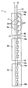
Figure 1 shows a modular energy storage device 1 for a high voltage
electrical power system according to a first embodiment of the
invention. High voltage electrical power systems can be networks for
transmission or distribution of electrical energy as well as industries,
hospitals and such. The same reference numerals are used
throughout the figures for same or corresponding parts. The modular
energy storage device includes two or more modules connected in
series. The storage device 1 shown in figure 1 has three modules
CA 02721633 2010-11-29
9
3a-c. However, the number of module can be less or more than
three. Each module 3a-c includes at least one dc power-source unit
enclosed in a container 7 and a positive 9a 10a and a negative 9b
10b terminal. The number of dc power-source units may vary. The
5 device 1 further includes a positive 12 and a negative 11 pole, a first
conductor 14 in the form of an insulated cable including a plurality of
insulated cable parts 15a-c connected to the terminals 9a-b 10a-b of
the modules 3a-c to provide a series connection of the modules
3a-c, and a second conductor 17 in the form of an insulated cable
connected to the negative terminal 10b of the last module 3c in the
series connection of modules 3a-c. Alternatively, the second
conductor 17 can be connected to the positive terminal 9a of the
first module 3a in the series connection of modules 3a-c. Series
equipment devices such as switches (not shown) and dc power-
source units 5 are connected in series with conductor parts 23 in the
form of insulated cables thereby closing a current path between the
positive 12 and negative 11 pole through the first 14 and second
insulated cable 17. The first 14 and second 17 insulated cables are
arranged to pass through the containers 7 in parallel such that a
current flows through the first insulated cable 14 in a first direction
and through the second insulated cable 17 in a second direction
opposite to the first direction. High voltage insulated cables are
suitable for this purpose.
Figure 2 shows a modular energy storage device 40 for a high
voltage electrical power system according to a second embodiment
of the invention. The storage device 40 includes a first conductor 30
in the form of a conducting tube 30 which comprises a plurality of
CA 02721633 2010-11-29
tube parts 16a-c connected to the terminals 9a-b 10a-b of the
modules 4a-c to provide a series connection of the modules 4a-c,
and a second conductor 17 connected to the negative terminal 10b
of the last module 4c in the series connection of modules 4a-c.
5 Alternatively, the second conductor 17 can be connected to the
positive terminal 9a of the first module 3a in the series connection of
modules 4a-c. The second conductor 17 is enclosed in the first
conductor 30. The first tube 30 further comprises a plurality of tube
parts 6 which interconnects the series equipment devices such as
10 switches (not shown) and the dc power source units 5 thereby
closing a current path between the positive 12 and negative 11 pole
through the first 30 and second conductor 17. The first tube 30 and
second conductor 17 are arranged to pass through the containers 7
in parallel such that a current flows through the first tube 30 in a
first direction and through the second conductor 17 in a second
direction opposite to the first direction. The second conductor 17
includes in one embodiment a metal tube. Suitable material for the
tubes are copper, aluminium or the like. In another embodiment the
second conductor 17 includes an insulated cable.
Figure 3 shows a part of the first tube 30 and the second conductor
17 which is enclosed in the first tube 30. The figure shows the tube
part 16a which connects the first module 4a to the positive pole (not
shown in figure 3) and the tube part 16b which connects the first
module 4a to the second module 4b. Between said tube parts 16a-b
another tube part 6 is shown. This tube part 6 interconnects the
series equipment devices such as switches and dc power source
units 5 (not shown in figure 3) thereby closing the current path of
CA 02721633 2010-11-29
11
the energy storage device. There may be several tube parts 6
depending on the number of series equipment devices. Tap-off
devices 22a-b are used to connect the series equipment devices to
the first tube 30. Between the two corresponding tap-off devices
22a-b an insulating spacer 20 of a non-conducting material is placed
in order to not short-circuit the series equipment device. The series-
connection of two modules is achieved by a connector 21 of a
conducting material such as copper or aluminium. Accordingly, the
tube part 16b which connects the first 4a and second 4b modules
includes two tube parts 33-34 and the connector 21. In one
embodiment the second conductor 17 is a metal tube and in another
embodiment the second conductor 17 is a an insulated cable.