Language selection

Search

Patent 2721725 Summary

Third-party information liability

Some of the information on this Web page has been provided by external sources. The Government of Canada is not responsible for the accuracy, reliability or currency of the information supplied by external sources. Users wishing to rely upon this information should consult directly with the source of the information. Content provided by external sources is not subject to official languages, privacy and accessibility requirements.

Claims and Abstract availability

Any discrepancies in the text and image of the Claims and Abstract are due to differing posting times. Text of the Claims and Abstract are posted:

  • At the time the application is open to public inspection;
  • At the time of issue of the patent (grant).
(12) Patent: (11) CA 2721725
(54) English Title: VEHICLE TRACK
(54) French Title: CHENILLE POUR VEHICULE
Status: Granted
Bibliographic Data
(51) International Patent Classification (IPC):
  • B62D 55/24 (2006.01)
(72) Inventors :
  • WELLMAN, RONALD ALAN (United States of America)
(73) Owners :
  • CONTITECH USA, INC. (United States of America)
(71) Applicants :
  • VEYANCE TECHNOLOGIES, INC. (United States of America)
(74) Agent: PERRY + CURRIER
(74) Associate agent:
(45) Issued: 2017-01-17
(22) Filed Date: 2010-11-19
(41) Open to Public Inspection: 2011-05-25
Examination requested: 2014-11-19
Availability of licence: N/A
(25) Language of filing: English

Patent Cooperation Treaty (PCT): No

(30) Application Priority Data:
Application No. Country/Territory Date
61/264,535 United States of America 2009-11-25

Abstracts

English Abstract


The tracks of the present invention utilize cut pieces of reinforcement which
are associated with
each individual drive lug. By using individual pieces the lugs can be easily
built up with multiple
layers of rubber and reinforcement. Incorporation of such inner fabric
reinforcement layers adds
stiffness to the lugs and thereby increases the torque capacity of the track.
All embedded inner
fabric reinforcement layers are made of individually cut pieces of fabric
which do not extend
continuously around the entire circumference of the track. In the
circumferential direction the
fabric layers typically both begin and end within the lug without extending
into the carcass of the
track. In one aspect, the invention is an endless vehicle track comprising a
body formed of an
elastomeric material having an outer surface displaying a series of ground
engaging profiles
longitudinally spaced along said surface and an inner surface displaying a
series of longitudinally
spaced drive lugs adapted to be engaged by drive sprockets on said vehicle for
retaining said
track on said vehicle and for driving said vehicle, said drive lugs having a
given width and
height, said drive lugs having embedded therein at least a first inner fabric
reinforcement layer
extending into the lugs to a distance inward from the outer surface, wherein
the inner fabric
reinforcement layer begin at a first point within the lugs and end at a second
point within the
lugs.


French Abstract

Les chenilles de la présente invention utilisent des morceaux de renfort découpés qui sont associés à chaque patte dentraînement individuelle. En utilisant des morceaux individuels, les pattes peuvent facilement accumuler avec des couches multiples de caoutchouc et de renfort. Lincorporation de telles couches intérieures de renfort en tissu ajoute une rigidité aux pattes et accroît ainsi la capacité de couple de la chenille. Toutes les couches intérieures de renfort en tissu incorporées sont constituées de morceaux de tissu découpés individuellement qui ne sétendent pas en continu autour de toute la circonférence de la chenille. Dans la direction circonférentielle, les couches de tissus commencent et se terminent à la fois dans la patte sans sétendre dans la carcasse de la chenille. Dans un aspect, linvention est une chenille sans fin pour véhicule qui comprend un corps formé dun matériau élastomère avec une surface extérieure qui affiche une série de profils sengageant dans le sol longitudinalement espacés le long de ladite surface et une surface intérieure qui affiche une série de pattes dentraînement espacées longitudinalement conçues pour être mises en prise par des pignons dentraînement sur ledit véhicule pour retenir ladite chenille sur ledit véhicule et pour entraîner ledit véhicule, lesdites pattes dentraînement ayant une largeur et une hauteur données, lesdites pattes dentraînement incorporant au moins une première couche intérieure de renfort en tissu qui sétend dans les pattes à une distance à lintérieur de la surface extérieure, dans laquelle la couche intérieure de renfort en tissu commence à un premier point à lintérieur des pattes et se termine à un second point à lintérieur des pattes.

Claims

Note: Claims are shown in the official language in which they were submitted.


7
WHAT IS CLAIMED IS:
1. An endless vehicle track comprising a body formed of an elastomeric
material having an
,outer surface displaying a series of ground engaging profiles longitudinally
spaced along said
surface and an inner surface displaying a series of longitudinally spaced
guide-drive lugs for
retaining said track on said vehicle and/or driving said vehicle, said guide-
drive lugs having a
given width and height, said guide-drive lugs having embedded therein at least
a first inner fabric
reinforcement layer extending into the guide-drive lugs to a distance inward
from the outer
surface, wherein the inner fabric reinforcement layer begins at a first point
within the guide-drive
lugs and ends at a second point within the guide-drive lugs.
2. The endless vehicle track of claim 1 wherein the inner fabric
reinforcement layer does not
extend continuously and longitudinally between different lugs on the track.
3. The endless vehicle track of claim 1 wherein the inner fabric
reinforcement layer has a
transverse width that is narrower than or equal to the width of the guide-
drive lugs.
4. The endless vehicle track of claim 1 wherein the inner fabric,
reinforcement layer extends
into the lugs from essentially the base of the lugs where the lugs are affixed
to the body of the
track.
5. The endless vehicle track of claim I wherein the inner fabric
reinforcement layer extends
into the lugs from a point that is at least 0.125 inch from the base of the
lugs.
6. The endless vehicle track of claim 1 wherein the inner fabric
reinforcement layer extends
into the lugs from a point that is at least 0.25 inch from the base of the
lugs, and wherein the
inner fabric reinforcement layer is embedded within the lugs at a minimum
distance of 0.25 inch
from an outer surface of an upper face of the guide-drive lugs.
7. The endless vehicle track of claim 5 wherein the inner fabric
reinforcement layer is
embedded within the lugs at a minimum distance of 0.125 inch from an outer
surface of an upper
face of the guide-drive lugs.

8
8. The endless vehicle track of claim 1 which is further comprised of an
outer fabric
reinforcement layer that extends over the lugs at or near the surface of at
least one drive face of
said lugs.
9. The endless vehicle track of claim 8 wherein the outer fabric
reinforcement layer extends
over the lugs at or near the surface of at least one drive face of said lugs
and further extends over
the lugs at or near the surface of at least a portion of the upper face of
said lugs.
10. The endless vehicle track of claim 8 wherein the outer fabric
reinforcement layer extends
over the lugs at or near the surface of the guide-drive lugs and further
extends at or near the
surface of at least a portion of the drive face and the reverse face of the
guide-drive lugs.
11. The endless vehicle track of claim 8 wherein the outer fabric
reinforcement layer extends
at or near the surface of substantially the entire surface of the lugs.
12. The endless vehicle track of claim 1 which is further comprised of a
second inner fabric
reinforcement layer which is embedded in the guide-drive lugs.
13. The endless vehicle track of claim 12 wherein the second inner fabric
reinforcement layer
is embedded at least 0.125 inch deeper into the guide-drive lugs from the
upper face of the guide-
drive lugs than the first inner fabric reinforcement layer.
14. The endless vehicle track of claim 12 wherein the second inner fabric
reinforcement layer
is embedded at least 0. 25 inch deeper into the guide-drive lugs from the
upper face of the guide-
drive lugs than the first inner fabric reinforcement layer.
15. The endless vehicle track of claim 12 which is further comprised of a
third inner fabric
reinforcement layer within the guide-drive lugs, wherein the third inner
fabric reinforcement
layer is embedded at least 0.125 inch deeper into the guide-drive lugs from
the upper face of the
guide-drive lugs than the second inner fabric reinforcement layer.

9
16. The endless vehicle track of claim 15 wherein the third inner fabric
reinforcement layer is
embedded at least 0.25 inch deeper into the guide-drive lugs from the upper
face of the guide-
drive lugs than the second inner fabric reinforcement layer.
17. The endless vehicle track of claim 1 which includes at least 4 inner
fabric reinforcement
layers.
18. The endless vehicle track of claim 1 wherein the inner fabric
reinforcement begins at a
first point within the lugs and-ends at a second point within the lugs without
extending into the
body of the track.
19. The endless vehicle track of claim 8 wherein the outer fabric
reinforcement layer
longitudinally extends continuously from lug to lug.
20. The endless vehicle track of claim 8 wherein the outer fabric
reinforcement layer is non-
continuous with the fabric reinforcement of adjacent lugs overlapping each
other.

Description

Note: Descriptions are shown in the official language in which they were submitted.


CA 02721725 2016-02-26
VEHICLE TRACK
Background of the Invention
Positive drive, endless rubber tracks such as those used on agricultural or
industrial
vehicles typically have an internal, center row of individual drive lugs which
engage drive bars
on a drive wheel. The continued use and contact between the drive bar and
drive lugs cause
internal lug stresses and surface wear at the points of contact. Additionally,
the internal, center
row of lugs are typically functioning not only to transmit power from the
drive wheel to the
track, but also to retain the track on the vehicle. Contact between the
vehicle undercarriage
wheels and lateral end of the guide surfaces of the inner lugs frequently
occurs as the vehicle
maneuvers during normal service. This contact can cause wearing of the inner
lugs, which can be
severe, depending upon various vehicle design features and application use.
Driving and/or
guiding forces on the inner lugs, henceforth referred to as guide-drive lugs,
can lead to cracks
and eventual chunking of the rubber surface, and possibly to complete removal
of the drive lugs,
making the track unserviceable. Thus, a track belt having guide-drive lugs
which are stronger
and more resistant to wear is desired.
United States Patent Publication No. 2008/0136255 Al discloses an endless
track belt for
use in an industrial or agricultural vehicle. The endless rubber track belts
described therein
include a rubber carcass having an inner surface having one or more drive lugs
and an outer
surface having tread lugs. The drive lugs include reinforcement layers that
partially or
substantially cover all or a portion of the end faces of the drive lugs. The
reinforcement layers
may include continuous strips, or discrete strips. The reinforcement layer may
also be fabric
cutouts to match the shape of the drive end faces of the drive lugs.
United States Patent 6,974,196 B2 describes an endless track for an industrial
or

CA 02721725 2010-11-19
- 2 -
agricultural vehicle consisting of a body formed of a rubber material having
an outer surface
displaying a series of ground engaging profiles longitudinally spaced along
the surface and
an inner surface displaying a series of longitudinally spaced drive lugs
adapted to be
engaged by drive sprockets on the vehicle driving assembly. The body of the
endless track
is fabric reinforced. One layer of fabric longitudinally extends at a distance
from the inner
surface of the track and has a width slightly less than the width of the drive
lugs so that the
fabric may extend inside the drive lugs to increase their rigidity.
Summary of the Invention
The tracks of the present invention utilize cut pieces of reinforcement which
are
associated with each individual drive lug. By using individual pieces the lugs
can be easily
built-up with multiple layers of rubber and reinforcement. The cut pieces can
be
strategically shaped and placed to optimize their effect to attain improved
performance and
durability of the track, including higher tractive effort loads.
Incorporation of such fabric reinforcement layers adds stiffness to the lugs
and
thereby increases the torque capacity of the track. Additional layers also
provide increased
damage resistance after the outer layers of fabric are worn away, and added
layers improve
wear resistance on the sides of the lugs due to undercarriage misalignment and
track-to-
wheel contact which is encountered when the vehicle is turned during normal
operations.
All embedded inner fabric reinforcement layers are made of individually cut
pieces
of fabric which do not extend continuously around the entire circumference of
the track.
The finite length of embedded inner fabric reinforcement is as wide as or
narrower than the
width of the lug. In the circumferential direction the inner fabric
reinforcement layers
typically both begin and end within the lug without extending into the carcass
of the track.
In other words, the inner fabric reinforcements do not extend through the base
of the lugs.
In many cases the inner fabric reinforcement layers extend into the lugs from
a point that is
near the base of the lugs but do not normally extend into the carcass of the
track.
In one embodiment of this invention the lugs also include an outer fabric
reinforcement layer which can be as wide, wider, or narrower than the width of
the lugs.
This outer fabric reinforcement layer longitudinally can extend from lug to
lug in a

CA 02721725 2010-11-19
=
- 3 -
continuous manner or can be non-continuous layer which extends partially of
totally through
the lugs. In cases where the outer fabric reinforcement is a discontinuous
layer the
individual pieces can overlap each other from lug to lug.
The present invention more specifically discloses an endless vehicle track
comprising a body formed of an elastomeric material having an outer surface
displaying a
series of ground engaging profiles longitudinally spaced along said surface
and an inner
surface displaying a series of longitudinally spaced guide-drive lugs for
retaining said track
on said vehicle and/or driving said vehicle, said guide-drive lugs having a
given width and
height, said guide-drive lugs having embedded therein at least a first inner
fabric
reinforcement layer extending into the guide-drive lugs to a distance inward
from the outer
surface, wherein the inner fabric reinforcement layer begins at a first point
within the guide-
drive lugs and ends at a second point within the guide-drive lugs.
Brief Description of the Drawings
Figure 1 is an elevation view of an exemplary endless rubber track assembly.
Figure 2 is a perspective view of a section of the exemplary endless rubber
track
shown in Figure 1.
Figure 3 is a cross-sectional view of the endless rubber track of Figure 2,
taken
generally along line 3-3 in Figure 2.
Figure 4 is a cross-sectional view of the endless rubber track of Figure 2,
taken
generally along line 4-4 in Figure 2.
Figure 5 is a cross-sectional view of a drive lug showing a layer of fabric
longitudinally extending into the lugs to a distance inward from the outer
surface, wherein
the fabric reinforcements begin at a first point within the lugs and end at a
second point
within the lugs without extending into the carcass of the track.
Figure 6 is a cross-sectional view of a drive lug showing multiple layers of
fabric
longitudinally extending into the lugs to a distance inward from the outer
surface, wherein
the fabric reinforcements begin at a first point within the lugs and end at a
second point
within the lugs without extending into the carcass of the track.

CA 02721725 2010-11-19
- 4 -
Detailed Description of the Invention
Figure 1 illustrates a track assembly 10 which may be used on an industrial or

agricultural vehicle (not shown). The track assembly 10 includes a drive wheel
12
comprising a plurality of teeth or drive bars 14 that are positioned for
mating engagement
with guide-drive lugs 16. The drive lugs 16 are mounted on a rubber track 20
having an
endless elongate carcass. The endless track carcass has an outer surface 22
comprising a
plurality of ground engaging tread lugs 24 and an inner surface 26 with a
plurality of guide-
drive lugs 16, typically located on the center portion of the carcass.
Figure 2 illustrates one embodiment of this invention wherein the guide-drive
lugs
both retain the track on the vehicle and are engaged by the drive wheel to
transfer power to
the track. In another embodiment of this invention, the guide-drive lugs are
only provided
for the purpose of retaining the track on the vehicle. In this scenario, the
guide-drive lug
only act in the capacity of guide-lugs. In cases where the lugs act to both
guide and drive
the track, each guide-drive lug 16 comprises an elongated shaped bar with
inclined drive
faces 17, 19, and an upper flat face 21. The inclined faces are typically
known as the drive
face 17 and the reverse face 19 of the guide-drive lugs 16. End or guiding
faces 23, 25 may
be flat or in the alternative they can have various other shapes.
As shown in Figure 3 and Figure 4, the belt carcass 20 typically comprises one
or
more layers of gum rubber or elastomeric material 30. Embedded within the gum
rubber are
one or more reinforcement layers 32 which extend transversely along the track
width. The
reinforcement layers 32 may comprise longitudinal cable reinforcement layers,
fabric
reinforcement layers, or any other reinforcement layer known to those skilled
in the art. The
guide-drive lugs 16, as shown in Figures 2-4 are comprised of natural rubber
or synthetic
rubber, such as emulsion styrene-butadiene rubber, solution styrene-butadiene
rubber,
synthetic polyisoprene rubber, polybutadiene rubber, or a blend of natural and
synthetic
rubbers.
Figure 5 shows an inner fabric reinforcement layer 40 embedded within a drive
lug
16 wherein the inner fabric extends into the drive lugs 16 to a distance
inward from the outer
surface (upper flat face 21 of the drive lugs 16), wherein the inner fabric
reinforcement layer
40 begins at a first point within the lugs and end at a second point within
the lugs without

CA 02721725 2010-11-19
- 5 -
extending into the carcass of the track 43. As can be seen, the inner fabric
reinforcement
layer does not extend continuously between different lugs of the track. It
should also be
noted that the inner fabric reinforcement layer has width that is narrower
than or equal to the
width of the drive lugs. In one embodiment of this invention the inner fabric
reinforcement
layer 40 extends into the lugs 16 from a point at or close to the base 46 of
the lugs (as shown
in Figure 5) where the lugs are affixed to the carcass of the track 43. In one
embodiment of
this invention the inner fabric reinforcement layer extends into the lugs from
a point 45 that
is at least 0.125 inch from the base 46 of the lugs 16. The base of the lugs
is also shown as
line 50 in Figure 4. It is typical for the inner fabric reinforcement layer 40
to extend into the
lugs 16 from a point 45 that is at least 0.25 inch from the base 46 of the
lugs 16. The inner
fabric reinforcement layer 40 will typically also be embedded within the lugs
16 at a
distance of at least 0.125 inch from the upper surface 21 (outer surface) of
the lugs. In many
cases the inner fabric reinforcement layer 40 will be embedded within the lugs
16 at a
distance of at least 0.25 inch from the upper surface 21 (outer surface) of
the lugs. In most
cases the inner fabric reinforcement 40 will be embedded totally within the
lugs without
extending beyond the base 46 of the lugs 16 and certainly without extending
into the carcass
43 of the track.
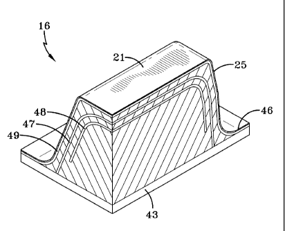
Figure 6 illustrates another embodiment of this invention wherein multiple
layers of
inner fabric reinforcement 47, 48 are included within each drive lug 16 and
extending into
the drive lugs to a distance inward from the outer surface (upper flat face 21
of the drive
lugs 16), wherein the fabric reinforcements begin at a first point within the
lugs and end at a
second point within the lugs without extending into the carcass of the track
43. In the
embodiment of the invention illustrated in Figure 6 an outer (external) fabric
reinforcement
layer 49 is built onto the outer surface of the drive lugs 16. In this
embodiment of the
invention both the first fabric reinforcement layer 47 and the second fabric
reinforcement
layer are embedded within the lugs 16 without extending into the carcass of
the track. The
second inner fabric reinforcement layer 48 will typically embedded at least
0.125 inch
deeper into the drive lugs 16 from the upper face 21 of the drive lugs than
the first inner
fabric layer 47. In most cases, the second inner fabric reinforcement layer 48
will be
embedded at least 0.25 inch deeper into the drive lugs 16 from the upper face
21 of the drive

CA 02721725 2010-11-19
=
- 6 -
lugs than the first inner fabric layer 47. Additional, inner fabric
reinforcement layers will
normally be embedded into the lugs at a distance of at least 0.125 inches and
preferably at
least 0.25 inches apart (deeper into the lug that the next inner fabric
reinforcement layer).
The tracks of this invention can optionally contain 3, 4 or even more layers
of fabric
reinforcement.
While certain representative embodiments and details have been shown for the
purpose of illustrating the subject invention, it will be apparent to those
skilled in this art
that various changes and modifications can be made therein without departing
from the
scope of the subject invention.

Representative Drawing
A single figure which represents the drawing illustrating the invention.
Administrative Status

For a clearer understanding of the status of the application/patent presented on this page, the site Disclaimer , as well as the definitions for Patent , Administrative Status , Maintenance Fee  and Payment History  should be consulted.

Administrative Status

Title Date
Forecasted Issue Date 2017-01-17
(22) Filed 2010-11-19
(41) Open to Public Inspection 2011-05-25
Examination Requested 2014-11-19
(45) Issued 2017-01-17

Abandonment History

There is no abandonment history.

Maintenance Fee

Last Payment of $263.14 was received on 2023-11-15


 Upcoming maintenance fee amounts

Description Date Amount
Next Payment if standard fee 2024-11-19 $347.00
Next Payment if small entity fee 2024-11-19 $125.00

Note : If the full payment has not been received on or before the date indicated, a further fee may be required which may be one of the following

  • the reinstatement fee;
  • the late payment fee; or
  • additional fee to reverse deemed expiry.

Patent fees are adjusted on the 1st of January every year. The amounts above are the current amounts if received by December 31 of the current year.
Please refer to the CIPO Patent Fees web page to see all current fee amounts.

Payment History

Fee Type Anniversary Year Due Date Amount Paid Paid Date
Application Fee $400.00 2010-11-19
Registration of a document - section 124 $100.00 2010-12-06
Maintenance Fee - Application - New Act 2 2012-11-19 $100.00 2012-11-16
Maintenance Fee - Application - New Act 3 2013-11-19 $100.00 2013-11-13
Maintenance Fee - Application - New Act 4 2014-11-19 $100.00 2014-09-23
Request for Examination $800.00 2014-11-19
Maintenance Fee - Application - New Act 5 2015-11-19 $200.00 2015-10-21
Maintenance Fee - Application - New Act 6 2016-11-21 $200.00 2016-10-19
Final Fee $300.00 2016-12-06
Registration of a document - section 124 $100.00 2017-06-30
Maintenance Fee - Patent - New Act 7 2017-11-20 $200.00 2017-11-06
Maintenance Fee - Patent - New Act 8 2018-11-19 $200.00 2018-11-06
Maintenance Fee - Patent - New Act 9 2019-11-19 $200.00 2019-11-12
Maintenance Fee - Patent - New Act 10 2020-11-19 $250.00 2020-11-09
Maintenance Fee - Patent - New Act 11 2021-11-19 $255.00 2021-11-08
Registration of a document - section 124 2022-10-06 $100.00 2022-10-06
Maintenance Fee - Patent - New Act 12 2022-11-21 $254.49 2022-10-24
Maintenance Fee - Patent - New Act 13 2023-11-20 $263.14 2023-11-15
Owners on Record

Note: Records showing the ownership history in alphabetical order.

Current Owners on Record
CONTITECH USA, INC.
Past Owners on Record
VEYANCE TECHNOLOGIES, INC.
Past Owners that do not appear in the "Owners on Record" listing will appear in other documentation within the application.
Documents

To view selected files, please enter reCAPTCHA code :


To view images, click a link in the Document Description column. To download the documents, select one or more checkboxes in the first column and then click the "Download Selected in PDF format (Zip Archive)" or the "Download Selected as Single PDF" button.

List of published and non-published patent-specific documents on the CPD .

If you have any difficulty accessing content, you can call the Client Service Centre at 1-866-997-1936 or send them an e-mail at CIPO Client Service Centre.


Document
Description 
Date
(yyyy-mm-dd) 
Number of pages   Size of Image (KB) 
Maintenance Fee Payment 2022-10-24 1 33
Change to the Method of Correspondence 2022-10-06 3 91
Abstract 2010-11-19 1 48
Description 2010-11-19 6 291
Claims 2010-11-19 3 111
Drawings 2010-11-19 4 139
Representative Drawing 2011-04-29 1 17
Cover Page 2011-05-05 2 71
Claims 2016-02-26 3 127
Description 2016-02-26 6 291
Abstract 2016-02-26 1 38
Representative Drawing 2016-12-21 1 17
Cover Page 2016-12-21 1 52
Assignment 2010-12-06 4 154
Assignment 2010-11-19 3 83
Fees 2012-11-16 1 163
Fees 2014-09-23 1 33
Correspondence 2012-10-05 3 59
Correspondence 2012-10-11 1 12
Correspondence 2012-10-11 1 16
Correspondence 2015-12-01 3 132
Fees 2013-11-13 1 33
Correspondence 2014-03-25 4 181
Correspondence 2014-04-22 1 16
Correspondence 2014-04-22 1 22
Prosecution-Amendment 2014-11-19 2 67
Prosecution-Amendment 2015-03-31 1 33
Prosecution Correspondence 2015-07-06 3 131
Correspondence 2015-08-27 3 128
Correspondence 2015-09-29 3 132
Examiner Requisition 2015-12-21 3 204
Amendment 2016-02-26 11 439
Final Fee 2016-12-06 3 115