Note: Descriptions are shown in the official language in which they were submitted.
PCT/CA2009/000550
CA 02721799 2010-10-18
WO 2009/129628 PCT/CA2009/000550
1
TITLE OF THE INVENTION
[0001] Integrated shear-vertical surface acoustic wave and surface
plasmon resonance sensing device and method.
FIELD OF THE INVENTION
[0002] The present invention generally relates to a device and method
for detecting a feature of a fluid or a target element in the fluid while
accelerating
the detection.
BACKGROUND
[0003] In the medical and pharmaceutical industries, affinity
biosensors for detecting and analyzing bio-molecular interactions, both for
point-
of-care applications and high throughput screening, have seen rapid
development
in recent years. Surface plasmon resonance (SPR) is widely used in these bio-
sensing applications due to several attractive features such as:
- SPR is label-free and, therefore, requires no fluorescent tagging;
- SPR operates in real-time to measure reaction kinetics;
- SPR can be implemented in parallel to perform high throughput screening
and detect multiple target elements; and
- SPR provides quantitative affinity measurements.
[0004] Several SPR biosensing systems are commercially available
and have large established user bases. However, SPR biosensing systems are
still the object of considerable efforts of research and development in both
PCT/CA2009/000550
CA 02721799 2010-10-18
WO 2009/129628 PCT/CA2009/000550
2
universities and the private sector. One of the reasons for this is that the
medical
and pharmaceutical researchers and industries require performance still higher
than that the current SPR biosensing systems can deliver. Two challenges of
SPR
biosensing systems are the following:
- To overcome sensitivity limitations due to non-specific adsorption; and
- Efficient mixing at the microfluidic level for homogeneous and timely
analysis.
DESCRIPTION OF THE DRAWINGS
[0005] In the appended drawings:
[0006] Figure 1 is a schematic diagram of an embodiment of a SV-
SAW/SPR sensing device according to the present invention;
[0007] Figure 2 is a schematic diagram of a Kretschrnann SPR
configuration;
[0008] Figure 3A is a schematic diagram showing propagation and
coupling of a shear-vertical surface acoustic wave (SV-SAW; also called
Rayleigh
wave) into a fluid (liquid medium);
[0009] Figure 3B is a zoomed view of Figure 3A showing propagation
and coupling of the SV-SAW wave in the liquid medium;
[0010] Figure 3C is a top view of SV-SAW IDT (InterDigited
Transducer) electrodes taken with an optical microscope;
PCT/CA2009/000550
CA 02721799 2010-10-18
WO 2009/129628 PCT/CA2009/000550
3
[0011] Figure 3D is a zoomed view showing a top view of a portion of
the SV-SAW IDT electrodes of Figure 3C;
[0012] Figure 4 shows schematic diagrams illustrating the deformation
of a piezoelectric substrate by a SV-SAW wave in a direction normal to a
surface
of the piezoelectric substrate to transfer energy from the SV-SAW wave into a
fluid, both for accelerated microfluidic mixing and desorption;
[0013] Figure 5 is a graph showing the SV-SAW amplitude versus the
electrical excitation frequency, wherein the maximum amplitude is obtained at
the
resonance frequency, fo;
[0014] Figure 6 is a graph showing SPR reflectivity curves for nine (9)
fluids (liquids) with different optical refractive indices (ni=1.3300;
n2=1.3325;
n3=1.3350; n4=1.3375; n5= 1.3400; n6=1.3425; n7=1.3450; n8=1.3475 and
n9=1.3500);
[0015] Figure 7A is a graph showing SPR reflectivity curves obtained
without SV-SAW for adsorption of biotinylated bovine serum albumin (BSA-
Biotin)
to a SPR sensing surface followed by covalent binding of avidin to the biotin;
[0016] Figure 7B is a graph showing SPR reflectivity curves obtained
with SV-SAW for adsorption of biotinylated bovine serum albumin (BSA-Biotin)
to
the SPR sensing surface followed by covalent binding of avidin to the biotin;
[0017] Figure 8 is a photograph of an embodiment of a SV-SAW/SPR
sensing device comprising SV-SAW IDT and SPR metal electrodes on a
piezoelectric substrate.
PCT/CA2009/000550
CA 02721799 2010-10-18
WO 2009/129628 PCT/CA2009/000550
4
DETAILED DESCRIPTION
[0018] According to a first non-restrictive illustrative embodiment of
the
present invention, there is provided a device for detecting a feature of a
fluid or a
target element in the a fluid while accelerating the detection, comprising:
a sensor mounted on a substrate and having a sensing surface
for contacting the fluid and detecting the feature of the fluid or the target
element
in the fluid; and
a mechanical wave generator mounted on the substrate for
producing and propagating a mechanical wave through the substrate to mix the
fluid, conduct desorption of at least one non-target element from the sensing
surface, and/or impede adsorption of the at least one non-target element to
the
sensing surface in view of accelerating the detection, wherein the mechanical
wave comprises shear-vertical wave components.
[0019] According to a second non-restrictive illustrative embodiment
of
the present invention, there is provided a method for detecting a feature of a
fluid
or a target element in the fluid while accelerating the detection, comprising:
contacting the fluid to a sensing surface on a substrate;
propagating a mechanical wave through the substrate to mix
the fluid, conduct desorption of at least one non-target element from the
sensing
surface, and/or impede adsorption of the at least one non-target element to
the
sensing surface, wherein propagating the mechanical wave comprises producing
shear-vertical wave components; and
detecting on the sensing surface the feature of the fluid or the
target element in the fluid, wherein mixing the fluid, conducting desorption
of the at
PCT/CA2009/000550
CA 02721799 2010-10-18
WO 2009/129628 PCT/CA2009/000550
least one non-target element from the sensing surface, and/or impeding
adsorption of the at least one non-target element to the sensing surface
accelerates the detection.
[0020] The foregoing and other objects, advantages and features of
the present invention will become more apparent upon reading of the following
non-restrictive description of illustrative embodiments thereof, given as
example
only with reference to the accompanying drawings.
[0021] More specifically, the following disclosure describes an
example of implementation of the present invention, in which SV-SAW and SPR
are integrated on a common piezoelectric substrate to address the two (2)
above
mentioned challenges:
- Reduction in or removal of (desorption) non-target element(s) (for
example
parasitic bio-molecules) bound to the SPR sensing surface due to non-
specific adsorption, using SV-SAW waves (also called Rayleigh waves);
and
- Microfluidic mixing by "acoustic streaming" also using SV-SAW waves.
[0022] SV-SAW and SPR integrated on a common piezoelectric
substrate lead to improved microfluidic assays for detecting and identifying a
target element (for example pathogens, protein biomarkers, genetic biomarkers,
etc.) with greater accuracy, selectivity, and speed in multiple applications
such as
drug discovery, infectious disease detection, environmental testing, medical
diagnostics, etc.
[0023] Non-specific adsorption is a non-covalent (weak) binding, due
to mechanisms such as physisorption, of at least one non-target element, for
example a bio-molecule other than the target element to the SPR sensing
surface.
PCT/CA2009/000550
CA 02721799 2010-10-18
WO 2009/129628 PCT/CA2009/000550
6
At best, non-specific adsorption causes false positive readings and/or errors
in
quantitative estimates of the concentration of the target element. At worst,
measurements of the target element can be completely obscured by the non-
target element. Reduction in, or forced removal (desorption) of weakly bound
parasitic molecules (non-target element(s)) from the SPR sensing surface by SV-
SAW will increase the measurement signal-to-noise ratio.
[0024] Also, to minimize the quantity of expensive reagents being
used, modern sensing devices and methods use microfluidics, in which micro- or
nano-liter sized fluid volumes are pumped through small channels having cross-
sectional dimensions ranging from hundreds to tens of microns. A challenge
with
microfluidics is to efficiently mix reagents because the fluid flow at such
small
scales is laminar. The main consequence of laminar flow is a relatively slow
diffusion-limited mixing and surface organization effects that lead to non-
linear
ligand/analyte binding rates (adsorption isotherms). For example, some common
surface biochemistry reactions are left to incubate over a period of hours for
completion. Accelerated microfluidic mixing using SV-SAW will considerably
increase the throughput of SPR sensing devices and other similar sensing
methods.
[0025] An example of SV-SAW/SPR sensing device according to the
present invention will now be described with reference to Figure 1. It should
be
kept in mind that the SV-SAW/SPR sensing device can be constructed in a
plurality of different ways.
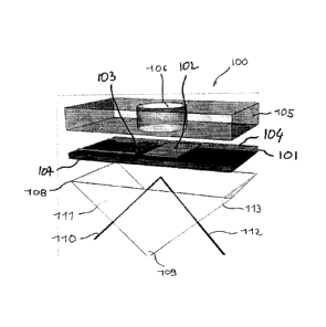
[0026] Referring to Figure 1, the SV-SAW/SPR sensing device 100
comprises a piezoelectric substrate 101. As illustrated in Figure 1, both the
SPR
sensing surface 102 and SV-SAW IDT electrodes 103 are integrated to the
common piezoelectric substrate 101. More specifically, both the SV-SAW IDT
electrodes 103 and SPR sensing surface 102 are thin metal films deposited on a
surface 104 of the common piezoelectric substrate 101. Several methods
including micro-fabrication methods can be used to produce the thin metal
films
PCT/CA2009/000550
CA 02721799 2010-10-18
WO 2009/129628 PCT/CA2009/000550
7
such as photolithography, lift-off, wet etching, etc. The thin metal films
forming the
SV-SAW IDT electrodes 103 and the SPR sensing surface 102 can be fabricated
simultaneously in a single step or separately in different steps.
[0027] An additional layer 105, for example made of polymer material,
is deposited on the surface 104 of the common piezoelectric substrate 101 over
the SV-SAW IDT electrodes 103 and the SPR sensing surface 102 to form a
fluidic well 106 to receive fluid containing the target element. As can be
seen in
Figure 1, the SPR sensing surface 102 is exposed at the bottom of the fluidic
well
106.
[0028] On a surface 107 of the common piezoelectric substrate 101
opposite to surface 104 is applied a surface 108 of a prism 109 generally
triangular or semi circular in cross section. SPR excitation light 110
propagates
along a SPR excitation light path through a surface 111 of the prism 109, the
prism 109 and the common piezoelectric substrate 101 to reach the thin metal
film
forming the SPR sensing surface 102. The reflected light 112 follows a light
path
from the thin metal film forming the SPR sensing surface 102 through the
common
piezoelectric substrate 101, the prism 109 and a surface 113 of the prism 109.
The prism is secured to the surface 107 of the substrate 101 with a substance
adapted to prevent light alteration between the prism 109 and the surface 107.
In
fact, the SPR excitation and reflected light paths are coupled to the thin
metal
layer forming the SPR sensing surface 102 through the prism 109 and the
common piezoelectric substrate 101. Those of ordinary skill in the art will
know
that a piezoelectric substrate 101 made for example of LiNb03will be
substantially
transparent to the SPR visible and near-infrared excitation and reflected
light.
[0029] For example, the attachment of a target element in the fluid
contained in the fluidic well 106 to ligands bound to the SPR sensing surface
102
can be monitored using SPR in the Kretschmann configuration. The principle of
operation of the Kretschmann SPR configuration is shown in Figure 2. More
specifically, Figure 2 is a schematic diagram of a Kretschmann SPR
configuration
PCT/CA2009/000550
CA 02721799 2010-10-18
WO 2009/129628
PCT/CA2009/000550
8
200.
[0030]
Referring to Figure 2, SPR excitation polarized light 110 is
produced by a light source 201 over a given spread of incidence angles a. To
produce the given spread of incidence angles a, the light source 201 may use,
for
example, mechanical scanning or dispersive optics (not shown).
[0031] The SPR
excitation polarized light 110 propagates along the
SPR excitation light path through the surface 111 of the prism 109, the prism
109
and the common piezoelectric substrate 101 to reach the thin metal film 202,
for
example a gold film, forming the SPR sensing surface 102. The reflected light
112
follows the light path from the thin metal film 202 through the common
piezoelectric substrate 101, the prism 109 and the surface 113 of the prism
109. In
fact, the SPR excitation and reflected light paths are coupled to the thin
metal
layer 202 forming the SPR sensing surface 102 through the prism 109 and the
common piezoelectric surface 101.
[0032] The
capture of a target element by a ligand on the sensing
surface 102 produces changes in the surface plasmon coupling conditions in the
thin metal film 202. At a specific critical angle, which is dependent upon the
index
of refraction in the dielectric medium in contact with the SPR sensing surface
102
of the thin metal film 202, the incident excitation polarized light 110 will
couple
strongly into the surface plasmons propagating on the metallic sensing surface
102 and a minimum amplitude will be observed in the reflected light 112
detected
through an optical detector 204. Capture of a target element such as 208 by a
ligands such as 209 can be tracked by detecting a shift 207 in the angular
position
of the minimum 206 of the reflectivity curve 205 (Intensity of reflected light
versus
angle of propagation of the reflected light). Minimum point I corresponds to
the
angular position of the minimum 206 of the reflectivity curve 205 without
binding of
the target element, and minimum point II corresponds to the angular position
of
the minimum 206 of the reflectivity curve 205 with binding of the target
element.
PCT/CA2009/000550
CA 02721799 2010-10-18
WO 2009/129628 PCT/CA2009/000550
9
[0033] The SPR configuration of Figure 2 is inverted (prism on top,
fluid on the bottom) relative to the configuration of Figure 1. The fluidic
subsystems are also different. In Figure 1, the fluidic subsystem is a fluidic
well
106 while in Figure 2 the fluidic subsystem is a flow-through channel 210.
Fluid
flow through the channel 210 wherein the target element such as 209 is bound
by
the ligand such as 208 on the sensing surface 102. Of course, the flow-through
channel 210 is designed to allow the fluid flowing therein to come into
contact with
the SPR sensing surface 102. However, the SPR working principle and
functionality in both cases are identical; this demonstrates that the SPR and
fluidics aspects can be implemented in the form of a plurality of different
embodiments.
[0034] SPR is believed to be otherwise well known to those of ordinary
skill in the art and, accordingly, will not be further described in the
present
specification.
[0035] As indicated in the foregoing description, shear-vertical surface
acoustic wave (SV-SAW) interdigited transducer (IDT) electrodes 103 of Figure
1
are mounted on the surface 104 of the common piezoelectric substrate 101 to
generate SV-SAW (also called Rayleigh waves). SV-SAW are mechanical
vibrations that propagate at the surface 104 of the piezoelectric substrate
101.
They are generated using thin-film metal IDT electrodes such as 103 deposited
on
the surface 104 of the piezoelectric substrate 101.
[0036] Referring to Figure 3A, an IDT 103 comprises a metallic comb-
like structure disposed on the surface 104 of the piezoelectric substrate made
for
example LiNb03. More specifically, the interdigited transducer (IDT) 103 of
Figure
3C comprises a first comb-like electrode 301 and a second comb-like electrode
302 (both shown in part only in Figure 3C). The comb-like electrodes 301 and
302
define respective fingers 303 and 304 alternating with each other and
intermeshed
with each other to form the IDT electrode structure of Figures 3C and 3D. The
width and spacing of the alternating, intermeshed fingers 303 and 304 are
PCT/CA2009/000550
CA 02721799 2010-10-18
WO 2009/129628
PCT/CA2009/000550
adjusted to obtain the desired wavelength for the SV-SAW waves. In the same
manner, the length of the alternating, intermeshed fingers 303 and 304 is
adjusted
to obtain the desired width of the train of the SV-SAW waves. An electrical
signal,
for example a pulsed electrical signal, is applied across the comb-like
electrodes
301 and 302 and therefore across the fingers 303 and 304. The electrical
signal
applied across the comb-like electrodes 301 and 302 is also applied at the
resonance frequency fo (see 500 in Figure 5) for a maximum SV-SAW amplitude
across sections of the piezoelectric material of the substrate 101 to deform
(contract and extend) these portions of the piezoelectric material and convert
the
electrical energy into mechanical energy, more specifically into SV-SAW waves
propagating at the surface 104 of the common piezoelectric substrate 101 in a
direction perpendicular to the fingers 303 and 304. The IDT electrodes 103
generate SV-SAW waves with equal amplitudes in both directions and hence are
bidirectional.
[0037] Figure
3A is a schematic diagram showing generation of the
SV-SAW waves by means of the SV-SAW IDT electrodes 103 and the
propagation of the SV-SAW waves 305 on the surface 104 of the common
piezoelectric substrate 101, for example a piezoelectric substrate made of
LiNb03,
and the SPR sensing surface 104. The zoomed view of Figure 3B illustrates the
transfer (arrows 306) of acoustic energy into the fluid 307 that conducts
desorption
and mixing because of a radiation pressure 306 created in the fluid.
[0038] Since
the SPR sensing surface 102 and the SV-SAW IDT
electrodes 103 are both integrated to the surface 104 of the common
piezoelectric
substrate 101, the SV-SAW waves 305 propagate on the surface 104 of the
common piezoelectric substrate 101 towards the fluidic well 106, as seen on
Figure 1, or flow-through channel 210, as seen on Figure 2. More specifically,
the
SV-SAW waves will induce mixing of the fluid in the fluidic well 106 or the
flow-
through channel 210 (acoustic streaming) and desorption of non-target
element(s), for example unwanted parasitic bio-molecules, from the SPR sensing
surface 102.
PCT/CA2009/000550
CA 02721799 2010-10-18
WO 2009/129628 PCT/CA2009/000550
11
[0039] As illustrated in Figure 4, SV-SAW or Rayleigh waves deform
the surface 104 of the piezoelectric substrate 101 in a direction normal to
the
surface 104, like rolling waves on an ocean and accordingly transfers energy
(see
arrows 306 of Figure 3B) from the SV-SAW waves into the fluid either in the
fluidic
well 106 or the flow-through channel 210, both for accelerated microfluidic
mixing
and desorption. This will accelerate microfluidic mixing and desorption to
improve
sensitivity and throughput of SPR sensing device and method.
[0040] Analysis of experimental results has confirmed accelerated
mixing and reaction times and removal (desorption) of non-specifically bound
elements such as parasitic bio-molecules. SPR has successfully been performed
on a piezoelectric substrate made for example of LiNb03. By conducting
desorption to remove non-target element(s), for example non-specifically bound
chemical species from the SPR sensing surface 102, SV-SAW increases the
signal-to-noise ratio of the SPR measurements.
[0041] Experiments have also confirmed that a SPR metal sensing
surface coated with a thin film of Si02 (10 nm thickness) appropriate for
aminosilane-based chemistry could be used to perform SPR on a LiNb03
substrate.
[0042] Figure 6 is a graph showing SPR reflectivity curves using a
LiNb03-based substrate for nine (9) fluids (liquids) with different optical
refractive
indices (n1=1.3300; n2=1.3325; q3=1.3350; n4=1.3375; n6=1.3400; n6=1.3425;
n7=1.3450; n8=1.3475 and n9=1.3500). More specifically, Figure 6 shows
shifting
of the SPR reflectivity curves to the right (larger angles of minimum
reflectivity)
with increasing refractive index, using a set of fluids with pre-calibrated
values of
refractive index.
[0043] The SPR performance of the LiNb03-based chip was also
experimented with a standard affinity assay: biotin-avidin in a phosphate
buffer
PCT/CA2009/000550
CA 02721799 2010-10-18
WO 2009/129628 PCT/CA2009/000550
12
(PBS), as shown in the graph of Figure 7A, where a biotinylated bovine serum
albumin (BSA) complex is adsorbed on the SPR sensing surface, followed by the
introduction of avidin which has a strong affinity for biotin. The increased
mixing
efficiency under the action of SV-SAW is shown in the graph of Figure 7B.
Under
identical experimental conditions over the same time interval, the graph of
Figure
7B clearly shows that more material (avidin) has bound to the BSA-biotin
complex
on the surface, as demonstrated by the greater shift of the right-most SPR
curve.
[0044] Figure 8 is a photograph of an example of SV-SAW/SPR
sensing device chip showing an embodiment of layout of the IDT and SPR metal
sensing surfaces on the common piezoelectric substrate.
[0045] Embodiment Variations:
[0046] 1. Though SV-SAW can be used for removing non-target
element(s) non-specifically bound to the SPR sensing surface (desorption)
after a
chemical reaction has completed, SV-SAW can also be used to impede non-
specific absorption during the chemical reaction, thus dynamically increasing
the
efficiency of attachment of the target element(s) by covalent bonding
(specific) to
the ligand(s) on the SPR sensing surface.
[0047] 2. The SV-SAW waves transmit mechanical energy into the
fluid, both by mechanical deformation of the surface of the piezoelectric
substrate
but also via the electrical field. This creates turbulent flow in the fluid
which
accelerates mixing and chemical reaction, compared to slow mixing and reaction
times due to diffusion alone.
[0048] 3. The SV-SAW/SPR device and method according to the
present invention can be controlled using electronics and software under
various
configurations.
PCT/CA2009/000550
CA 02721799 2010-10-18
WO 2009/129628 PCT/CA2009/000550
13
[0049] 4. The SPR sensing area may comprise a single sensing area
or multiple sensing areas, such as in an array configuration used in SPR-
imaging
(SPRi).
[0050] 5. The common substrate can be a piezoelectric substrate as
described hereinabove or a non-piezoelectric substrate coated with a
piezoelectric
film made for example of polycrystalline piezoelectric material (ZnO, BiTa03,
PZT,
PbZr03, AIN, etc.), single crystal materials (LiTa03), quartz, langasite
(La3Ga5S1014), or GaPO4 (example: Lee, et al. Integrated ZnO surface acoustic
wave microfluidic and biosensor system, in IEEE International Electron Devices
Meeting - IEDM '07, Washington, DC, USA, 2007).
[0051] 6. The SPR configuration is not limited to the Kretschmann
configuration: other SPR configurations such as that using waveguides (Krol et
al.,
Patent US 6,829,073 B1) and/or diffractive optical elements (Knoll et al.
Surface
plasmon-field-enhanced diffraction sensor. US Patent Application 2006/0194346
A1 and European Patent Application EP20050003435., and Thirstrup et. al.
Diffractive optical coupling element for surface plasmon resonance sensors.
Sensors and Actuators B (Chemical), 2004, 100(3): p298-308) could also be
used.
[0052] 7. The SPR configuration can use angle-scanning systems
(mechanically-scanned or parallel systems using a non-collimated beam), angle-
dispersive systems, wavelength-scanned systems (tunable wavelength source or
parallel chromatically dispersive system), hybrid systems (simultaneous angle
and
wavelength scanning systems), as well as near-resonance optical phase scanning
systems.
[0053] 8. The SV-SAW IDT electrodes and SPR sensing surfaces can
be fabricated from various metals, gold being the most common. Other examples
include silver, copper, aluminium, palladium, etc. A coating may be applied to
the
metal to protect its surface and/or to facilitate organic chemistry
functionalization.
PCT/CA2009/000550
CA 02721799 2010-10-18
WO 2009/129628 PCT/CA2009/000550
14
A typical approach for coating is to use a thin film of silicon dioxide,
although the
use of other coating materials can also be envisaged.
[0054] 9. The IDT electrodes are not limited to rectilinear electrodes
and can be fabricated in a wide variety of geometries depending on the kind of
SV-SAW propagation desired such as bulk, surface skimming bulk, etc. (for
example: Wu, et al. Actuating and detecting of microdroplet using slanted
finger
interdigital transducers. J. of Applied Physics, 2005, 98(2): p024903-7). The
frequency of the pulse excitation of the IDT electrodes can typically be of
the order
of between 10 to 1000 MHz, although such frequency can be adapted to the
particular microfluidic system.
[0055] 10. In terms of manufacturability, both the SPR sensing surface
and SV-SAW IDT electrodes involve metal deposition requiring resolutions that
are easily achievable with low-cost lithography commercial fabrication
methods.
[0056] 11. It is possible to use SV-SAW configurations comprising
either a single or multiple IDTs, depending on the requirements of the
particular
application. Also, the IDTs can be used for fluid droplet actuation and
pulse/echo
fluid droplet localization (Renaudin, et al. Surface acoustic wave two-
dimensional
transport and location of microdroplets using echo signal. Journal of Applied
Physics, 2006, 100(11): p116101-1).
[0057] 12. The fluidic subsystem may comprise a number of possible
embodiments: fluidic droplet, fluid in a well, fluid in a flow-through
microfluidic
channel, etc.
[0058] 13. The term fluid may encompass pure liquids, mixtures,
suspensions, colloids and dispersions as well as liquids in which solid
material, for
example, biological materials (such as cells, DNA, proteins, molecules, drugs,
chemical compounds, nucleic acids, peptides, etc.) or carbon nanotubes are
PCT/CA2009/000550
CA 02721799 2010-10-18
WO 2009/129628 PCT/CA2009/000550
contained.
[0059] 14. Although foregoing examples pertain to detection of
bioassays or biological material, the present invention applies equally well
to
detection of inorganic elements such as inorganic molecules or inorganic
substances.
[0060] 15. Many arrangements of SV-SAW IDT electrodes and SPR
sensing surface on the common substrate are possible of which Figure 8 is only
an example. Figure 8 is not to be understood as superceding the generality of
the
foregoing description.
[0061] 16. Although the integrated SV-SAW/SPR device and method
has been described herein above for detecting bio-molecules in a fluid, it
should
be understood that the integrated SV-SAW/SPR device and method can also be
used to perform a wide variety of studies, for example the study of cell
attachment,
cell migration, drug permeability and solubility, virus detection and protein
secretion, carbon nanotubes (CNTs) adsorption.
[0062] 17. Although the foregoing description only explicitly mentions
SPR combined with SV-SAW, it should be kept in mind that it is possible to use
any sensing technology other than SPR that uses thin metal films on the same
substrate as the SV-SAW IDT, such as resonant waveguide grating (RWG)
sensing (K. Tiefenthaler and W. Lukosz, "Sensitivity of grating couplers as
integrated-optical chemical sensors," Journal of the Optical Society of
America,
6(2), 1989, p.209-220) or microcalorimetry (A. Bourque-Viens, V. Aimez, A.
Taberner, P. Nielsen and P. G. Charette. Modelling and experimental
validation
of thin-film effects in thermopile-based microscale calorimeters," Sensors and
Actuators A: Physical, 150( 2), 2009, p.199-206).
[0063] 18. Although the foregoing specification describes SV-SAW, it
CA 02721799 2017-01-05
Patent Application No. 2,721,799
16
should be kept in mind that SV-SAW can be replaced by any other technology
capable of producing a mechanical wave propagating at the surface of a
substrate, the mechanical wave comprising shear-vertical components sufficient
to
adequately mix a fluid for the purposes of the application of concern.
[0064] 19. The
method for detecting a feature of a fluid or a target
element in the fluid can be used for the purpose of analyzing binding kinetics
(such as affinity constants, dissociation constant, equilibrium conditions,
time
constants, etc.) in assays involving analytes such as DNA, proteins,
antibody/antigens, pathogens, and other biomolecules.