Note: Descriptions are shown in the official language in which they were submitted.
CA 02722396 2010-10-22
WO 2009/131645 PCT/US2009/002421
TITLE
100011 Methods and Apparatus for Segregation of Particles
BACKGROUND OF THE DISCLOSURE
[0002] Among the basic operations necessary for studying or using
particles is the
ability to segregate different types of particles. For example, innumerable
applications in
the field of cell biology require the ability to segregate cells of one type
from cells of
another type. Applications in the field of industrial waste management require
the ability to
segregate solid particles from industrial waste water or waste gasses.
Applications in the
field of agriculture and food processing require the ability to separate
particulate
contaminants from particulate food products such as grains.
100031 For example, blood drawn from the umbilicus shortly after delivery
("cord
blood") is a rich source of stem cells, such as embryonic stem cells and
hematopoietic stem
cells. Hematopoietic stem cells are useful for treating blood disorders.
Methods of storing
cord blood samples are known. These methods have the drawback that a
relatively large
volume (e.g., 100 to 250 milliliters) of blood must be stored in order to
preserve a sufficient
number of stem cells for use in future medical procedures. The large volume of
cord blood
that is stored increases the cost and decreases the convenience of the
procedure. The stored
volume could be decreased significantly (e.g., to 0.1 to 1 milliliter) if stem
cells could be
readily separated from cord blood prior to storage. However, present methods
of separating
stem cells from cord blood are expensive, cumbersome, and sometimes
ineffective. There is
a need for an efficient and cost-effective method of segregating stem cells
from cord blood.
100041 Further by way of example, cells of apparently fetal origin (i.e.,
fetal-like cells)
can be found in the blood of pregnant women and in the blood of women who have
previously been pregnant. These cells can have male DNA when the mother has
given birth
to or is pregnant with a male child, and therefore the DNA appears to
originate from the
fetus. These cells are rare in the maternal bloodstream; there may be only 10
to 12 cells per
milliliter of maternal blood. Among fetal-like cells observed in maternal
blood, fetal
trophoblasts can degrade relatively quickly after the woman gives birth. Other
kinds of
fetal-like cells have been reported to endure in the blood of women for years
or decades
following pregnancy albeit in small numbers. The rarity and apparently short
duration of
some fetal-like cells can make them difficult to capture. Consequently, little
is known about
the cells. A need exists for a way to quickly, economically, and effectively
segregate fetal-
CA 02722396 2010-10-22
WO 2009/131645 PCT/US2009/002421
like cells from maternal blood. A need also exists for a way to segregate
fetal trophoblasts
from other fetal-like cells in maternal blood.
[0005] Mechanical devices intended for manipulation of biological cells
and other small
particles and having structural elements with dimensions ranging from tens of
micrometers
(the dimensions of biological cells) to nanometers (the dimensions of some
biological
macromolecules) have been described. For example, U.S. Patent number
5,928,880, U.S.
Patent number 5,866,345, U.S. Patent number 5,744,366, U.S. Patent number
5,486,335,
and U.S. Patent number 5,427,946 describe devices for handling cells and
biological
molecules. PCT Application Publication number WO 03/008931 describes a
microstructure
for particle and cell separation, identification, sorting, and manipulation.
[0006] Passage of blood through a space, defined in one dimension in
microns, presents
challenges. Tidal pressure forces which tend to disrupt cellular integrity and
potential
clogging of the passage space due to "packing" of cells must be taken into
account. This is
also complicated by the tendency of blood to clot (in a cascading manner) if
cellular
integrity is compromised. Furthermore, it is known that large particles
(cells, agglomerated
cells, extracellular materials, and poorly characterized "debris" in
biological samples can
clog the fluid passages of prior devices, inhibiting their efficiency and
operation.
[0007] The subject matter disclosed herein can be used to segregate and
manipulate
biological cells, organelles, and other particles from mixed populations of
particles or cells.
SUMMARY OF THE DISCLOSURE
[0008] The present disclosure relates to an apparatus for segregating
particles such as
cells. The apparatus includes a body, a cover, and a separation element. The
body and
cover define a void. The separation element is contained within the void. The
void has a
fluid inlet region and a fluid outlet region. The separation element has a
shape that defines a
stepped passageway that fluidly connects the inlet and outlet regions in the
void. The
separation element includes a first step and a second step, each of which
extends into the
stepped passageway. The passage bounded by the second step is narrower than
the passage
bounded by the first step. When a fluid including particles is present at the
inlet region,
fluid can flow from the inlet region, through the first passage, through the
second passage,
and into the outlet region. Particles suspended in the fluid can transit the
first and second
passages if the size of the particles does not exceed the narrow dimension of
each passage,
or if the particles are sufficiently deformable that, in a deformed shape,
they can squeeze
- 2 -
CA 02722396 2010-10-22
WO 2009/131645 PCT/US2009/002421
through each passage. Particles can be segregated by selecting a narrow
dimension for the
second passage that permits only some of the particles to pass therethrough.
The narrow
dimension of the first passage can be selected such that particles in the
fluid can pass
through the first passage individually, but two particles cannot pass through
the first passage
simultaneously if they are stacked across the narrow dimension of the first
passage.
[0009] The apparatus can include a fluid inlet port for facilitating
fluid flow from
outside the apparatus into the inlet region, a fluid outlet port for
facilitating fluid from the
outlet region to the outside of the apparatus, or both. A fluid displacement
device (e.g., a
pump or a gravity-fed fluid reservoir can be fluidly connected with one or
both of the inlet
and outlet ports to facilitate fluid flow through the stepped passageway. Such
flow can be in
the direction from the inlet region toward the outlet region, for the purpose
of segregating
particles. Fluid flow can be in the direction from the outlet region toward
the inlet region,
for example to flush out particles that were unable to traverse the second
passage during
inlet region-to-outlet region fluid flow.
[0010] The steps of the separation element define passages within the
stepped
passageway, and there can be two or more such steps. The steps can be formed
from planar
regions that meet at a right angle (forming classical right-angled steps), or
the riser portion
(i.e. the transitional face) of the step can be inclined, such that a first
planar step region can
be connected to a second planar step region by a sloped flat surface or by a
curved surface.
The planar step regions can be substantially parallel to a portion of the
cover, a portion of
the body, or both, and should have a length (in the direction of bulk fluid
flow) equal to a
multiple (e.g., 2, 4, 10, or 1000) of the narrow dimension of the passage it
bounds. The
width of the planar region (in the direction perpendicular to bulk fluid flow)
should be equal
to a multiple (e.g., 10, 1000, of 10000) of the narrow dimension of the
passage it bounds.
100111 The apparatus can have one or more supports within the void for
maintaining the
dimensions of the stepped passageway during assembly and operation of the
device. The
support can completely span the distance between the separation element the
body or the
cover or it can span only a portion of that distance, to provide room for
deformation of an
element (e.g., upon assembly and clamping of the apparatus).
100121 The present disclosure includes a method of segregating particles.
The method
includes introducing particles at the inlet region of the apparatus,
permitting them to move
(i.e., by endogenous cell motility or under the influence of induced fluid
flow) through a
-3-
CA 02722396 2010-10-22
WO 2009/131645 PCT/US2009/002421
stepped passageway to an outlet region. At least some of the particles are
prevented from
entering the outlet region by a step in the passageway, resulting in
segregation of the
particles. Particles able to traverse all steps in the stepped passageway can
be collected
from the outlet region. Particles unable to traverse at least one step in the
stepped
passageway can be collected from a portion of the passageway upstream from the
step that
inhibits their movement through the passageway. For example, trapped particles
can be
recovered by inserting a device (e.g., a catheter) into the stepped
passageway, by reversing
fluid flow and flushing the trapped cells out of the passageway by way of the
inlet region, or
by disassembling the device and recovering the trapped particles directly. If
the trapped
particles are cells, they can be lysed within the stepped passageway and the
lysis products
collected by flow in either direction.
BRIEF DESCRIPTION OF THE SEVERAL VIEWS OF THE DRAWINGS
[0013] The foregoing summary, as well as the following detailed
description of the
invention, will be better understood when read in conjunction with the
appended drawings.
These drawings are included for the purpose of illustrating the disclosure.
The disclosure is
not limited to the precise arrangements and instrumentalities shown.
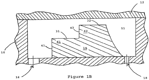
[0014] Figure 1 consists of Figures lA and 1B. Figure IA is an elevated
view of a
portion of the apparatus in one embodiment. Figure 1B is a vertical section of
the portion of
the apparatus shown in Figure 1A, taken along plane 1B, showing a body 10
which defines
a void 11. A cover 12 is disposed across the void 11 forming a fluid-tight
seal with the
body 10. A separation element 14 having a first step 61 and a second step 62
is disposed
within the void 11 between an inlet port 16 and an outlet port 18. The first
step 61 has a
broad surface 31 and a transitional face 41. The second step 62 has a broad
surface 32 and a
transitional face 42.
[0015] Figure 2 consists of Figures 2A, 2B, and 2C. Figure 2A is an
elevated view of a
portion of the apparatus in an embodiment having inner support structures 20.
Figure 2B is
a vertical section of the portion of the apparatus shown in the Figure 2A,
taken along plane
2B. Figure 2C is a vertical section of a portion of the apparatus shown in
Figure 2A, taken
along plane 2C.
[0016] Figure 3 consists of Figures 3A and 3B and illustrates a
configuration of the
apparatus described herein wherein the geometry of the first and second
passages can be
selected to achieve substantially constant linear flow velocity throughout the
first and
-4 -
CA 02722396 2010-10-22
WO 2009/131645 PCT/US2009/002421
second passages. Figure 3A is an elevated view of a series of passages wherein
the width of
each passage increases in the direction from the inlet region to the outlet
region. Figure 3B
is a vertical section of the series of passages shown in Figure 3A taken along
plane 3B,
wherein the height of each passage decreases in the direction from the inlet
region to the
outlet region.
[0017] Figure 4 is a perspective view of a portion of a separation
element showing the
length "t", height "fi", and width "at" of a step, and indicating the
direction of bulk fluid
flow "BFF" past the step.
[0018] Figure 5 is a color image showing an elevated view of the cover 12
of an
assembled apparatus, showing the light pattern in an appropriately assembled
apparatus, as
described herein in Example 2.
[0019] Figure 6 is a diagram that illustrates the relative arrangements
of the cover 12,
base 10, and first, second, third, fourth, fifth, sixth, seventh and eighth
steps (61-68) of the
separation element 14 of an apparatus used in experiments described herein in
Examples 3
and 4. The direction of fluid flow is shown as 'D.'
[0020] Figure 7 is a map showing the approximate locations within the
separation
region of the experiments described herein in Example 4 at which fetal-like
cells were
found. The portion of the Relative Vertical Position designated "Outlet Area"
corresponds
approximately to the portion of the cassette at which steps having cover-to-
step distances of
4.2 and 4.4 micrometers were located, and the portion of the Relative Vertical
Position
designated "Inlet Area" corresponds approximately to the portion of the
cassette at which
steps having cover-to-step distances of 5.2 and 5.4 micrometers were located.
DETAILED DESCRIPTION
[0021] The disclosure relates to an apparatus for segregating particles
on the basis of
their ability to traverse a passage. Particles (e.g., particles suspended in a
liquid or gaseous
fluid or particles in a vacuum) are moved through a stepped passageway defined
by a
separation element in the apparatus. The stepped passageway contains at least
two passages
that are fluidly connected in series, each passage having a narrow dimension.
Most or all
particles in the fluid are able to move into the first passage, but only some
of the particles
are able to move through the second passage. The net result is that some
particles can move
through the entire stepped passageway, while other particles are retained
within the
apparatus, such as within the first passage. Segregation of particles is thus
achieved.
- 5 -
CA 02722396 2016-11-03
Movement of particles can be motivated by fluid flow, gravity, vibration, or
any
combination of these, for example.
[0022] Definitions
[0023] As used herein, each of the following terms has the meaning
associated with it in
this section.
[0024] As illustrated for rectangular steps in Figure 4, the "length" of
a step (or of the
passage bounded by the step; "e" in Figure 4) refers to the distance that the
step extends in
the direction of bulk fluid flow through the passage corresponding to the
step.
[0025] As illustrated for rectangular steps in Figure 4, the "height" of
a step ("V in
Figure 4) refers to the distance that the step extends in the direction away
from the
separation element beyond the preceding (i.e., upstream) step surface.
[0026] As illustrated for rectangular steps in Figure 4, the "width" of a
step (or of the
passage bounded by the step; "w" in Figure 4) refers to the distance that the
step extends in
the direction that is perpendicular to bulk fluid flow over the step.
[0027] The "narrow dimension" of a passage refers to the distance between
the broad
portion of a step of the separation element and the opposed, generally
parallel, face of the
apparatus (e.g., the face of the cover or body that faces the void). For
example, for a
passage having a rectangular cross-section in a plane taken perpendicular to
the direction of
bulk fluid flow through the passage, the narrow dimension of the passage is
the length of a
line in that plane extending between and at right angles to each of the flat
surface of the step
and the flat surface of the opposed face of the apparatus. Further by way of
example, the
"narrow dimension" of each of passages 51 and 52 in Fig. 2B is the minimum
distance
between each of the step surfaces 31 and 32 and the nearest surface of cover
12.
[0028] The "flow area" of a passage is a cross-section of the passage
taken in a plane
perpendicular to the direction of fluid flow in the passage.
[0029] Detailed Description
[0030] The disclosure relates to an apparatus for segregating particles
on the basis of
their ability to flow through at least two passages, the second (downstream)
passage 52
being narrower than the first (upstream) passage 51. The apparatus includes a
separation
element 14 disposed in avoid 11 formed by a body 10 and cover 12. Within the
void II,
the separation element 14 separates an inlet region 15 of the void from an
outlet region 17 of
the void. The inlet and outlet regions are in fluid communication by way of a
stepped
- 6 -
CA 02722396 2010-10-22
WO 2009/131645 PCT/US2009/002421
passageway defined by the separation element 14 and one or both of the body 10
and cover
12. Steps formed in the separation element define the first and second
passages. The
apparatus optionally has an inlet port 16 that fluidly communicates with the
inlet region 15
of the void 11 and an outlet port 18 that fluidly communicates with the outlet
region 17 of
the void 11, to facilitate provision and withdrawal of fluid to the inlet and
outlet regions.
[0031] In operation, particles in the inlet region 15 pass into the first
passage 51 and, if
they are able, into the second passage 52. Particles in the second passage 52
pass to the
outlet region 17. Cells that are not able to pass into or along the second
passage 52 do not
reach the outlet region 17. In this way, particles able to reach the outlet
region 17 are
segregated from particles that are not able to reach the outlet region 17. The
two
populations of particles can be separately recovered from the apparatus. For
example,
particles at the outlet region 17 can be recovered in a stream of liquid
withdrawn from the
outlet region 17 (e.g., by way of an outlet port or by way of a catheter
inserted into the
outlet region 17. Particles unable to pass through the second passage 52 to
the outlet region
17 can be recovered by flushing them, in the reverse direction, through the
first passage 51
and into the inlet region 15. Such particles can be withdrawn from the inlet
region 15.
Alternatively, particles unable to pass through the second passage 52 to the
outlet region 17
can be left in the apparatus or recovered by disassembling the apparatus.
Particles unable to
enter either the first passage 51 or the second passage 52 can be recovered
from the inlet
region 15.
[0032] The apparatus described herein can be used in a wide variety of
applications. In
addition to segregating particles from a mixed population of particles, the
device can be
used in applications in which one or more of the segregated particle
populations are
identified or further manipulated, for example. The construction and operation
of the
apparatus resist clogging by the particles being segregated, relative to
devices previously
used for particle separation. Advantageously, the particles segregated using
the apparatus
described herein can be suspended in a liquid or gaseous fluid, or in no fluid
at all (e.g., in a
vacuum). Furthermore, any fluid in which particles are suspended can either be
flowed
through the apparatus or remain static. That is, particles can be segregated
regardless of
whether any fluid in which they are suspended is caused to move through the
spaces of the
apparatus. Thus, for example, particles in a mixture of dry particles can be
segregated by
providing the mixture to the inlet region and vibrating or shaking the device
(oriented such
- 7 -
CA 02722396 2010-10-22
WO 2009/131645 PCT/US2009/002421
that gravity will tend to draw the particles through the separation region).
Such use can be
beneficial in situations in which suspension of particles in a fluid is
considered undesirable
or unnecessary (e.g., when separating plant seeds from other particulate
matter such as seeds
of other plants).
[0033] Parts and portions of the apparatus are now discussed separately in
greater detail.
[0034] The Body and Cover
[0035] The apparatus has a body 10 and a cover 12 defining a void 11
therebetween. A
portion of the void 11, defined in part by the separation element 14, is a
stepped
passageway. The stepped passageway is also defined by a surface of the body
10, a surface
of the cover 12, or by a combination of these, that is opposed to the stepped
surface(s) 31
and 32 of the separation element 14. (i.e., in an orientation such that the
stepped
passageway-defining surface(s) of the body 10 and/or cover 12 contact the
stepped
passageway-defining surface(s) of the separation element 14 in such a way that
the surfaces
form an extended lumen (i.e., the stepped passageway) between the surfaces. In
order to
simplify construction of the apparatus, most or all of the stepped passageway-
defining
surfaces can be formed or machined into a separation element 14 that is an
integral part
formed in a recess of the cover 12 or the body 10, the recessed portion being
surrounded by
a flat surface, so that the opposed surface of the body 10 or the cover 12
need only be
another flat surface in order to form the stepped passageway upon contact
between the flat
surfaces of the body 10 and cover 12.
[0036] The separation element 14 is preferably integral with (formed or
machined as a
part of) one of the body 10 and the cover 12. In this embodiment, the
operative portion of
the apparatus consists of essentially two pieces -- either a cover 12 and a
body 10 having a
separation element 14 as a part thereof, or a body 10 and a cover 12 having a
separation
element 14 as a part thereof. It is not important which of the body 10 and
cover 12 bears the
separation element 14, because the body 10 and cover 12 form the walls of and
define the
void 11 in which the separation element 14 is disposed. Preferably, a portion
of the part not
bearing the separation element 14 is simply a flat surface that mates with
flat edges of the
part bearing the separation element 14 and having the void 11 therein, so that
upon
assembly of the two parts, the void 11 is sealed by mating of the flat
surfaces and the
separation element 14 is disposed within the thus-sealed void 11. In this
embodiment, one
of the parts has both the void 11 and the separation element 14 formed or
machined therein
- 8 -
CA 02722396 2010-10-22
WO 2009/131645 PCT/US2009/002421
or, alternatively, has the void 11 formed or machined therein and has the
separation element
14 placed, assembled, formed, or adhered within the void 11.
[0037] The shapes of the body 10 and cover 12 are not critical, except
for the portion(s)
of the body 10 and/or cover 12 that define the stepped passageway in the void
11 and the
portion(s) of the body 10 and cover 12 that mate to seal the void 11. The
requirements of
the portion(s) of the body 10 and/or cover 12 that define the stepped
passageway are
discussed in the section of this disclosure pertaining to the stepped
passageway. The
portion(s) of the body 10 and cover 12 that mate to seal the void 11 do not
have any
particular shape or location requirements, other than that they should seal
the void 11 when
the apparatus is assembled, with allowances for any orifices (e.g., inlet or
outlet ports) that
are bounded by both the body 10 and the cover 12. Sealing can be achieved by
direct
contact between the relevant portions of the body 10 and cover 12.
Alternatively or in
addition, sealants such as adhesives, greases, gaskets, waxes, and the like
can be applied on
the sealing surfaces of the body 10 and cover 12. The seal should be able to
withstand the
anticipated internal pressure generated within the apparatus during its
operation. For
example, in many embodiments, an internal fluid pressure greater than 25
pounds per square
inch of gauge pressure (psig) would be unusual, and a seal capable of
preventing fluid leaks
at this pressure should suffice for such embodiments. More typical operation
pressures in
embodiments in which biological cells are separated using the apparatus are
anticipated to
be within the range >0-15 psig. In some embodiments, the apparatus can be
operated by
application of negative (i.e., vacuum) pressure to the outlet region, in which
embodiments
the seal should prevent the passage of air or liquid from outside the device
into the void
(other than, of course, by way of the inlet region).
[0038] The size and shape of the remaining portions of the body 10 and
cover 12 are not
critical and can be selected to facilitate, for example, manufacturing,
handling, or operation
of the apparatus. By way of example, for an apparatus having a substantially
flat cover 12
(e.g., like a cover slip for a microscope slide), the body 10 can have the
void 11 and
separation element 14 formed or machined therein, and portions of the body 10
outside the
void 11 can be formed or machined to adapt the body 10 for securing it in a
frame or holder
of fixed geometry. Thus, for example, the body 10 can have flanges, handles,
threaded
holes, smooth bores, impressions or indentations for holding a clamp, or other
features
formed, applied, or machined therein or thereon, and such features can
facilitate
- 9 -
CA 02722396 2010-10-22
WO 2009/131645 PCT/US2009/002421
reproducible orientation of the body 10 in a device for operating the
apparatus or
reproducible orientation of the body 10 in a device for machining one or both
of the void 11
and the separation element 14 in the body 10.
[0039) The body 10, the cover 12, or both can define a port through which
fluid can be
introduced into or withdrawn from the void 11. For example, the body 10 can
define an
inlet port 16 that fluidly communicates with the inlet region 15. Fluid
introduced into the
inlet port 16 can flow into the inlet region 15, displacing fluid already
there (because the
void is sealed) into the stepped passageway, and thence into the first passage
51 and the
second passage 52 and into the outlet region 17. Particles suspended in fluid
in one of these
regions and passages can be carried into a downstream region or passage,
provided the
particle can flow through the present and intervening passages and regions.
Similarly,
withdrawal of fluid from the outlet region 17 by way of an outlet port 18
formed in the body
10 can induce fluid flow from passages in fluid communication with the outlet
region 17
and from passages and regions in fluid communication therewith.
[0040] Ports can be simple holes which extend through the cover or body, or
they can
have fixtures (burrs, rings, hubs, or other fittings) associated with them for
facilitating
connection of a fluid flow device to the port. The body 10, cover 12, or both
can define an
inlet port 16 in the inlet region 15 of the void 11, an outlet port 18 in the
outlet region 17 of
the void 11, or both an inlet port 16 and an outlet port 18. Fluid can be
introduced into the
inlet region 15 through the inlet port 16. Fluid can be withdrawn from the
outlet region 17
through the outlet port 18. Continuous introduction of fluid into the inlet
region 15 and
simultaneous withdrawal or emission of fluid from the outlet region 17 can
create a
continuous flow of fluid through the apparatus. Similarly, continuous
withdrawal of fluid
from the outlet region 17 and simultaneous influx or introduction of fluid
into the inlet
region 15 can create continuous flow.
[0041] The Void
[0042] The body 10 and the cover 12 form a void 11 when they are
assembled. The
void 11 has an inlet region 15, an outlet region 17, and a separation region
interposed
between the inlet region 15 and the outlet region 17. A separation element 14
is disposed
within the separation region and, together with the body 10, the cover 12, or
both, defines a
stepped passageway. The stepped passageway includes at least a first passage
51 and a
second passage 52, that are fluidly connected in series and that are defined
by steps in the
-10-
CA 02722396 2010-10-22
WO 2009/131645 PCT/US2009/002421
separation element 14. The stepped passageway can include any number of
additional steps,
each of which can define an additional passage in the void.
[0043] During operation of the device, at least the inlet region 15, the
outlet region 17,
and the stepped passageway of the void 11 are filled with a fluid. Preferably,
the entire void
11 is filled with fluid during operation. In one embodiment, the only fluid
path that
connects the inlet region 15 and the outlet region 17 is the stepped
passageway. Particles
present in the inlet region 15 can enter and pass through the first passage 51
of the stepped
passageway unless they are excluded by the size (i.e., the narrow dimension)
or shape of the
first passage 51. Particles present in the first passage 51 can enter the
second passage 52
unless they are excluded by the size (i.e., the narrow dimension) or shape of
the second
passage 52, or unless their movement through the first passage 51 is inhibited
by the size
(i.e., the narrow dimension) or shape of the first passage 51. Particles
present in the second
passage 52 can enter the outlet region 17 unless their movement through the
second passage
52 is inhibited by the size (i.e., the narrow dimension) or shape of the
second passage 52.
Movement of particles within the apparatus can be induced by fluid flow
through the
apparatus, by intrinsic motility of the cells, or a combination of the two.
Over time,
particles unable to enter the first passage 51 will be segregated in the inlet
region 15;
particles able to enter the first passage 51 but unable to enter the second
passage 52 (or to
freely move though the first passage 51) will be segregated in the first
passage 51; particles
able to enter the second passage 52 but unable to freely move therethrough
will be
segregated in the second passage 52; and particles able to move through both
the first
passage 51 and the second passage 52 will be segregated in the outlet region
17 (or in fluid
withdrawn or emitted from the outlet region 17).
[0044] Particles segregated in this manner can be recovered (using any of
a variety of
known methods, including some described herein) from their respective
locations. By way
of example, a catheter can be inserted into a region or passageway (e.g., the
inlet region 15
or the first passage 51) of the apparatus, and particles present therein can
be withdrawn by
inducing suction in lumen of the catheter. Further by way of example,
backflushing (i.e.,
fluid flow from the outlet region 17 in the direction of the inlet region 15)
can be used to
collect particles present in one or more of the inlet region 15, the first
passage 51, and the
second passage 52 in fluid collected, withdrawn, or emitted at the inlet
region 15. Still
further by way of example, particles present at the inlet region 15 can be
collected by a
-11-
CA 02722396 2010-10-22
WO 2009/131645 PCT/US2009/002421
transverse (relative to bulk fluid flow from the inlet region 15 to the outlet
region 17 by way
of the stepped passageway) fluid flow across the inlet region 15, using ports
provided for
this purpose in fluid communication with the inlet region 15.
[0045] The Separation Element
[0046] Situated in the void 11 defined by the body 10 and the cover 12 and
between the
inlet region 15 and the outlet region 17 of the void 11, the separation
element 14 is a part of
the apparatus that has a surface that defines part of the stepped passageway.
One or both of
the body 10 and the cover 12 define the remaining boundaries of the stepped
passageway,
which fluidly connects the inlet region 15 and the outlet region 17. The
separation element
14 has a shape that includes at least two steps, the steps forming at least
one of the
boundaries of each of the first passage 51 and the second passage 52. One or
both of the
body 10 and the cover 12 define the remaining boundaries of the first passage
51 and the
second passage 52.
[0047] The stepped passageway is the orifice through which particles
move, fluid flows,
or both, during operation of the apparatus. The separation element 14 has a
stepped
structure, which defines the stepped shape of at least one side of the stepped
passageway.
The separation element 14 has at least two steps, the first step 61 and the
second step 62.
The first step 61 defines a boundary of the first passage 51 in the stepped
passageway. The
second step 62 defines a boundary of the second passage 52, the second passage
52 having a
smaller narrow dimension (see, e.g., Figure 2B) than the first passage 51. The
first and
second passages are fluidly connected in series, the second passage 52 being
downstream
from the first passage 51 during normal operation of the apparatus. Fluid must
flow through
each of the first and second passages in the stepped passageway in order to
travel from the
inlet region 15 to the outlet region 17 when the apparatus is assembled.
[0048] The separation element 14 is associated with at least one of the
body 10 and the
cover 12. The separation element 14 can be attached to the surface of the body
10 or the
cover 12. The separation element 14 can instead be integral with one of the
body 10 or the
cover 12, such that when the body 10 and the cover 12 are assembled, the
stepped surface(s)
of the separation element 14 are brought into opposition with the surface(s)
of the body 10
or the cover (12) that form the boundaries of the stepped passageway.
Alternatively, the
separation element 14 can be a part separate from the cover 12 or the body 10.
If the body
10, the cover 12, and the separation element 14 are separate parts, then the
parts are
-12-
CA 02722396 2010-10-22
WO 2009/131645 PCT/US2009/002421
preferably dimensioned and shaped such that the separation element 14 is held
in place by
compression between the cover 12 and the body 10 when the apparatus is
assembled.
100491 Fluid pressures within the apparatus (e.g., within the second
passage 52) are
exerted on all surfaces contacted by the fluid, and such fluid pressures can
induce bending
or bulging in deformable materials. Furthermore, external pressure applied to
parts of the
apparatus in order to secure it in its assembled state (e.g., one or more
clamps which urge
the cover 12 against portions of the body 10) can also induce flexation or
bulging in flexible
materials that form one or more parts of the apparatus. Because the second
passage 52
defined by the separation element 14 and at least one of the body 10 and the
cover 12 is the
primary mechanism by which particles are segregated by the apparatus in
operation, it is
preferable that the narrow dimension of the second passage 52 be carefully
maintained
relatively constant across the width of the second step 62.
100501 By way of example, the second passage 52 has boundaries defined by
the second
step 62 of the separation element 14 and by one or both of the body 10 and the
cover 12.
Clamping the body 10 and the cover 12 together can exert external force on a
part which
forms a boundary of the second passage 52, thereby tending to induce flexation
of the part
and narrowing of the narrow dimension of the second passage 52. Such flexation
and
narrowing can be reduced or eliminated by including one or more supports 20
within the
lumen of the second passage 52. A support 20 can be, for example, a rod-shaped
extension
extending from the surface of the separation element 14 that defines the
boundary of the
second passage 52 in the direction of the opposed surface of the body 10 or
the cover 12.
Alternatively, an extension having a rectangular cross-section can extend away
from the
surface of the body 10 or the cover 12 that defines a boundary of the second
passage 52 in
the direction of the opposed surface of the separation element 14 can form a
support 20.
More than one support 20 can be arranged in parallel or in series to form one
or more solid
or segmented walls, and such supports can define multiple flow paths within
the void, the
multiple flow paths merging at one or both of their ends. As a third
alternative, a support 20
can be a discrete part disposed in the lumen of the second passage 52 and
substantially or
fully spanning the narrow dimension between the opposed surfaces of the
separation
element 14 and the body 10 or cover 12. Impingement of the support 20 upon the
surface of
the separation element 14 that defines the second passage 52, upon die surface
of the body
10 or cover 12 that defines the second passage 52, or upon both surfaces,
limits or halts
-13-
CA 02722396 2010-10-22
WO 2009/131645 PCT/US2009/002421
flexation of the surfaces, maintaining the narrow dimension to a value
substantially equal to
or greater than the thickness of the support 20 (e.g., to prevent the cover 12
from depressing
completely against the broad surface 32 of the second step 62 and reducing the
narrow
dimension of the second passage 52 below the desired value).
100511 The supports 20 brace the parts of the apparatus in their
appropriate
conformation, increasing the dimensional stability of the apparatus. By
increasing
dimensional stability, the supports 20 can enhance the operability of the
apparatus under
various operating conditions (e.g., with varying clamping pressures or with
varying fluid
pressures) and extend the life of the apparatus. Supports 20 can also enhance
the particle
segregating accuracy of the apparatus by preventing the body 10 or cover 12
from
deforming and altering the narrow dimensions of one or more of the first and
second
passages of the stepped passageway. Supports 20 can also be disposed in the
void 11
outside of the first and second passages, and span the height of the void.
Such supports 20
can maintain the patency of the void 11 outside the first and second passages.
Where a
support 20 is not integral with a surface impinged by the support 20, the
support 20 can be
not attached to the surface, adhered to the surface (e.g., using an adhesive
interposed
between and binding both the surface and a portion of the support), or fused
with the
surface.
100521 Supports 20 can separate an otherwise unitary fluid flow path into
two or more
.. fluid flow paths within the void 11 (see, e.g., supports 20 in Figure 2A).
In an embodiment
depicted in Figure 2, the apparatus consists of a flat cover 12, a body 10
having a flat
surface that mates with the cover 12 and defining a void 11 having an inlet
region 15 and an
outlet region 17, and a separation element 14 that includes a first step 61
and a second step
62 and is integral with four supports 20. When the separation element 14 is
disposed in the
void 11 between the inlet region 15 and the outlet region 17, the height of
the supports 20 is
equal to the depth of the void 11, such that the upper surfaces of the
supports 20 are
substantially co-planar with the flat surface of the body 10 (as depicted in
Figures 2B and
2C). When the cover 12 is assembled against the flat surface of the body 10,
the top
surfaces of the supports 20 contact the surface of the cover 12 that defines
the void 11,
thereby preventing clamping pressure (applied to the cover 12 to hold it flush
against the flat
surface of the body 10) from deforming the cover 12. The bracing provided to
the cover 12
by the supports 20 serves to maintain the narrow dimension of the second
passage 52 and
-14-
CA 02722396 2010-10-22
WO 2009/131645 PCT/US2009/002421
the narrow dimension of the first passage 51, even when clamping pressure that
would
otherwise deflect the cover 12 inwardly toward the void is applied to the
cover 12. If the
cover 12 is fused with or adhered to one or more of supports 20, then the
apparatus depicted
in Figure 2 can also resist expansion of the narrow dimension of the first
passage 51 and the
second passage 52 that might otherwise result from outward (i.e., away from
the void 11)
flexation of the cover 12 induced by fluid pressure within the apparatus.
100531 The shape, contour, size, and orientation of the supports 20 are
not critical.
Supports 20 can have rectangular, rhomboid, circular, elliptical, or wing-
shaped cross-
sections, for example. In addition to forming walls that direct fluid flow (as
do the supports
20 depicted in Figure 2), supports 20 can induce turbulence in fluid flow
paths and induce
mixing and or displacement of particles immediately downstream from such
supports. By
way of example, supports having rounded cross-sections and placed near the
leading (i.e.,
upstream-most) edge of the second passage 52 can induce turbulent flow at the
leading edge
of the second passage 52, jostling particles that might otherwise occlude the
second passage
52 and thereby enhancing fluid flow through the second passage 52.
100541 The separation element 14 can define fluid flow paths other than
the stepped
passageway discussed herein. Such fluid flow paths can, for example, extend
between the
inlet region 15 and the stepped passageway or between the stepped passageway
and the
outlet region 17. Further by way of example, the first passage 51 defined by
the first step 61
of the separation element 14 can be connected with the second passage 52
defined by the
second step 62 of the separation element 14 by way of a fluid flow path
defined by the
separation element (i.e., rather than the first passage 51 communicating
directly with the
second passage 52).
100551 In some applications, it is important that a sample of particles
present at the inlet
region 15 enter each of multiple stepped passageways at substantially the same
time. If a
device such as that depicted in Figure 2 is used, it is apparent that
particles provided to the
inlet region 15 by way of the inlet port 16 will arrive at the outermost
stepped passageways
(left-most and right-most passages in Figure 2A) later than they will arrive
at the stepped
passageway nearest the inlet port 16 (center passage in Figure 2A). With
reference to the
device depicted in Figure 2, the separation element 14 can define walls or
channels that
originate at the inlet port 16 and extend by various paths to each of the
individual stepped
passageways, such that the linear flow distance along each flow path is equal.
Thus, the
-15 -
CA 02722396 2010-10-22
WO 2009/131645 PCT/US2009/002421
flow path extending between the inlet port 16 and the central flow path will
be curved,
angled, or serpentine relative to the flow paths extending between the inlet
port 16 and the
outermost flow paths. The end result is that, because the linear flow paths
are of equal
lengths, particles provided to the inlet port end of each of the flow paths
will arrive at the
stepped passageway end of the flow paths at substantially the same time.
[0056] The separation element 14 includes at least two steps, including a
first step 61
nearer (along the stepped passageway) the inlet region 15 than a second step
62. Particles
suspended in a fluid flow through the stepped passageway that includes a first
passage 51
and a second passage 52 that has a smaller narrow dimension than the first
passage 51.
Most or all particles in the fluid are able to flow into the first passage 51,
but only some of
the particles are able to flow through the second passage 52. The net result
is that some
particles in the fluid can flow through the entire stepped passageway, while
other particles
are retained within the apparatus, such as within the first passage 51.
Segregation of
particles is thus achieved.
[0057] The steps of the separation element 14 can have any of a variety of
shapes. In
one embodiment (e.g., in the apparatus depicted in Figure 1), the first step
61 and the second
step 62 have a traditional 'staircase' step structure, i.e., two planar
surfaces that intersect at a
right angle. That is, the transitional face 41 of the first step 61 and the
broad face 31 of the
first step 61 meet at a right angle, as do the transitional face 42 of the
second step 62 and the
broad face 32 of the second step 62. Alternatively, the transitional and broad
faces of the
steps can meet at an angle between 90 and 180 degrees, as depicted in Figure
3, for
example. The transitional and broad faces of the steps can also meet at an
angle between 0
and 90 degrees, forming an overhang.
[0058] Steps that form an overhang and steps that have faces that meet at
angles near 90
degrees can induce turbulent flow near the edge at which the faces of the step
meet. Such
turbulence can dislodge particles that might otherwise occlude the passage
between the
broad face of the step and the opposed face of the body 10 or cover 12, and
this turbulence
can thereby inhibit clogging of the passage and enhance fluid flow (and reduce
fluid
pressure drop) through the device, which are beneficial effects. Furthermore,
when the step
forms an overhang and the height of the step is sufficiently large that
particles that might
otherwise clog the passage can reside in the recess formed by the overhang,
such steps can
also reduce clogging of the passage and improve performance of the apparatus.
To the
-16-
CA 02722396 2010-10-22
WO 2009/131645 PCT/US2009/002421
extent that the approximate size of relatively large, undesired particles in a
sample can be
predicted, one or more steps designed to capture or exclude such particles can
be
incorporated into the device in order to capture the undesired particles in a
place and
quantity that does not significantly inhibit fluid flow through the stepped
passageway.
[0059] Steps having transitional and broad faces that meet at an angle
between 90 and
180 degrees can occlude passage of particles having a variety of sizes (i.e.,
those having
sizes intermediate between the narrow dimension of the passage defined by the
broad face
of the step and the narrow dimension of the space upstream from the step. By
halting
passage of particles having slightly different sizes at different positions on
the transitional
face of the step, a step having transitional and broad faces that meet at an
angle between 90
and 180 degrees can prevent clogging of the passage defined by the broad face
of the step to
a greater degree than a step having transitional and broad faces that meet at
an angle of 90
degrees or less.
[0060] Clogging of fluid flow past a step by particles that occlude the
passage defined
by the broad face of the step can also be reduced or avoided by increasing the
width of the
step. Because each particle occludes fluid flow only for the flow area
obscured by the
particle, a wider step will necessarily be clogged by a greater number of
occluding particles.
The width of a step can be increased in either or both of two ways. First, the
width of the
step can be increased by simply increasing the linear width (as depicted in
Figure 4) of the
step. Second, the width of the step can be increased by increasing the length
of the edge at
which the broad and transitional faces of the step meet by decreasing the
linearity (i.e.,
straightness) of the step.
[0061] By way of example, in a fluid channel having a rectangular cross-
section, a step
that extends directly across (i.e., at right angles to the sides) of the
channel has an upstream-
most edge with an edge length simply equal to the width of the channel. If the
shape of the
step is a semicircle, with the arc of the semicircle extending such that the
center of the
semicircle lies downstream from the upstream-most edge of the semicircle, the
edge length
of the step is equal to the length of the semicircle, which is the number pi
multiplied by the
width of the channel and divided by two (i.e., roughly 1.57 x the width of the
channel).
Similarly, steps having edges shaped like an arc of a circle or ellipse, like
chevrons (i.e., like
the letter V), like zig-zags, like serpentine lines, or like irregular lines
will all have edge
lengths greater than the edge length of a step that extends perpendicularly
across a fluid
-17-
CA 02722396 2010-10-22
WO 2009/131645 PCT/US2009/002421
channel having a rectangular cross-section. Steps having edges with such
shapes can be
used in the apparatus described herein.
[0062] The dimensions of the first step 61 and the second step 62 are not
critical, except
that the second step 62 defines a boundary of the second passage 52, which
serves to
segregate particles as described herein. For that reason, the dimensions of
the second step
62 and the corresponding second passage 52 defined by the second step 62 of
the separation
element 14 and the opposed surface(s) of the body 10 or cover 12 should be
carefully
selected. Criteria relevant to selecting these dimensions include the
dimensions of the
particles to be segregated by their ability to traverse the second passage 52.
[0063] By way of example, if relatively large cells are to be segregated
from a
population of cells of mixed sizes, the narrow dimension of the second passage
52 should be
selected such that the relatively large cells are substantially unable to
enter the second
passage 52 and that other cells in the population are able to enter and
traverse the second
passage 52. In this instance, the shape and width of the second step 62 should
be selected
based on the number of relatively large cells that are anticipated to be
present in the sample,
so that clogging of the second passage 52 by the relatively large cells can be
reduced,
delayed, or avoided.
[0064] Similarly, if particles of limited fluidity (i.e., relatively non-
deformable particles)
are to be segregated from similarly-sized particles of greater fluidity (i.e.,
relatively
deformable particles), then the narrow dimension of the second passage 52
should be
selected to closely match the size of the two types of particles, it being
understood that
although both types of particles will be able to enter the second passage 52,
the relatively
deformable particles will, on average, be able to traverse the second passage
52 in less time
than the particles of limited fluidity. In this example, it can be
advantageous to include a
plurality of second passages 52, each having a width and shape sufficient to
accommodate
the anticipated number of particles without significantly clogging. In this
example, it can
also be advantageous for each second passage 52 to have a relatively short
length, so as to
minimize clogging by the relatively deformable particles, which will traverse
the second
passages 52 in less time than the particles of limited fluidity.
[0065] The width (i.e., as defined herein and shown in Figure 4) of the
each of the first
step 61 and the second step 62 can be selected based on the anticipated
accumulation of
particles on the step, in view of the sample anticipated to be processed using
the apparatus.
-18-
CA 02722396 2010-10-22
WO 2009/131645 PCT/US2009/002421
Based on the narrow dimension of the second passage 52, the proportion and
number of
particles that will be unable to enter the second passage 52 can be estimated.
Combining
this information with the average size of the particles unable to enter the
second passage 52
can yield an estimate of the total length-of-step that is likely to be
occluded by the particles
unable to enter the second passage 52, and that estimate can be used to select
an appropriate
step width. The width of each step is preferably selected to prevent total
occlusion of flow
past the step. The width of a step (and the corresponding passage defined by
the step) can
be selected to be significantly (e.g., 10, 1000, or 100000 times) greater than
the narrow
dimension of the passage. By way of example, for segregation of fetal-like
cells from
maternal blood, a step width approximately at least 1000 (one thousand), and
preferably
10000 (ten thousand), times the narrow dimension of the corresponding passage
is
considered desirable. Relatively wide steps permit accumulation of particles
within a
passage while limiting clogging of the passage.
100661 In some instances, it is desirable to select a narrow dimension of
the first passage
51 such that particles unable to enter the second passage 52 will form a layer
not more than
one particle deep (i.e., in the direction of the narrow dimension of the first
passage 51). The
width and length of the first step 61 can be selected to accommodate the
anticipated number
of such cells.
[00671 The length (i.e., as defined herein and shown in Figure 4) of the
first and second
steps of the separation element 14 are generally not critical, as it is the
narrow dimension of
the first and second passages (which are bounded by the first and second
steps, respectively)
that provide the segregative functionality of the apparatus described herein.
In situations in
which it is desired to accumulate or observe particles on a step, the length
of the step can be
selected to accommodate the anticipated or estimated number and size of the
particles on the
step. In instances in which the segregative ability of the apparatus depends
on the
difference in the relative rates at which particles of different types can
traverse one or both
of the first passage 51 and the second passage 52, the length of the step can
influence the
degree of segregation achieved, longer steps enhancing the segregation
effected by differing
rates of traversal. Step length can be increased by increasing the length of a
single step, by
increasing the number of steps of a selected length (each step defining a
passage having the
same narrow dimension), or by a combination of these.
-19-
CA 02722396 2010-10-22
WO 2009/131645 PCT/US2009/002421
[0068] In some embodiments, planar step regions can be substantially
parallel to a
portion of the cover, a portion of the body, or both, and should have a length
(in the
direction of bulk fluid flow) equal to a multiple (e.g., 2, 4, 10, or 1000) of
the narrow
dimension of the passage it bounds. The width of the planar region (in the
direction
perpendicular to bulk fluid flow) should be equal to a multiple (e.g., 10,
1000, of 10000) of
the narrow dimension of the passage it bounds. In some examples of embodiments
of the
devices described herein, the ratio of the width of the planar region (in the
direction of flow
perpendicular to bulk fluid flow) ranges from 1,318 at the most open end to
805 at the
narrowest (outlet) end; 659 at the most open end to 967 at the narrowest
(outlet) end, 537 at
the most open end to 725 at the narrowest (outlet) end for each of three
separate cassette
designs. Gradations on each of the chips increases the ratio of step width to
height by 66.7
going from the inlet to the outlet side of the cassette. This width to height
ratio will vary
depending upon the ratio of the number of particles it is desired to capture
within the
cassette to those which it is desired to pass through the cassette. As
described in Example 4
herein, the ratio of fetal cells to (white blood cells + red blood cells) that
are captured by
devices of the type described herein can be quite high, and selection of
appropriate step
height and length can permit passage of greater than 99.99% passage of all
nucleated blood
cells in a maternal blood sample.
[0069] Although the apparatus has been described herein with reference to
a first step 61
and a second step 62, additional steps (e.g., three, four, ten, or one hundred
steps) can be
included in the apparatus, each step defining a passage within the stepped
passageway
having a characteristic narrow dimension.
[0070] The apparatus can include a single separation element 14 or a
plurality of
separation elements 14. By way of example, the apparatus can include a first
separation
element that defines a first step 61 and a second separation element that
defines a second
step 62. If integral with the body 10, the first and second separation
elements 14 can be
disposed at different locations on the body 10, so long as both separation
elements 14 are
within the void 11, interposed between the inlet region 15 and the outlet
region 17 of the
void 11, and define steps in the same stepped passageway. Alternatively, a
separation
element defining the first step 61 can be integral (or attached to) with the
body 10, and a
second separation element defining the second step 62 can be integral with (or
attached to)
the cover 12, so long as both separation elements are within the void 11,
interposed between
-20-
CA 02722396 2010-10-22
WO 2009/131645 PCT/US2009/002421
the inlet region 15 and the outlet region 17 of the void 11, and define steps
in the same
stepped passageway. Similarly, the two separation elements can be discrete
pieces,
provided the same conditions are satisfied.
[0071] The separation element 14 can be constructed from a unitary piece
of material
(and can be integral with one of the body 10 and cover 12) or it can be
constructed from a
plurality of pieces of material. By way of example, the separation element 14
of an
apparatus like the one depicted in Figure 1 can be formed of two rectangular
bars (solid
forms having three pairs of parallel faces, each pair being oriented at right
angles to the
other two pairs) of material, one bar lying atop a flat portion of the body 10
in the void 11
and forming the first step 61, and the second bar lying atop the first bar and
forming the
second step 62.
[0072] Passage Geometry
= [0073] The geometry of each step should be selected such that
at least some particles
will be able to pass through the passage defined by that step, and at least
some other
particles will not be able to pass through the passage defined by that step. A
rigid particle's
ability to pass through a passage depends on the characteristic dimensions of
the particle. A
rigid particle cannot pass through a passage that has a height which is less
than the short
dimension of the particle. A rigid particle will be substantially uninhibited
from passing
through a passage that has a height which is greater than the long dimension
of the particle.
A rigid particle can pass through a passage that has a height which is greater
than its short
dimension but less than its long dimension, but the passage will at least
somewhat inhibit
the particle from passing.
100741 The ability of deformable particles (e.g., biological cells, gas
bubbles, or cereal
grains) to traverse a passage can depend, like the ability of a rigid
particle, on its
characteristic dimensions. In addition, deformable particles can traverse
passages having
narrow dimensions smaller than the short dimension of the particle, to the
extent the particle
can deform to 'squeeze' through the passage. This ability depends on the
rigidity of the
particle, the size of the passage, and the fluid pressure applied against the
particle. Where
these quantities are not known or predictable, empirical data can be gathered
to determine or
estimate the ability of such particles to traverse a passage of a given size,
and such empirical
data can be used to select appropriate dimensions for the first and second
passages of the
apparatus described herein.
-21 -
CA 02722396 2010-10-22
WO 2009/131645 PCT/US2009/002421
[0075] In several parts of this disclosure, reference is made by example
to fluid passages
having rectangular cross-sections (such cross sections taken perpendicular to
the direction of
bulk fluid flow). The fluid passages of the apparatus described herein are not
limited to
such rectangular channels. The walls of the fluid passages can be
perpendicular to one
another and to one or more of the body 10, cover 12, and separation element
14. The walls
can have other arrangements as well. In one embodiment, the fluid passages are
rounded,
such as passages formed by removal of material by a spinning bit having a
rounded tip.
Similarly, fluid passages can be rounded on one side (e.g., where formed into
the body 10)
and flat on another side (e.g., where bounded by a flat cover 12).
[0076] Reduction of Shear Stresses
[0077] Fluid shear stresses can harm deforrnable or breakable particles,
such as
biological cells. Reduction of fluid shear stresses within the apparatus is
therefore desirable
when the apparatus is to be used to process such particles. Significant fluid
shear stress can
occur at positions in fluid channels at which the linear flow velocity changes
rapidly, such
as at locations at which the geometry of the fluid channel changes. The
geometry of the
fluid channels can be selected to increase, decrease, or maintain constant the
linear flow
velocity within the apparatus. Increasing or decreasing linear flow velocity
creates fluid
shear stress. The level of fluid shear stress can be selected to rupture,
deform, or destroy
some kinds of particles over other kinds of particles. For example, durable
particles can be
.. segregated from breakable particles having the same size by inducing fluid
shear stress that
ruptures the breakable particles. The durable particles are retained in the
passageway while
the fragments of the breakable particles pass the second step 62 and flow into
the outlet
region 17. Similarly, substantially constant linear fluid velocity can be
maintained
throughout the apparatus (or at least throughout the stepped passageway
thereof) by
selection of appropriate fluid channel dimensions.
[0078] The body 10, cover 12, and separation element 14 can be formed
such that the
cross-sectional area of the stepped passageway with respect to the direction
of fluid flow
increases, decreases, or remains constant. The cross-sectional area of the
stepped
passageway affects the pressure and flow rate of the fluid in the apparatus.
If the separation
element has a constant width, then the cross-sectional area defined by the
height and width
of the first passage 51 will be smaller than the cross-sectional area of the
inlet region 15.
The cross-sectional area of the second passage 52 (e.g., defined by the height
and width of
-22 -
CA 02722396 2010-10-22
WO 2009/131645 PCT/US2009/002421
the second passage if it is rectangular in cross section) will be smaller than
that of the first
passage 51. As the cross-sectional areas of the passages decrease, the fluid
pressure and
flow rate of fluid flowing through the cross-sectional areas increases. The
geometry of the
fluid channels can be selected to counteract these changes in fluid pressure
and flow rate.
For example, the width of a passage having a rectangular cross section can
increase
proportionally as the height of the passage decreases, such that the cross-
sectional area of
passage is constant. For a separation element 14 where each step is separated
by sloped
transition face, the width of the passage defined by the transition face can
increase at a
constant rate, equal to the rate at which the height of the passage decreases.
The fluid
pressure and flow rate through the passageway defined by such a separation
element
remains constant. An example of such a passageway is shown in Figure 3.
[0079] Put another way, the body 10, cover 12, and separation element 14
can be
formed such that fluid flux is equal at all places throughout the narrow
passageway of the
apparatus. For example, in the apparatus shown in Figure 3, fluid flux
throughout the inlet
region 15, the passages defined by surfaces 41, 31, 42, and 32, and the outlet
region 17 can
be constant. Alternatively, the body 10, cover 12, and separation element 14
can be formed
such that fluid flux increases or decreases in the direction of bulk fluid
flow. For example,
the surfaces of the body 10 or cover 12 that define the width of the void 11
can taper in the
direction of the inlet region 15 or outlet region 17.
[0080] Fluid shear stresses are, of course, not a concern when the
apparatus is operated
without a fluid in the stepped passageway. Because the viscosities of gaseous
fluids are
substantially lower than the viscosities of liquid fluids, fluid shear
stresses are of lesser
concern when the particles are suspended in a gaseous fluid (e.g., air) than
in a liquid fluid.
Similarly, because fluid shear stresses vary in known ways with fluid
viscosity,
modifications of the apparatus described herein suitable for accommodating
fluids of
different viscosities will be apparent to the ordinarily skilled designer.
[0081] The body, the cover, or both, can have one or more fluid channels
that fluidly
connect with the surface of a step of the separation element, for removing
fluid from the
step (including any cells suspended in the fluid upon that step). Furthermore,
when the step
has regions or discrete grooves in the step, the cover or body can be machined
so that the
fluid channels fluidly communicate most nearly with a discrete groove or
region upon the
step, for removing fluid in the vicinity of that groove or region of the step.
Such local
-23 -
CA 02722396 2010-10-22
WO 2009/131645 PCT/US2009/002421
channels can improve purification by capturing only a relatively small amount
of fluid in the
immediate vicinity of the channel when a particle is captured thereby.
Likewise, the body,
the cover, the separation element, or some combination of these, can have an
optical,
electrical, or optico-electrical device constructed therein or thereon (e.g.,
by etching, film
deposition, or other known techniques) at a position that corresponds to a
selected step or a
selected groove or region of a step. Such devices can be used to detect cells
(e.g., using a
detector to detect a decrease in light or other radiation transmitted across
the fluid between
the surface of the step and the cover or body) or to manipulate cells (e.g.,
using an
activatable heating element to ablate cells which pass or rest near the
heating element).
Devices constructed upon the cover, the body, or the steps can be made
individually
activatable by assigning an electronic address to the device. In this manner,
cells can be
detected at discrete areas of the device, and cells at selected areas can be
manipulated
without manipulating cells at other positions.
100821 Harvesting of cells from a selected step (or a plurality of
selected steps) can be
performed by simply withdrawing fluid from that step or a portion of the step.
In some
instances, such as when adhesion between cells and a step upon which they rest
occurs, it
can be advantageous to apply energy to the apparatus in order to dislodge the
cells or
otherwise facilitate their removal. The energy can be applied in many forms,
and a
preferable form will usually depend on the type of cell or object to be
displaced and the
identity of the force or phenomenon which inhibits removal of the cell or
object from the
step. By way of example, withdrawal of fluid from one portion of a step can be
performed
simultaneously with addition of fluid at another portion of the same step.
Other examples of
forms in which energy can be applied to the apparatus in order to harvest
cells include
shaking, tapping, or vibrating the apparatus, or applying energy in the form
of ultrasound,
heat, infrared or other radiation, bubbles, compressed air, and the like.
100831 Instead of recovering cells that are retained on one or more steps
of the
separation element, the cells can instead be detected or manipulated. In one
embodiment,
one or more cells are lysed by application to the cells of electrical,
mechanical, or heat
energy, thereby releasing the contents of the cell in the void of the
apparatus. The cell
contents can be analyzed or manipulated in the apparatus, or they can be
recovered from the
apparatus and analyzed or manipulated outside of the apparatus. By way of
example, a cell
that is retained at a particular location on a step can be lysed using a
device located at or
-24 -
CA 02722396 2010-10-22
WO 2009/131645 PCT/US2009/002421
focused upon that particular location, thereby releasing the cell's DNA into
the void. The
DNA can be amplified in the void by providing PCR reagents to the void, or it
can be
collected (e.g., in a container in which fluid obtained from a selected
portion of the void is
collected or, alternatively, by passing fluid through the void and collecting
the DNA in the
outlet fluid) and amplified outside of the apparatus. The apparatus can thus
be used to
analyze the contents of individual cells or groups of cells.
[0084] Any of a wide variety of methods for harvesting or manipulating
cells within a
device can be employed using the apparatus described herein. By way of
example, methods
employing known "optical tweezer" devices, laser microdissection devices, and
particle-
binding membranes and films can be employed. In embodiments employing a film
or
membrane, the film or membrane can overlie an orifice or fluid channel,
sealing the orifice
or fluid channel from the remainder of the void. Upon observation that a
particle of interest
is adhered to or rests upon the film or membrane, the portion of the film or
membrane
contacting the particle (or an area surrounding the particle) can be detached
or punctured,
placing the particle in fluid communication with the orifice or fluid channel
previously
segregated by the film or membrane. If the film or membrane has an optical,
magnetic
property by which it can be identified, then the detached portion of the film
or membrane
(e.g., having a particle of interest attached thereto) can be isolated either
by screening for a
characteristic of the particle or for a characteristic (e.g., a
spectrophotometric Property or
magnetic property) of the film or membrane. Furthermore, if the film or
membrane has a
property (e.g., magnetism) by which the film can be urged to move in a
selected direction,
the film can be used to mechanically manipulate particles attached to it. For
example, a
detached portion of a magnetic film or membrane having a cell attached to it
can be used as
a transportation vehicle for that cell by applying a directional magnetic
field to a fluid in
which the membrane is suspended or by moving a magnetic probe to guide the
detached
portion of the magnetic film or membrane with cell attached to it towards a
desired location
such as a channel, chamber or container.
100851 Materials and Methods of Construction
100861 The identity of material(s) used to construct the body 10 and the
cover 12 are not
critical, except that they should be sufficiently rigid that the parts will
maintain their shapes,
and not substantially deform or break, during operation of the apparatus as
described herein.
Where deformable materials are used, the expected deformation under conditions
of
-25 -
CA 02722396 2010-10-22
WO 2009/131645 PCT/US2009/002421
operation should be taken into account when designing the size and shapes of
the parts.
Examples of suitable materials include glasses, solid polymers such as
polytetrafluoroethylenes and epoxy resins, and crystalline minerals such as
silicon. The
body 10, cover 12, separation element 14, and other components described
herein can each
be formed from a different material, if desired. Preferably, all parts are
formed of the same
material, so that the effects of, for example, temperature, on expansion and
contraction of
parts is similar for all parts.
[0087] It can be beneficial to observe the movement, status, or behavior
of particles in
the apparatus. In such instances, at least one of the body 10 and the cover 12
should be
constructed from a material that facilitates observation of the particles in
the assembled
apparatus. By way of example, many glasses are transparent to wavelengths of
light in the
region of the optical spectrum that is visible to the human eye. Construction
of one or more
parts of the apparatus from such a glass permits an operator to visually
inspect particles in
the void (e.g., accumulation of particles in the first passage 51) during
operation of the
apparatus.
100881 The identity of the materials used to construct the separation
element 14 is also
not critical, except that it should be sufficiently rigid that the separation
element 14 will
maintain its shape, and not substantially deform or break, during operation of
the apparatus
as described herein.
100891 Selection of materials used to construct the apparatus and its parts
can be
influenced by the nature of the particles to be segregated therein. The nature
of the particles
can also influence decisions regarding which, if any, surface treatments may
be appropriate
for modulating interaction of particles with surfaces they may encounter
within the device.
For example, if particles are to be segregated within the device without
substantially binding
or adhering to the device, then the materials and/or surface treatments should
be selected to
reduce or eliminate the likelihood of particle binding to the surfaces.
Alternatively, one or
more surfaces of the device (e.g., the broad surface 31 of the first step 61)
can be treated in
such a way that particles (or particular types of particles within a mixed
population of
particles) will adhere to or bind with the surface(s). By way of example,
biological cells are
known to express a variety of proteins on their surface, and antibodies that
specifically bind
to a protein of a selected type can be generated by known methods. If
antibodies that
specifically bind to a protein expressed on the surface of cells of a
particular type are fixed
-26 -
CA 02722396 2010-10-22
WO 2009/131645 PCT/US2009/002421
to a surface in the stepped passageway, binding of the cells of the particular
type with the
antibodies can be expected to inhibit or halt passage of the cells past the
surface in the
apparatus, enhancing the segregation of those cells from cells that do not
express the protein
on their surface (and to which the antibodies cannot bind).
100901 Selection of methods to construct the apparatus can be influenced by
the size of
the particles to be separated therein. The particular method employed to
construct the
apparatus and its parts is not critical. A wide variety of methods of forming
parts having
shapes and conformations that are accurate to the micrometer and nanometer
scale are
known. For example, any of a variety of known micromachining methods can be
used.
Examples of such micromachining methods include film deposition processes,
such as spin
coating and chemical vapor deposition, laser fabrication, and
photolithographic techniques
such as UV or x-ray processes, precision machining methods, or etching methods
which
may be performed by either wet chemical processes or plasma processes. (See,
e.g., Manz
et al., 1991, Trends in Analytical Chemistry, 10:144-149). Alternatively, the
parts can be
molded, rather than machined, using any of a variety of known molding methods.
A wide
variety of methods of forming and machining parts for use on a macroscopic
scale are
known, such as cutting, carving, molding, engraving, welding, and casting.
100911 The body 10, cover 12, and separation element 14 can be
constructed separately
and assembled to form the apparatus, and such assembly can be performed by the
manufacturer or the user of the apparatus. Alternatively, the separation
element 14 can be
constructed as an integral part of one of the cover 12 or the body 10. In one
embodiment, a
single cover 12 is made capable of sealing a void 11 formed with any of a
variety of bodies
10 (e.g., each having a separation element 14 in the void 11 of the body 10,
the various
separation elements 14 having different properties, such as different step
heights).
100921 Segregable Particles
100931 The apparatus segregates particles based on the ability of various
particles to
traverse the first and second passages of the apparatus described herein. The
particles that
can be segregated using the apparatus include living particles such as animal
or plant cells,
bacteria, or protozoa, or non-living particles. The apparatus described herein
can be used to
segregate larger particles (e.g., cereal grains, rodent feces, gas bubbles,
and bowling balls)
and smaller particles (e.g., subcellular organelles, viruses, and precipitated
mineral
particles).
-27 -
CA 02722396 2010-10-22
WO 2009/131645 PCT/US2009/002421
[00941 Attributes of the particles that affect their ability to traverse
the first and second
passages of the apparatus described herein include the size, shape, surface
properties, and
deformability of the particles.
100951 A particle tumbling randomly in a fluid will sweep out an
exclusion volume
equal to the volume of a sphere having a diameter equal to the longest
dimension of the
particle. Thus a rigid sphere having a diameter of 1 micrometer, a randomly-
tumbling disk-
shaped rigid particle having a diameter of 1 micrometer and a thickness of 0.2
micrometers,
and a randomly-tumbling rod-shaped rigid particle having a length of 1
micrometer and a
diameter of 0.1 micrometer will each sweep out an equal exclusion volume.
Ignoring the
effects of surface properties, each of these particles will be able to
traverse a passage having
a narrow diameter greater than 1 micrometer. The disk-shaped and rod-shaped
particles will
be able to traverse a passage having a narrow diameter less than 1 micrometer
and greater
than 0.2 micrometer. The rod-shaped particles will be able to traverse a
passage having a
narrow diameter less than 0.2 micrometer and greater than 0.1 micrometer. The
ability of
non-rigid (i.e., deformable) analogs of these particles to traverse one of
these passages (and
the rate at which such traversal can occur) depends on the degree and extent
of
deformability of the particles and the extent to which the particles need
deform in order to
fit within the passage. Furthermore, the surface properties of the particles
and the surfaces
that define the passage can affect the rate at which the particles traverse
the passage, and can
prevent such traversal from occurring (e.g., if the particle binds avidly with
the surface of
the passage or if the surfaces of the passage and the particle repel one
another).
(0096] In important embodiments, the particles that are separated are
biological cells
present in a mixed population of cells (i.e., a suspension of cells that
include cells of
multiple types). Selection of appropriate narrow dimensions for the first and
second
passages of the apparatus described herein permits segregation of biological
cells based on
their size, shape, surface properties, deformability, or some combination of
these properties.
Examples of biological cells that can be separated using the apparatus
described herein
include fetal cells circulating in maternal blood, embryonic stem cells (in
maternal blood or
an individual's own embryonic stem cells), adult stem cells, tumor cells,
bacteria and other
pathogens, and cells of the immune system (e.g., various white blood cells
such as T cells, B
cells, neutrophils, macrophages, and monocytes). The methods can be used to
segregate
-28 -
CA 02722396 2010-10-22
WO 2009/131645 PCT/US2009/002421
mixtures of cells of these types. The methods described herein can be used to
segregate sub-
cellular organelles (e.g., nuclei, chloroplasts, and mitochondria) as well.
[0097] In another important embodiment, the apparatus is used to isolate
agents of
infectious diseases (e.g., bacteria or viruses) or other pathogens (e.g.,
protozoa or parasites)
from a sample. In these embodiments, the apparatus can be used for diagnostic
purposes,
such as analyzing a biological sample obtained from a subject in order to
determine whether
the subject is infected with an infectious agent. In another example of these
embodiments, a
sample such as a water sample or a food product or ingredient can be assessed
by using an
apparatus described herein to assess the sample directly, or a fluid with
which the sample is
contacted, for the presence of a pathogen which, if ingested by a subject,
would contribute
to the likelihood that the subject would develop a disease or other condition.
[0098] For example, stem cells can be segregated from other cells present
in maternal
blood or in placental blood. Such blood includes a variety of cells, including
stem cells, red
blood cells, and platelets. Human stem cells tend to exhibit an exclusion
volume equal to a
sphere having a diameter of about 12 micrometers. Human red blood cells tend
to exhibit
an exclusion volume equal to a sphere having a diameter of about 5.5
micrometers. Human
platelets tend to exhibit an exclusion volume equal to a sphere having a
diameter of about 1
micrometer. Ignoring deformability and surface property effects, the stem
cells, but not the
red blood cells or platelets will be excluded from a passage having a narrow
dimension on
the order of 4 to 8 micrometers. Stem cells provided to the inlet region 15 of
an apparatus
described herein with a second passage 52 having a narrow dimension of 4 to 8
micrometers
will generally not pass to the outlet region 17 of the apparatus, although red
blood cells and
platelets will. If the narrow dimension of the first passage 51 is greater
than about 12
micrometers (e.g., if the narrow dimension of the first passage 51 is 18
micrometers), then
stem cells, red blood cells, and platelets will all traverse the first passage
51. If maternal or
placental blood is provided to the inlet region 15 of an apparatus described
herein with a
first passage 51 having a narrow dimension of 18 micrometers and with a second
passage 52
having a narrow dimension of <8 micrometers, and the blood is passed through
stepped
passageway of the apparatus, then red blood cells and platelets will pass
through (i.e.,
through the first and second passages to the outlet region 17 op the
apparatus, while stem
cells will be retained upstream from the second passage 52. If an apparatus
configured such
as the one depicted in Figure 1 is used (i.e., wherein there is no intervening
passage or
-29 -
CA 02722396 2010-10-22
WO 2009/131645 PCT/US2009/002421
chamber between the first and second passages), the stem cells will accumulate
in the first
passage 51. Passage of additional cell-free fluid through the apparatus
following passage of
the blood will tend to increase the proportion of red blood cells and
platelets that are
segregated from the stem cells. Backflushing of the apparatus (i.e., with
fluid flow
occurring in the direction from the outlet region 17, through the stepped
passageway, toward
the inlet region 15) can flush the stem cells from the apparatus into the
inlet region 15,
whence they can be recovered.
100991 Particles within the stepped passageway are subjected to shear,
compressive, and
other forces acting upon them by any fluid flowing through the passageway. If
particles
(e.g., biological cells) that exhibit different resistant to deformation,
compression, bursting,
lysis, or breakage (i.e., any characteristic that alters the rate or ability
of the particle to
traverse one or both of the first and second passages) are present, the
differences in response
of the particles to fluid flow can be used to differentially affect passage
(or non-passage) of
the particles through the stepped passageway. By way of example, in a mixture
of cell types
including cells that lyse readily under fluid shear and cells of substantially
the same size that
do not substantially lyse under fluid shear, these two types of cells can be
separated from
other particles under conditions of relatively low fluid flow (i.e., flow low
enough that few
or no cells lyse). After such separation, the fluid flow rate can be increased
in order to
generate sufficient fluid shear within at least one portion of the stepped
passageway that
.. cells of the first type, but not cells of the second type, will lyse,
yielding first cell type lysis
products in the effluent from the outlet region and cells of the second type
retained within
the apparatus.
101001 Fluid Displacement Devices
101011 The apparatus described herein can be operated by providing
particles to the inlet
.. region 15 of the void 11 of the apparatus and permitting the particles to
move through fluid
present in the inlet region 15, the stepped passageway, and the outlet region
17, such
movement being attributable to intrinsic motility of the cells or to passive
settling of non-
motile particles under the influence of gravity. In the latter instance, the
apparatus will need
to be oriented such that gravity will tend to cause particles that are denser
than the fluid to
'fall' from the inlet region 15, through the stepped passageway, and toward
the outlet region
17 or, for particles that are less dense than the fluid, to cause the
particles to 'rise' from the
inlet region 15, through the stepped passageway, toward the outlet region 17.
-30-
CA 02722396 2010-10-22
WO 2009/131645 PCT/US2009/002421
101021 More typically, the apparatus described herein is operated by
fluidly connecting
a reservoir containing a fluid (e.g., a particle-containing suspension or a
particle-free fluid)
or another fluid displacement device such as a pump to the inlet region 15.
Fluid flow
through the apparatus is achieved by introducing fluid at the inlet region 15
of the apparatus,
by continuously withdrawing fluid from the outlet region 17 of the apparatus,
or both. Fluid
introduced at the inlet region 15 displaces fluid already present within the
void 11 and
induces emission of fluid from within the void 11 into the outlet region 17 or
through an
outlet port 18 that fluidly communicates with the outlet region 17. As
particles traverse the
stepped passageway of the apparatus, they will emerge therefrom into the
outlet region 17.
Such particles can be recovered from fluid that accumulates within the outlet
region 17 or a
reservoir that fluidly communicates with it or from fluid that is withdrawn
from an outlet
port 18 that fluidly communicates with the outlet region 17. Particles that
are unable to
traverse either the first passage 51 or the second passage 52 of the apparatus
during fluid
flow through the apparatus will be retained within the apparatus and can be
recovered
.. therefrom.
[0103] The identity of the fluid displacement device that is used to
provide fluid flow to
the inlet region 15 is not critical. The fluid displacement device can be
simply a reservoir
containing fluid that is permitted to drain, under the influence of gravity,
through the
apparatus by way of a fluid connection between the reservoir and an inlet port
16 that=
fluidly communicates with the inlet region. A mechanical pump can deliver
fluid to the
inlet port 16 by way of a sealed fluid connection between the pump outlet and
the inlet port
16. Fluid delivered by the pump displaces fluid present in the inlet region 15
of the
apparatus into the stepped passageway and thence toward the outlet region 17,
from which
displaced fluid can be withdrawn, collected, or emitted. Alternatively, a
mechanical pump
can withdraw fluid, by way of a sealed fluid connection, from an outlet port
18 in fluid
communication with the outlet region 17 of the apparatus. Withdrawal of fluid
from the
outlet region 17 lowers the fluid pressure at the outlet region 17, inducing
displacement of
fluid from the adjoining stepped passageway of the apparatus into the outlet
region 17 and
from the inlet region 15 into the stepped passageway.
101041 Positive displacement of fluid in the void 11 of the apparatus
(e.g., induced by
pumping fluid into the inlet region 15) increases fluid pressure within the
void. Increased
fluid pressure can alter the dimensions of the apparatus (e.g., by inducing
flexion or
-31 -
CA 02722396 2010-10-22
WO 2009/131645 PCT/US2009/002421
displacement of parts of the apparatus), the dimension of particles within the
apparatus (e.g.,
deformable gas-filled particles will tend to decrease in size as the
surrounding fluid pressure
increases), or both. Moreover, pulsating or otherwise varying fluid pressure
can induce
transient changes in localized fluid flow within the apparatus.
[0105] Transient localized flow variations can be beneficial. For example,
particles
which are unable to enter the first or second passage of the stepped
passageway can be
urged against the upstream extent of the passage, blocking fluid flow through
the portion of
the passage occluded by the particle. Transient variations in flow of fluid at
the point of
occlusion of the passage by the particle can alternately urge the particle
against the passage
opening and urge the particle away from the opening, thereby temporarily
relieving the
occlusion and permitting fluid flow through the previously-occluded portion of
the passage.
[0106] Fluid pulsations or other rapid flow changes can induce shear
stresses in the fluid
and upon particles suspended in the fluid, and particles can be damaged by
such shear
stresses. Particle damage (e.g., lysis of biological cells) can be reduced by
reducing shear
.. stresses within the fluid and their causes. Apart from modifications in the
geometry of the
fluid channels of the apparatus discussed elsewhere in this disclosure,
alterations in the
types and characteristics of fluid displacement devices connected with the
apparatus can
increase or reduce shear stresses within the fluid. By way of example, pumps
which deliver
fluid at a relatively constant volumetric rate (i.e., rather than a more
pulsatile volumetric
rate, as with many peristaltic pumps) can reduce fluid shear stresses induced
by tidal surges
in fluid pressure within the apparatus. Further by way of example, pumps which
deliver
fluid at a relatively constant pressure (i.e., pumps which monitor the fluid
pressure within
the output stream of the pump and adjust volumetric flow rate accordingly to
maintain a
constant pressure) can reduce fluid shear stresses that would otherwise build
as portions of
the first and/or second passage of the stepped passageway become occluded with
particles
or debris if volumetric flow rate were not adjusted accordingly. An example of
a pump
suitable for moving fluid through the apparatus is a low pulse syringe pump.
Such a pump
can include an agitation mechanism, which may be useful to prevent particles
from settling
during operation of the apparatus.
101071 Negative displacement of fluid from within the void 11 (e.g.,
induced by
withdrawal of fluid from the outlet region 17) reduces fluid pressure within
the void 11 and
can induce similar difficulties, including deformation and displacement of
parts of the
-32 -
CA 02722396 2010-10-22
WO 2009/131645 PCT/US2009/002421
apparatus and transient flow variations. Negative displacement of fluid from
the void 11
can also induce bubble formation within fluid in the apparatus, and bubbles
can disrupt
operation of the apparatus (e.g., by occluding fluid flow through a portion of
a passage or by
inducing surface tension-related effects upon particles in the apparatus).
Bubble formation
should therefore be avoided. Positive fluid displacement of fluid within the
void 11 of the
apparatus is preferred for this reason.
101081 In one variation, fluid is displaced through the apparatus by
application of
centrifugal "force" to a fluid-containing reservoir in fluid communication
with the inlet
region 15 of the apparatus. Centrifugal "force" is generated by spinning the
reservoir about
an axis, and conservation of angular momentum of the fluid urges the fluid
away from the
axis of rotation. This "force" can be used to displace fluid from the void 11
of the apparatus
by fluidly connecting the reservoir outlet with the inlet region 15 of the
apparatus. By way
of example, an centrifugally-operable apparatus can include, in a linear
arrangement from a
position proximal to the axis of rotation toward a position distal to the axis
of rotation, a
fluid reservoir, the inlet region 15 of the void 11, the stepped passageway,
and the outlet
region 17 of the void 11. Fluid from the reservoir is driven by centrifugal
"force" into the
inlet region 15, thence through the stepped passageway (the first passage 51
being located
proximal to the axis of rotation relative to the second passage 52), and
thence to outlet
region 17, which can include a second reservoir for collecting fluid that has
passed through
the apparatus. Particles unable to traverse the second passage 52 will remain
within the
void 11 after some or all of the fluid in the fluid reservoir has passed
through the apparatus.
101091 Confirming Assembly of the Apparatus
[0110] In many applications, significant dimensions of fluid channels of
the apparatus
described herein have relatively limited tolerance. That is, appropriate
operation of the
apparatus can depend on the fluid channels maintaining dimensions within a
relatively
narrow range (i.e., on the order of micrometers to tens of nanometers).
Because the
apparatus includes at least a cover 12 and a body 10 that are assembled to
yield an operable
device and because, in operation, positive internal fluid pressure is exerted
within the
apparatus that would tend to separate the cover 12 and body 10, some means of
clamping or
otherwise holding the body 10 and cover 12 in their assembled position is
usually employed.
Pressures induced by clamping or otherwise holding the cover 12 and body 10 in
their
assembled positions can induce deformation of the parts of the cover 12 or the
body 10,
-33-
CA 02722396 2010-10-22
WO 2009/131645 PCT/US2009/002421
potentially altering the significant dimensions of the parts. It is important
to detect such
deformation when it occurs.
101111 The disclosure includes a method of confirming appropriate
assembly of the
apparatus described herein. This method is exemplified for an apparatus that
includes a
body 10 that defines a void 11 and a cover 12 that covers the void 11 and has
a flat surface
opposite the face that covers the void 11. However, substantially the same
method can be
used to detect deformation in a part for other configurations by including a
flat surface on
the face of a part in which deformation is to be detected. In order to confirm
appropriate
assembly of the apparatus, the body 10 and cover 12 are assembled, including
all clamps,
holders, or other devices that exert pressure upon any portion of the body 10
or cover 12.
Optionally, a particle-free fluid is flowed through the apparatus at the
operating pressure to
be used. The flat surface of the cover 12 is illuminated with radiation. The
interference
pattern of radiation reflected or refracted by the flat surface of the cover
12 is examined.
The interference pattern indicates the location and extent of bending in the
cover and
permits confirmation, for example, of whether the variation in the distances
between the
face of the cover 12 that defines the void 11 and the walls of the void 11
defined by the
body 10 is within the appropriate tolerance.
[01121 The apparatus can include a variety of visual indicators that
confirm proper
assembly of the apparatus. A visual indicator is a feature of the body or
cover that has one
appearance when the apparatus is properly assembled, and a different
appearance when the
apparatus is not properly assembled. Substantially any visually-observable
phenomenon
can serve as the visual indicator. As indicated above, interference patterns
indicating
deformation of a part of the apparatus can be used. Alignment of lines drawn,
painted, or
inscribed on mating parts can serve as a visual indicator of proper assembly.
101131 Using the Apparatus
101141 The apparatus can be used to segregate particles, such as
biological cells, that are
suspended in a fluid sample. The fluid sample is introduced at the inlet
region 15 of the
void 11. Particles in the sample move from the inlet region 15 into a stepped
passageway
defined by the separation element 14 and at least one of the body 10 and the
cover 12.
Movement of the particles within the apparatus occurs by virtue of inherent
motility of the
particles (e.g., for motile biological cells), by density-mediated settling or
rising of particles
through the fluid within the apparatus, or in response to bulk fluid flow that
is induced
-34-.
CA 02722396 2010-10-22
WO 2009/131645 PCT/US2009/002421
within the apparatus. The stepped passageway includes a first passage 51 that
is bounded
by a first step 61 of the separation element 14. The first passage 51 has a
narrow dimension
(i.e., the distance between the surface of the first step 61 and the opposed
face of the body
and/or cover 12), and some particles may be unable to enter the first passage
51 on
5 account of their size (taking into account the deformability of the
particle). Particles that are
able to traverse the first passage 51 continue to move along the stepped
passageway to a
second passage 52 that is bounded by a second step 62 of the separation
element 14. The
second passage 52 has a narrow dimension (i.e., the distance between the
surface of the
second step 62 and the opposed face of the body 10 and/or cover 12) that is
narrower than
10 the narrow dimension of the first passage 51, and some particles may be
unable to enter the
second passage 52 on account of their size (taking into account the
deformability of the
particle). Particles that are able to traverse both the first passage 51 and
the second passage
52 continue to move along the stepped passageway to the outlet region 17 of
the void 11.
The apparatus thus segregates particles unable to enter the first passage 51,
particles able to
traverse the first passage 51 but unable to enter the second passage 52, and
particles able to
traverse both the first passage 51 and the second passage 52. These
populations of particles
can be separately recovered, as can particles able to enter, but not traverse
(during the period
of operation) one of the first and second passages. Alternatively or in
addition, effluent
recovered from the outlet region of the apparatus can be recovered. In one
embodiment
particles unable to traverse one or both of the first and second passages can
be lysed or
otherwise degraded (i.e., to permit the lysis or degradation products to pass
through the
device) prior to recovering the effluent.
101151 Multiple apparatuses can be operated at once (i.e.,
simultaneously), with the
same fluid sample applied to the inlet region 15 of each apparatus. The
multiple
apparatuses can have a common inlet region 15 or a common upstream reservoir
that fluidly
communicates with each of the inlet regions 15. It is immaterial whether the
multiple
parallel apparatuses share the same body 10, the same cover 12, or both. A
plurality of
discrete apparatuses can be operated independently, of course. In one
embodiment, a
plurality of apparatus are grouped, bonded, or pressed together to form a mass
(e.g., a block
of wafers, each wafer acting as a body 10 for one apparatus on one face of the
waver and a
cover 12 for an adjacent apparatus on the opposite face of the wafer) having
the inlet
regions 15 (or fluid channels that fluidly communicate with the inlet regions
15) at one end
-35 -
CA 02722396 2010-10-22
WO 2009/131645 PCT/US2009/002421
of the mass. A fluid sample including particles can be applied to the end of
the mass, and
the fluid sample can thereby be provided to the inlet region 15 of each
apparatus of the
mass. Fluid flow can be induced through all of the apparatuses of the mass by
providing
fluid to the same end of the mass under pressure (e.g., using a pump). This
arrangement
allows scale-up of the apparatus and methods described herein without re-
engineering or
redesign of the components of the apparatus. Instead, the number of wafers can
simply be
increased to accommodate the anticipated number of particles.
[0116] Particles and cells obtained using the apparatus and methods
described herein
can be used for any of a wide variety of further purposes. Furthermore, for
many of those
purposes, it is not necessary to isolate particles that may remain within the
apparatus after
its operation for segregation purposes. By way of example, in many instances,
the
interaction of intact biological cells or components of biological cells with
reagents (e.g.,
antibodies, enzyme substrates, potentially complementary nucleic acids, and
nutrients) can
be observed as well for cells that remain within the apparatus as those
interactions can be
observed for cells recovered from the apparatus. Furthermore, the fluid
channels present
within the apparatus can facilitate delivery of such reagents to the cells
that remain within
the apparatus. Thus, the apparatus can be used both to segregate cells and,
thereafter, as a
reaction vessel to observe interactions of cells with various reagents.
[0117] When the apparatus is used to contain fluids that include
biological cells, the
fluids should preferably be selected to have an osmolarity sufficient to
maintain the integrity
of the biological cells. If viability or other biological functions of the
cells are considered
important, then the fluids should also be selected so as to maintain the
desired biological
function(s).
[0118] The apparatus having particles remaining within it can also be
used as a
container for storing, maintaining, or contacting reagents with the particles.
By way of
example, the apparatus can be used to segregate within the apparatus bacteria
that occur in a
sample (e.g., a fluid sample with which a foodstuff such as a chicken egg is
washed). After
segregating the bacteria within the apparatus, growth media can be provided to
the void II
of the apparatus to encourage survival and multiplication of the bacteria.
Indicators (e.g.,
antibodies that specifically bind a particular bacterial antigen or a reagent
that is
metabolizable only by harmful bacteria) can be provided to the void and their
interaction
-36 -
CA 02722396 2010-10-22
WO 2009/131645 PCT/US2009/002421
with the cells therein can be observed. Such an example is useful for analysis
of
contamination of the foodstuff with pathogenic bacteria.
101191 Age of Blood Samples
101201" While using the apparatus described herein, it was discovered that
the flow
.. characteristics of blood and blood cells in the apparatus are significantly
altered over time.
It is believed that degeneration of blood cells begins soon after the blood
sample is drawn,
and the effects of the degeneration begin to compromise the effectiveness of
the segregation
effected by the apparatus disclosed herein after several hours. This may be
due, at least in
part, to lack of oxygen, nutrients, exposure to fragments of white blood cells
that may
adhere to the surfaces of the apparatus, or exposure to enzymes released by
lysed white
blood cells. Blood cells tend to become unstable and are more prone to lysis
when passing
through the apparatus approximately six to eight hours after the blood sample
is drawn. It
becomes more difficult to effectively segregate the cells in a blood sample
approximately
10-12 hours after the sample is drawn. Blood samples should preferably be used
not more
than six hours after they are drawn, and not more than about 12 hours
thereafter.
101211 In further manipulations of blood samples more than eight hours
old, it became
apparent that the changes observed in the blood samples were not specific to
the apparatus
and the method described herein, but are instead a more general phenomena that
can be
relevant to a wide variety of analyses performed using blood samples. In any
analysis that
.. involves passage of blood or blood cells through a relatively narrow
passage (i.e., 100
micrometers or less), it appears to be advantageous to perform the analysis
using a blood
sample obtained from a subject less than twelve hours prior to the analysis,
and preferably
less than ten, less than eight, or less than seven hours prior to the
analysis. Because the
apparatus described herein can be operated conveniently by an operator having
relatively
little expertise, the apparatus can be used to analyze a blood sample at a
time very near the
time blood is obtained from a subject, such as within a doctor's office or at
a phlebotomy
laboratory.
101221 Examples
101231 The subject matter of this disclosure is now described with
reference to the
.. following Examples. These Examples are provided for the purpose of
illustration only, and
the subject matter is not limited to these Examples, but rather encompasses
all variations
which are evident as a result of the teaching provided herein.
-37 -
CA 02722396 2010-10-22
WO 2009/131645 PCT/1JS2009/002421
[0124] Example 1
[0125] Separation of Fetal Cells from Maternal Blood
[0126] An apparatus of the type disclosed herein was used to separate
fetal-like, large
nucleated cells from other cells in a 1 milliliter sample of maternal blood.
[0127] The polycarbonate apparatus was constructed using a known epoxy
resin casting
process and included a body 10 having an integral separation element 14 in
each of eight
channels defined by the body 10. Other materials acceptable for this
application include
cyclic olefin copolymers, and polypropylene cyclo-olefin polymer.
[0128] The separation element had six steps defining serially-arranged
passages in a
stepped passageway, the passages having narrow dimensions of 10, 7, 5, 4, 3,
and 2
micrometers, respectively. Each step (and passage) had a length of 1
millimeter. A
standard glass microscope slide clamped to the body 10 was used as a cover 12.
Portions of
the body 10 between the discrete stepped passageways served as supports 20.
The cover 12
was bonded to the body 10 using silicone rubber adhesive.
[0129] In order to simulate maternal blood, a sample of blood from a male
fetus was
obtained and mixed with blood obtained from a woman. This mixture was
heparinized
using a standard procedure and refrigerated overnight. Other anticoagulants,
such as
potassium EDTA, are also suitable for this application. The sample was brought
to room
temperature and injected into the inlet region 15 of a plurality of channels
using a syringe.
After the sample passed through the apparatus, the apparatus was observed
under a
microscope. Large cells (i.e., cells larger than normal blood cells) that
appeared to be of
fetal origin were observed to have been trapped as several positions within
the stepped
passageways.
[0130] The large cells were adhered to the glass cover by briefly
centrifuging the
assembled apparatus. Following centrifugation, the cover 12 was removed from
the body
10 and cells adhered to the cover 12 were fixed by Carnoy fixation using a 3:1
mixture of
methanol :acetic acid. The cells were then processed with a standard
fluorescence in-situ
hybridization (FISH) protocol for detection of chromosomes X and Y using a
commercially
available kit.
[0131] Fluorescent signals representing the hybridization of the FISH probe
to site
specific sequences on the X and Y chromosomes were observed on the slide,
indicating that
male (i.e., Y chromosome-containing) fetal cells had been segregated from the
blood sample
-38 -
CA 02722396 2010-10-22
WO 2009/131645 PCT/US2009/002421
using the apparatus. At least some of the large cells were observed to be
polynucleate,
suggesting a trophoblastic origin.
[0132] Fetal trophoblastic cells are believed to be eliminated from
maternal blood
relatively rapidly following cessation of pregnancy, unlike other types of
fetal cells that may
occur in maternal blood (e.g., primitive fetal stem cells). Because
trophoblastic cells from
previous pregnancies are unlikely to persist in the blood of women,
segregation of fetal
trophoblastic cells can be more informative regarding the status of the
woman's current fetus
than segregation of other types of fetal cells (including those which may have
persisted from
previous pregnancies, known or unknown to the woman).
[0133] Example 2
[0134] Assessing assembly of an apparatus described herein can be
achieved by
observing light reflected, refracted, or both reflected and refracted from the
apparatus under
illumination. Figure 5 is a color image which depicts the pattern of light
observed on an
appropriately assembled apparatus.
[0135] The apparatus shown in Figure 5 is formed of a plastic body having a
separation
element integral therewith and having a flat glass cover applied thereto. A
stepped
passageway is defined by the cover on the (here) upper face of the stepped
passageway and
by the separation element on the (here) lower face of the stepped passageway.
Nine
supports extend substantially the entire length of the separation element,
from the inlet
region (in the direction of the arrow shown in Figure 5) to the outlet region,
dividing the
stepped passageway into 10 separated flow channels. The separation element has
eight flat
portions essentially parallel to the cover, the flat portions (steps) defining
distances of 4.0,
4.2, 4.4, 4.6, 4.8, 5.0, 5.2, and 5.4 micrometers from the surface of the
cover that defines the
stepped passageway.
[0136] Fluorescent light was emitted from a source at an angle of
illumination
approximately perpendicular to and directly above the cover. Figure 5 shows
the image
observed by an observer positioned with a line of sight at approximately 30-45
degrees to
the cover. It can be seen that a "checkerboard"-like pattern of light is
observed, as shown in
Figure 5. Without being bound by any particular theory of operation, it is
believed that light
reflected from the top (i.e., outside the stepped passageway) surface of the
cover combines
with light reflected by the bottom surface of the cover, light reflected by
the flat portions of
the separation element, or some combination of these to yield the colors seen
in Figure 5.
-39-
CA 02722396 2010-10-22
WO 2009/131645 PCT/US2009/002421
Regardless of the origin or explanation of the light variations, a pattern of
light
corresponding to the pattern of the separation element and supports is
observed when the
apparatus is assembled appropriately. Deformations in the cover or body, for
example,
distort the checkerboard pattern, such that the rectangles corresponding to
flat portions of
the separation element appear lopsided or curved.
[0137] Example 3
[0138] Isolation of Fetal Cells from a Human Chorionic Villus Sample
[0139] In the experiments described in this example, an apparatus of the
type described
in this application was used to segregate fetal cells from a mixture of adult
and fetal cells
that was present in a chorionic villus (CV) sample obtained from a pregnant
woman known
to be carrying a male fetus.
[0140] The apparatus used in the experiments described in this example
was a two-piece
cassette having a body manufactured from polycarbonate using a micro-injection
molding
process and a glass cover, the body having a separation thereon defining
multiple steps
between the separation element and the cover, as shown in Figure 6. The body
and cover of
the cassette defined a void having an inlet region and an outlet region. The
inlet and outlet
regions were in fluid communication with each other by way of a separation
region. The
separation region included a flat segment (i.e., a relatively broad
passageway) wherein the
minimum distance between the body and the cover was 4.0 micrometers and the
maximum
distance between the body and the cover was 5.4 micrometers. The cover-to-step
distances
for the eight steps were (in the direction of fluid flow) 5.4 micrometers, 5.2
micrometers,
5.0 micrometers, 4.8 micrometers, 4.6 micrometers, 4.4 micrometers, 4.2
micrometers, and
4.0 micrometers, as shown in Figure 6. The length of the separation region in
the direction
of fluid flow (i.e., the distance, left-to-right of the 8-stepped structure
shown in Figure 6)
was 20 millimeters, and each of the eight steps within the separation region
had a length, in
the direction of fluid flow, of 2.5 millimeters. The width of the separation
region (i.e., the
distance that the 8-stepped structure shown in Figure 6 extended in the
dimension
perpendicular to the planar view shown in Figure 6) was 24 millimeters. The
total internal
volume of the void of the assembled apparatus was about 12.2 microliters, with
the volume
of the separation region of the void (i.e., the portion between the cover and
the stepped
separation element) being about 2.2 microliters and the combined volumes of
the inlet and
outlet regions being about 10 microliters. This model of cassette was
designated D3v2.
-40 -
CA 02722396 2010-10-22
WO 2009/131645 PCT/US2009/002421
[0141] In an alternative embodiment, a similar apparatus can be used, the
apparatus
differing substantially only in that the cover-to-step distances for the eight
steps are (in the
direction of fluid flow) 4.4 micrometers, 4.2 micrometers, 4.0 micrometers,
3.8
micrometers, 3.6 micrometers, 3.4 micrometers, 3.2 micrometers, and 3.0
micrometers.
This model of cassette is designated D2V3.
[0142] During fluid flow operations, the cassette was contained within a
purpose-
designed holder that served to clamp the cassette and ensure that the glass
cover mated with
the cassette body in a manner that prevented leakage of any fluid from the
cassette. The
precise construction of the holder was not critical, and served to apply
pressure evenly to the
parts of the cassette sufficiently to hold them together and prevent leaks due
either to
positive or negative fluid pressure within the cassette, relative to
atmospheric pressure. For
the experiments described in this Example, the holder was constructed of two
metal parts
having finings for adjusting the force with which the metal parts and the
cassette parts
sandwiched between them were held together. One of the metal parts defined a
'window'
(see Figure 5) that approximately corresponded to the void region between the
body and
cover, through which visual observations of cells within the void could be
made. The other
metal part was substantially solid, except that it included holes aligned with
the inlet and
outlet ports to accommodate connections for providing fluid to and withdrawing
fluid from
the void within the cassette.
[0143] Fluid flow through the cassette was achieved using a Hamilton PSD3
syringe
pump equipped with a 1.25-milliliter syringe. The pump was software-controlled
using an
application running on MatLabTM Instrument Control Toolbox. The system also
includes a
pressure sensor that enabled the fluid pressure within the cassette to be
constantly
monitored. The fluid conduits and fittings with which the components of the
system were
connected were selected to accommodate anticipated pressures, but their
identity was not
critical. Substantially any fluid conduits and fittings can be used.
[0144] The molecular probes used in these studies were obtained from
Abbott
Molecular and consisted of CEP X Spectrum OrangeTM probe (providing a red
fluorescence signal from the X-chromosomes in cells treated with the reagent)
and CEP Y
Spectrum GreenTm (providing a green fluorescence signal from the Y chromosome
occurring in cells treated with the reagent). All other reagents were of
sufficient grade to
prevent non-specific hybridization.
-41 -
CA 02722396 2010-10-22
WO 2009/131645 PCT/US2009/002421
[0145] A CV sample was received in a 15-milliliter screw-cap plastic tube
containing
pieces of tissue in approximately 5 milliliters of Dulbecco's modified
phosphate-buffered
saline (DMPBS; 0.90 millimolar CaCl2; 0.49 millimolar MgCl2, 2.7 millimolar
KC1, 1.47
millimolar KH2PO4, 138 millimolar NaC1, and 8.06 millimolar Na2HPO4 at pH 7.2)
in
which cells from the tissue sample were suspended. The cell suspension was
aspirated,
leaving the solid tissue fragments at the bottom of the tube (the volume of
material
remaining in the tube was less than 0.25 milliliter). The aspirate was placed
in a 15-
milliliter screw-cap plastic tube and centrifuged at 3,000 rpm (ca. 1,500 x g)
for 5 minutes.
After centrifugation and removal of the supernatant, approximately 0.1
milliliter of packed
cells remained in the tube. Approximately 2 milliliters of DMPBS was added to
the tube,
and the components were mixed using a vortex-type mixer sufficiently to re-
suspend the
pelleted cells. This re-suspended cell sample was stored at 4 degrees Celsius
for
approximately 1 hour.
[0146] A sample of the re-suspended cell sample was spread on a standard
glass
microscope slide, stained with Wright-Giemsa stain, and examined at a
magnification of
400x under illumination with white light. The stained preparation showed the
presence of
(fetal) trophoblastic cells in the sample. Other cells that were observed in
the sample were
believed to be neutrophils (nucleated white blood cells) and red blood cells.
Observations
of fetal trophoblastic cells and other cells in the sample by this method
revealed that the
trophoblastic cells were significantly larger than most other cells in the
sample.
[0147] A 1.25-milliliter aliquot of suspended cells and passaged through
the D3v2
cassette by application to the inlet region, using the syringe pump apparatus
described
above. Prior to application of the sample, the cassette had previously been
primed by
passage of a quantity of DMPBS. This sample was passaged at a fluid flow rate
of 0.025
milliliter per minute through the cassette. During sample passage, the
pressure in the
fluidics system was monitored and observed to vary within the range 4.6 ¨ 6.8
psig.
[0148] After the sample had been passaged through the cassette, three 0.1-
milliliter
aliquots of a fixative solution (methanol:acetic acid in a 3:1 ratio) were
passed through the
cassette. A 10-minute period was permitted to elapse between passages of
fixative solution.
The cassette and holder were chilled by application of water ice to the
apparatus during the
processes described in this paragraph. Preceding steps were performed at room
temperature
(roughly 20 degrees Celsius).
-42 -
CA 02722396 2010-10-22
WO 2009/131645 PCT/US2009/002421
[0149] Following fixation, the cassette was dried by applying a vacuum to
the outlet
region, which effected removal of all fluid from the void in the cassette. The
cassette was
stored overnight at 4 degrees Celsius. Following storage, the cassette was
microscopically
observed at 100x magnification. Several nucleated cells having a diameter
greater than
about 20 micrometers were observed in the separation region, some within the
inlet region,
and others at the first separation step in the separation region of the
cassette. No cells
having a diameter greater than about 20 1.1,m were observed downstream from
the first
separation step in the separation region of the cassette.
[0150] The cassette was disassembled and the glass cover was removed and
processed
using a standard FISH protocol. The cover was examined using a fluorescence
microscope
equipped with a computer-controlled stage coupled with an automated detection
algorithm.
The cover was also stained with DAPI to enable visualization of intact nuclei
(i.e., to
confirm capture of cells). FISH and DAPI staining were performed as provided
in the
commercial kit obtained from Abbott Molecular (Chicago, IL).
[0151] Examination the DAPI- and FISH-stained cover indicated an abundance
of
nucleated cells on the glass cover. Most of the cells were observed in a
relatively small area
at the portion of the cassette corresponding to the steps having cover-to-step
distances of 4.2
and 4.4 micrometers. These cells appeared to be stretched or otherwise
deformed. Male
cells (i.e., cells generating fluorescent signals corresponding to the
presence of both an X
chromosome and a Y chromosome) were present. We concluded that these cells
originated
from the male fetus of the pregnant woman. Female cells (i.e., cells
generating fluorescent
signals corresponding to the presence of an X chromosome, but lacking any
fluorescent
signal corresponding to the presence of a Y chromosome) were also detected. We
concluded that these cells originated from the pregnant woman, rather than
from her male
fetus. Of the cells detected, none exhibited a multi-lobed nucleus, from which
we
concluded that the cells that were captured were not white blood cells.
[0152] Example 4
[0153] Isolation of Fetal Cells from Maternal Blood Samples
[0154] In the experiments described in this example, an apparatus of the
type described
in this application was used to segregate fetal cells from a blood sample
obtained from the
circulation of a pregnant woman known to be carrying a male fetus.
-43 -
CA 02722396 2010-10-22
WO 2009/131645 PCT/US2009/002421
[0155] The apparatus used in the experiments described in this example
was the D3v2
cassette described in Example 3, operated as described in that example. The
molecular
probes and staining procedures that were used were the same ones described in
Example 3.
[0156] Blood was collected in pairs of approximately 5-milliliter
aliquots by venous
puncture from each of 22 pregnant women known (by ultrasound imaging) to be
carrying a
male fetus. The gestational age of the fetuses was within the range from 17
weeks, 6 days
and 29 weeks, 6 days, with the average gestational age being 21 weeks, 5 days
and the
median age being 20 weeks, 2 days. Each blood sample was collected in a 5-
millitier tube
and was stored in an ice bath until it was prepared for application to the
cassette. The time
that elapsed between sample collection and sample preparation was less than
one hour.
[0157] In some instances, the same sample was passaged through two
cassettes, one of
which was subsequently stained using FISH reagents, and the other of which was
stained
using Wright-Giemsa reagents. This permitted comparison of histology (Wright-
Giemsa
stained cells) results and results obtained via FISH procedures. In other
instances, duplicate
blood samples from a single patient were passaged through separate cassettes,
in order to
confirm reproducibility of results.
[0158] Blood samples were passaged through the cassette by aspirating
patient blood
sample into the Hamilton syringe in preparation for pumping through the
cassette. The
1.25-milliliter blood samples were pumped through individual cassettes at a
flow rate of
0.025 milliliter per minute. The pressure in the fluidics system was monitored
during blood
sample passage, and was observed to vary within the range 7 ¨ 9 psig.
101591 Following passage of the blood sample through a cassette, 1.25 ml
of Dulbecco's
modified phosphate buffered saline was passaged through the cassette in the
same direction
and at the same flow rate as the sample flow in order to remove any residual
material from
the sample, other than cells retained in the cassette. After this wash
procedure, three 0.1-
milliliter aliquots of the fixative was passaged through the cassette at 0.025
milliliter per
minute. A 10 minute period was permitted to elapse between the fixative
passages. The
cassette and holder were chilled by application of water ice to the apparatus
during passage
of the fixative aliquots and the intervening periods.
[0160] Following fixative passages, cassettes were treated in one of two
ways. Some
cassettes had the fixative removed immediately after passage (by passage of
filtered air
through the cassette until the cassette was free of fixative droplets), were
stored overnight at
-44 -
CA 02722396 2010-10-22
WO 2009/131645 PCT/US2009/002421
4 degrees Celsius, and FISH-treated after overnight storage. Other cassettes
were stored at
4 degrees Celsius with the fixative retained within the cassette until four or
more cassettes
had been accumulated, at which time the fixative was removed, the cassettes
were stored
overnight at 4 degrees Celsius, and the cassettes were FISH-treated following
the overnight
storage. FISH-treatment entailed removal of the cover and processing using the
CEP X
Spectrum OrangeTM CEP Y Spectrum Green"' as described in Example 3. DAPI was
used
as a counter-stain and to demonstrate the presence of an intact nucleus.
[0161] After staining, the glass cover having the stained cells attached
thereto was
examined using a fluorescent microscope either manually or using a computer-
controlled
stage coupled with an automated detection algorithm.
101621 For some cassettes, cells fixed onto the cover were stained only
with Wright-
Giemsa stain in order to examine the types and distribution of cells captured
within the
cassette.
101631 The results obtained from the experiments in this example are now
discussed.
101641 Samples of maternal blood obtained from 22 pregnant women was
passaged
through 38 cassettes. Twenty-six (26) cassettes were processed using the
FISH/DAPI
procedures described herein and 12 cassettes were stained only with Wright-
Giemsa. Of the
26 cassettes used for FISH, 12 were found to be suitable for analysis and 14
failed to
hybridize correctly or to pick up the counterstaining, indicating that they
were improperly
fixed.
[0165] Of the 12 cassettes that were suitable for analysis, 3 provided a
male-positive
signal when approximately 12.5% of the total cover area was scanned using the
automated
microscope and algorithm. Due to concerns about the rigor of the automated
system, some
cassettes were re-scanned manually. Re-scanning of the cassette revealed
occurrence of
male-positive-signal cells on each of the 12 cassettes, with between one and
eleven male
cells detected on the individual plates (the numbers of male cells detected on
each of the
twelve plates were 1, 2, 2, 2, 2, 3, 3, 3, 3, 4, 8, and 11). Of those male
cells, most (64%)
were detected on the portion of the cassette cover corresponding to the steps
having cover-
to-step distances of 4.0, 4.2, and 4.4 micrometers. Approximately 36% of male
cells were
detected on the portion of the cassette cover corresponding to the steps
having cover-to-step
distances of 4.6, 4.8, 5.0, 5.2, and 5.4 micrometers.
-45 -
CA 02722396 2010-10-22
WO 2009/131645 PCT/US2009/002421
101661 Figure 7 provides a relative "map" of the location of each of the
identified cells
that provide a positive signal for a male fetal cell. Most of the identified
cells are at the exit
or outlet portion of the cassette with a few of the cells in the inlet area.
This indicates that
the cassette is capable of capturing fetal cells and does not permit their
passage.
[0167] Results from one cassette indicated that 11 fetal cells (i.e., cells
exhibiting
fluorescent signals indicative of the presence of both X and Y chromosomes in
their nuclei)
were captured, as were fewer than about 300 adult female cells (believed to be
primarily
white blood cells).
[0168] Twelve cassettes were stained with Wright-Giemsa stain to examine
the
morphology of captured cells. These cassettes were not used for FISH analysis
and were
observed only by light microscopy. Two of these cassettes were provided to an
expert in
nucleated white blood cells (a transplantation immunologist) who was not
informed as to the
nature of the sample that had been applied to the cassettes. This expert
opined that the
captured cells included an irregular band of predominately "epithelioid cells"
having
granulocytes and mononuclear cells intermingled therewith. Although the
cytological
morphology of these cells was described by the expert as epithelial-like, they
were believed
to be trophoblasts or other large cells, in view of the fact that the
immunologist was not told
to expect that fetal trophoblasts might be among the cells observed. Fetal
trophoblasts are
known to be epithelial cells that invade maternal blood vessels in the
placenta.
[0169] Fetal trophoblast-like cells were observed at the portion of the
cassette cover
corresponding to the steps having cover-to-step distances of 4.0, 4.2, and 4.4
micrometers,
where the majority of the cells that provided a signal for both X and Y
chromosomes were
found. The estimated frequency of these trophoblast-like cells was much higher
than would
be expected for circulating cancer cells or for other cells of similar
morphology in normal
blood. This observation indicates that the cassette captures cells that are
not normally
observed (or are observed only in very low numbers) in human circulation.
[0170] Examination of the cassettes used for the experiments described in
this example
indicates that the cassette typically captured between about 200 to 4,000
cells from each
1.25-milliliter sample of maternal blood. It is apparent from observations of
the captured
cells that at least some of the captured cells were cells of fetal origin.
However, it is equally
apparent that the cassettes are able to capture a variety of other blood-borne
cells from blood
samples. These other cells include white blood cells. Analysis of the
positions at which
-46-
CA 02722396 2010-10-22
WO 2009/131645 PCT/US2009/002421
cells were captured in the cassettes used in these experiments revealed that
cells were
captured primarily at three distinct regions. Approximately 30-35% of cells
were captured
at the portion of the cassette at which the steps having cover-to-step
distances of 5.2 and 5.4
micrometers occurred. Approximately 25% of cells were captured at the portion
of the
cassette at which the steps having cover-to-step distances of 4.0, 4.2, and
4.4 micrometers
occurred. The remainder of captured cells were captured at portions of the
cassette
corresponding to the intervening steps (i.e., those having cover-to-step
distances of 5.0, 4.8,
and 4.6 micrometers)
[0171] Under
the conditions used in these experiments, it was observed that captured
neutrophils (which generally have a cell diameter of about 9-10 micrometers)
were able to
migrate further along the separation chamber of the cassette in the direction
of fluid flow
than were monocytes (which generally have a cell diameter of about 10-30
microns), which
were more frequently retained nearer the upstream side of the separation
chamber. These
observations indicate that the apparatuses described in this application can
be used both to
segregate fetal cells from maternal blood cells and to segregate different
types of maternal
blood cells. The observation that (relatively larger) monocytes tend to be
more frequently
captured nearer the upstream portion of the separation chamber than
(relatively smaller)
neutrophils supports the contention that the ability of cells to traverse the
separation
chamber is inversely size-dependent. Thus, these observations indicate that
the results can
be extrapolated beyond blood-borne cells to predict that cells, whether they
be blood cells or
not, (and, particles other than cells) can be segregated by size using
apparatus such as those
described herein.
101721 Another
interesting observation that was made in the experiments described in
this example relates to preferential retention within the cassette of
monocytes over
neutrophils, relative to their relative frequencies of occurrence in blood.
The populations of
neutrophils and monocytes within a normal blood sample are generally in the
range 50-70%
and 2-8%, respectively. That is, in normal blood, neutrophils tend to
outnumber monocytes
by an order of magnitude or more. However, in the experiments described in
this example,
the ratio of neutrophils:monocytes was more nearly (55-65):(35-45). The ratio
of
neutrophils:monocytes is far higher (1.03:1 on the upstream side of the
separation chamber
and 1.67:1 on the downstream side) in samples obtained using the devices
described herein
than the ratio that occurs in normal blood (approximately 50:1). These results
indicate that
-47 -
CA 02722396 2010-10-22
WO 2009/131645 PCT/US2009/002421
the apparatus described in this application, at least when configured as
described in this
example, capture monocytes more effectively than they capture neutrophils.
101731 Assuming that there are between 4 and 10 million white blood cells
within a
milliliter of maternal blood, the experiments described in this example
demonstrate that the
use of the cassette described herein eliminated substantially all red blood
cells, platelets and
plasma, and more than 99% of all nucleated white blood cells, from a 1.25 ml
sample of
maternal blood, while retaining apparently segregable pools of several cells
of potential
interest, including fetal cells. If it is assumed that there are about 2.5-
6.25 x 10¹⁶ cells in a
1.25-milliliter sample of blood, then the results discussed in this example
demonstrate that
the operation of the apparatus described herein resulted in passage through
the cassette of
essentially all of the cells, since the cassette capture only 553 316 (mean
standard error
of the mean for an N of 6), while still retaining cells of interest. This
degree of specific cell
separation is remarkable -- a roughly 1014-fold purification, even ignoring
segregation of
particles within the separation region.
101741 The results of the experiments described in this example demonstrate
that the
cassettes described in this example are able to accommodate passage of blood
through a
narrow space, defined in one dimension in microns. In the devices described in
this
example, the fluid pressure and other characteristics which can disrupt
cellular integrity and
potential clog narrow passages due to "packing" of cells did not cause these
effects on the
blood samples that were used. Clotting of blood was also not observed. Without
being
bound by any particular theory of operation, it is believed that the cassettes
described in this
example provide appropriate distancing within the cassette to maintain a space
sufficient to
permit passage of all red blood cells, platelets and most white blood cells
while providing a
separation selection process dependent on size or diameter of the particles.
101751 The studies described in this example defined flow conditions
sufficient to
passage 1.25 milliliters of blood through the cassette with minimal damage to
cells and no
clotting. Furthermore, passage of the blood sample was achieved in less than
an hour, using
only a single separation unit. This cell-separation time is substantially
shorter than is
achievable using other cell-separation methods and is sufficient to deliver
defined sub-
populations of blood cells within clinically- and commercially-relevant time
periods. These
rapid methods and the apparatuses used to perform them permit collection of
cell
populations of diagnostic interest, either for prenatal fetal diagnosis or
other diagnostic,
-48 -
CA 02722396 2016-11-03
therapeutic or research applications. The ability to capture a whole fetal
cell, while also
allowing the vast majority of other cells to pass through the cassette, can
provide a complete
fetal genetic sample for analysis and detection of genetic abnormalities, for
example. These
data also demonstrate that material captured by the device is suitable for use
in molecular
diagnostic protocols.
101761 The cassette and methods described in this example provide a
valuable tool for
the selection of cells and other particles of biological interest for
therapeutics, diagnostics
and general research applications where it is important to either enrich a
cell or particle
sample for analysis or obtain a pure population for analysis. Applications in
genetics,
phenotypic analysis epigenetic analysis are areas that could benefit from such
isolation
processes.
[0178] While the subject matter has been disclosed herein with reference
to specific
embodiments, it is apparent that other embodiments and variations of this
subject matter can
be devised by others skilled in the art without departing from the scope of
the subject matter
as described herein. The appended claims include all such embodiments and
equivalent
variations, and should be given the broadest interpretation consistent with
the description as
a whole.
- 49 -