Note: Descriptions are shown in the official language in which they were submitted.
CA 02722612 2010-10-26
WO 2009/137537 PCT/US2009/042918
SIGNAL OPERATED TOOLS FOR MILLING, DRILLING, AND/OR FISHING
OPERATIONS
BACKGROUND OF THE INVENTION
Field of the Invention
[0001] Embodiments of the present invention generally relate to signal
operated
tools for milling, drilling, and/or fishing operations.
Description of the Related Art
[0002] In wellbore construction and completion operations, a wellbore is
initially
formed to access hydrocarbon-bearing formations (i.e., crude oil and/or
natural gas)
by the use of drilling. Drilling is accomplished by utilizing a drill bit that
is mounted on
the end of a drill support member, commonly known as a drill string. To drill
within the
wellbore to a predetermined depth, the drill string is often rotated by a top
drive or
rotary table on a surface platform or rig, or by a downhole motor mounted
towards the
lower end of the drill string. After drilling to a predetermined depth, the
drill string and
drill bit are removed and a section of casing is lowered into the wellbore. An
annulus
is thus formed between the string of casing and the formation. The casing
string is
temporarily hung from the surface of the well. A cementing operation is then
conducted in order to fill the annular area with cement. The casing string is
cemented
into the wellbore by circulating cement into the annulus defined between the
outer
wall of the casing and the borehole. The combination of cement and casing
strengthens the wellbore and facilitates the isolation of certain areas of the
formation
behind the casing for the production of hydrocarbons.
[0003] Historically, oil field wells have been drilled as a vertical shaft
to a
subterranean producing zone forming a wellbore. The casing is perforated to
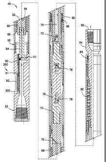
allow
production fluid to flow into the casing and up to the surface of the well. In
recent
years, oil field technology has increasingly used sidetracking or directional
drilling to
further exploit the resources of productive zones. In sidetracking, an exit,
such as a
slot or window, is cut in a steel cased wellbore typically using a mill, where
drilling is
continued through the exit at angles to the vertical wellbore. In directional
drilling, a
wellbore is cut in strata at an angle to the vertical shaft typically using a
drill bit. The
1
CA 02722612 2010-10-26
WO 2009/137537 PCT/US2009/042918
mill and the drill bit are rotary cutting tools having cutting blades or
surfaces typically
disposed about the tool periphery and in some models on the tool end.
SUMMARY OF THE INVENTION
[0004]
Embodiments of the present invention generally relate to signal operated
tools for milling, drilling, and/or fishing operations. In one embodiment, a
mud motor
for use in a wellbore includes: a
stator; a rotor, the stator and rotor operable to
rotate the rotor in response to fluid pumped between the rotor and the stator;
and a
lock. The lock is operable to: rotationally couple the rotor to the stator in
a locked
position, receive an instruction signal from the surface, release the rotor in
an
unlocked position, and actuate from the locked position to the unlocked
position in
response to receiving the instruction signal.
[0005] In
another embodiment, a setting tool for setting an anchor includes a
tubular housing having a port formed through a wall thereof; a piston disposed
in the
housing and operable to inject fluid through the port; and an actuator. The
actuator is
operable: to receive an instruction signal from the surface, and to drive the
piston in
response to receiving the instruction signal.
[0006] In
another embodiment, a method of forming an opening in a wall of a
wellbore includes deploying a drill string and a bottom hole assembly (BHA)
into the
wellbore. The BHA includes a bit, mud motor, an orientation sensor, a setting
tool, a
whipstock, and an anchor. The method further includes orienting the whipstock
while
injecting drilling fluid through the motor sufficient to operate the
orientation sensor.
The motor is in a locked position. The method further includes sending an
instruction
signal to the setting tool, thereby setting the anchor.
[0007] In
another embodiment, a data sub for use in a wellbore includes a tubular
housing having a bore formed therethrough; one or more sensors disposed in the
housing; and a transmitter disposed in the housing and operable to transmit a
measurement from the sensor to the surface.
[0008] In
another embodiment, a method of transmitting data from a depth in a
wellbore distal from the surface to the surface includes: measuring a
parameter using
a data sub interconnected in a tubular string disposed in the wellbore. The
data sub is
at the distal depth. The method further includes transmitting the measurement
from
2
CA 02722612 2010-10-26
WO 2009/137537 PCT/US2009/042918
the data sub to a repeater sub interconnected in the tubular string. The
repeater sub
is at a depth between the distal depth and the surface. The method further
includes
retransmitting the measurement from the repeater sub to the surface.
[0009] In another embodiment, a jar for use in a wellbore includes: a
tubular
mandrel; a tubular housing; a fluid chamber formed between the housing and the
mandrel; a piston operable to increase pressure in the chamber in response to
longitudinal displacement of the mandrel relative to the housing; a valve
operable to
open the chamber in response to a predetermined longitudinal displacement of
the
mandrel relative to the housing; and a lock. The lock is operable to:
longitudinally
couple the mandrel to the housing in a locked position, receive an instruction
signal
from the surface, release the mandrel in an unlocked position, and actuate
from the
locked position to the unlocked position in response to receiving the
instruction signal.
[0010] In another embodiment, a jar for use in a wellbore includes: a
tubular
mandrel; a tubular housing; and a valve. The valve is: longitudinally coupled
to the
mandrel, operable to at least substantially restrict fluid flow through the
jar in a closed
position, thereby exerting tension on the mandrel, and operable to open in
response
to a predetermined longitudinal displacement of the mandrel relative to the
housing.
The jar further includes a lock operable to: longitudinally couple the mandrel
to the
housing in a locked position, receive an instruction signal from the surface,
release
the mandrel in an unlocked position, and actuate from the locked position to
the
unlocked position in response to receiving the instruction signal.
[0011] In another embodiment, a fishing tool for engaging a tubular stuck
in a
wellbore includes: a tubular housing having an inclined surface; a grapple
having an
inclined surface longitudinally movable along the inclined surface of the
housing,
thereby radially moving the grapple between a retracted position and an
engaged
position; and an actuator. The actuator is operable to: longitudinally
restrain the
grapple in the released position, receive an instruction signal from the
surface, and
longitudinally move the grapple from the released position to the engaged
position in
response to receiving the instruction signal.
[0012] In another embodiment, a method of freeing a fish stuck in a
wellbore
includes deploying a fishing assembly into the wellbore. The fishing assembly
includes a workstring, a jar, and a fishing tool, and the jar is in a locked
position. The
3
CA 02722612 2010-10-26
WO 2009/137537 PCT/US2009/042918
method further includes engaging the fishing tool with the fish; sending an
instruction
signal from the surface to the fishing tool, thereby engaging a grapple of the
fishing
tool with the fish; sending a second instruction signal from the surface to
the jar,
thereby unlocking the jar; and firing the jar, thereby exerting an impact on
the fish.
[0013] In
another embodiment, a disconnect tool for use in a string of tubulars
includes: a tubular mandrel; a tubular housing; a latch longitudinally
coupling the
housing and the mandrel; a lock operable to engage the latch in a locked
position and
disengage from the latch in a released position; and an actuator. The actuator
is
operable to: receive an instruction signal from the surface, and move the lock
to the
released position in response to receiving the instruction signal.
[0014] In
another embodiment, a disconnect tool for use in a string of tubulars
includes: a tubular mandrel; a tubular housing; a latch operable to
longitudinally
couple the housing and the mandrel in an engaged position. The latch is
fluidly
operable to a disengaged position. The disconnect further includes a valve
operable
to: receive an instruction signal from the surface, and open in response to
receiving
the instruction signal, thereby providing fluid communication between a bore
of the
housing and the latch.
[0015] In
another embodiment, a disconnect tool for use in a string of tubulars
includes: a tubular mandrel having a threaded inner surface; a tubular housing
having
a plurality of openings formed radially through a wall thereof; an arcuate dog
disposed
in each opening, each dog having an inclined inner surface and portion of a
thread
corresponding to the mandrel thread and radially movable between an engaged
position and a disengaged position. The thread portion engages the mandrel
thread
in the engaged position, thereby longitudinally and rotationally coupling the
housing
and the mandrel. The disconnect further includes a tubular sleeve having an
inclined
outer surface operable to engage with the inclined inner surface of each dog.
[0016] In
another embodiment, a method of drilling a wellbore includes: deploying
a drilling assembly in the wellbore. The drilling assembly includes a drill
string, a
disconnect tool, and a drill bit.
The method further includes injecting drilling fluid
through the drilling assembly and rotating the bit, thereby drilling the
wellbore. The
method further includes sending an instruction signal from the surface,
thereby
operating the disconnect tool and releasing the drill bit from the drill
string.
4
CA 02722612 2010-10-26
WO 2009/137537 PCT/US2009/042918
[0017] In another embodiment, a drilling assembly includes a tubular drill
string; a
drill bit longitudinally coupled to an end of the drill string; and a
plurality of data subs
interconnected with the drill string. Each data sub includes a strain gage
oriented to
measure torque or longitudinal load; and a transmitter.
[0018] In another embodiment, a method of determining a freepoint of a
drilling
assembly stuck in a wellbore, the drilling assembly including a drill string
and a
plurality of data subs interconnected with the drill string. The method
includes:
exerting a torque and/or tension on the stuck drilling assembly from the
surface;
measuring a response of the drilling assembly to the torque and/or tension
using the
data subs; transmitting the measured response from the data subs to the
surface; and
determining a freepoint of the drilling assembly using the transmitted
response.
[0019] In another embodiment, a cutter for use in a wellbore includes: a
tubular
housing having one or more openings formed through a wall thereof; one or more
blades, each blade pivoted to the housing and rotatable relative thereto
between an
extended position and a retracted position. Each blade extends through the
opening
in the extended position. The cutter further includes a piston operable to
move the
blades to the extended position in response to injection of fluid
therethrough; and a
stop. The stop is operable: receive a position signal from the surface, and
move to a
set position in response to the signal.
[0020] In another embodiment, a cutter for use in a wellbore includes: a
tubular
housing having a one or more openings formed through a wall thereof; one or
more
blades, each blade pivoted to the housing and rotatable relative thereto
between an
extended position and a retracted position. Each blade extends through a
respective
opening in the extended position. The cutter further includes a mandrel
operable to
move the blades to the extended position; and an actuator. The actuator is
operable
to: receive a position signal from the surface, and move the mandrel to a set
position
in response to the position signal, thereby at least partially extending the
blades.
[0021] In another embodiment, a method of cutting or milling a tubular
cemented
to the wellbore includes deploying a cutting assembly into the wellbore. The
cutting
assembly includes a workstring and a cutter. The method further includes
sending an
instruction signal to the cutter, thereby extending one or more blades of the
cutter;
and rotating the cutter, thereby milling or cutting the tubular.
CA 02722612 2010-10-26
WO 2009/137537 PCT/US2009/042918
BRIEF DESCRIPTION OF THE DRAWINGS
[0022] So
that the manner in which the above recited features of the present
invention can be understood in detail, a more particular description of the
invention,
briefly summarized above, may be had by reference to embodiments, some of
which
are illustrated in the appended drawings. It is to be noted, however, that the
appended drawings illustrate only typical embodiments of this invention and
are
therefore not to be considered limiting of its scope, for the invention may
admit to
other equally effective embodiments.
[0023]
FIG. 1 is a schematic cross sectional view of a drill string and bottomhole
assembly (BHA), according to one embodiment of the present invention.
[0024]
FIG. 2A is a cross sectional view of a motor of the BHA. FIG. 2B is a cross
section of a lock of the motor in the unlocked position. FIG. 20 is a detailed
side view
of a portion of the BHA. FIG. 2D is a cross section of a setting tool of the
BHA.
[0025]
FIG. 3A illustrates a radio-frequency identification (RFID) electronics
package. FIG. 3B illustrates an active RFID tag and a passive RFID tag.
[0026]
FIG. 4A illustrates the BHA after the anchor is set with the whipstock in the
proper orientation. FIG. 4B illustrates the mills cutting a window through the
casing.
[0027]
FIG. 5 is a schematic of a fishing assembly deployed in a wellbore to
retrieve a fish stuck in the wellbore, according to another embodiment of the
present
invention. FIG. 5A is a cross section of a data sub of the fishing assembly.
[0028]
FIG. 6 is a cross section of a jar of the fishing assembly. FIG. 6A is an
enlarged portion of FIG. 6. FIG. 6B is a cross section of FIG. 6A. FIGS. 60
and 6D
illustrate an alternative embodiment of the piston. FIGS. 6E and 6F illustrate
an
alternative embodiment of the piston.
[0029]
FIG. 7 is a cross section of an alternative vibrating jar 700. FIG. 7A is an
enlarged view of the latch. FIG. 7B is a further enlarged view of the latch in
the
unlocked position. FIG. 70 is a further enlarged view of the latch in the
unlocked
position.
[0030]
FIG. 8A is a cross section of the overshot in a set position. FIG. 8B is a
cross section of the overshot in a released position.
6
CA 02722612 2013-03-06
[0031] FIG. 9 is a schematic view of a wellbore having a casing and a
drilling assembly,
according to another embodiment of the present invention.
[0032] FIG. 10A is a cross section of the disconnect in a locked position.
FIG. 10B is a
cross section of the disconnect in a released position. FIG. 10C is a cross
section of a portion
of an alternative disconnect in a locked position. FIG. 10D is a cross section
of alternative
disconnect in a locked position. FIG. 10E is a cross section of the disconnect
in a released
position. FIGS. 1OF and 10G are enlarged portions of FIGS. 10D and 10E. FIG.
10H is a
cross section of a portion of an alternative disconnect including an
alternative actuator in a
locked position. FIG. 101 is a cross section of alternative disconnect in a
locked position. FIG.
10J is a cross section of the disconnect in a released position.
[0033] FIG. 11 is a schematic of a drilling assembly, according to another
embodiment of
the present invention.
[0034] FIG. 12A is a cross section of a casing cutter in a retracted
position, according to
another embodiment of the present invention. FIG. 12B is a cross section of
the casing cutter
in an extended position. FIG. 12C is an enlargement of a portion of FIG. 12A.
FIG. 12D is a
cross section of a portion of an alternative casing cutter including an
alternative blade stop in a
retracted position. FIG. 12E is a cross section of a portion of an alternative
casing cutter
including a position indicator instead of a blade stop. FIG. 12F is a cross
section of an
alternative casing cutter in an extended position.
[0035] FIG. 13A is a cross section of a section mill 1300 in a retracted
position, according
to another embodiment of the present invention. FIG. 13B is an enlargement of
a portion of
FIG. 13A. FIG. 13C illustrates two section mills connected, according to
another embodiment
of the present invention.
DETAILED DESCRIPTION
[0036] FIG. 1 is a schematic cross sectional view of a drill string 15 and
bottomhole
assembly (BHA) 100, according to one embodiment of the present invention. The
wellbore 10
is drilled through a surface 11 of the earth to establish a wellbore 10. The
wellbore 10 may be
cased with a casing 14. The casing 14 may be cemented 12 into the wellbore 10.
A reel 13 is
disposed adjacent the wellbore 10 and contains a quantity of tubing, such as
coiled tubing 15.
Alternatively, the drill string 15
7
CA 02722612 2013-03-06
may be joints of drill pipe connected with threaded connections. The coiled
tubing 15 typically
does not rotate to a significant degree within the wellbore.
[0037] The BHA 100 may be longitudinally and rotationally coupled to the
coiled tubing 15,
such as with a threaded or flanged connection. Various components can be
coupled to the
coiled tubing 15 as described below beginning at the lower end of the
arrangement. The BHA
100 may include an orienter 34, a measurement while drilling tool (MWD) 32, a
mud motor 48,
a stabilizer 28, a setting tool 250, a spacer mill 26, and a lead mill 22, a
whipstock 20, and an
anchor 38. Each of the BHA components longitudinally and rotationally coupled,
such as with
a threaded or flanged connection.
[0038] The anchor 38 may be a bridge plug or packer and may be selectively
expanded by
operation of the setting tool 250. The whipstock 20 may include an elongated
tapered surface
that guides the bit 22, outwardly toward casing 14. The whipstock 20 may be
longitudinally and
rotationally coupled to the lead mill 22 by one or more frangible members,
such as shear
screws 24. The spacer mill 26 may be operable to further define the hole or
exit created by the
lead mill. Alternatively, a hybrid mill/drill bit capable of milling an exit
and continuing to drill into
the formation may be used instead of the lead mill. An exemplary hybrid bit is
disclosed in U.S.
Pat. Ser. No. 5,887,668. The stabilizer 28 may have extensions protruding from
the exterior
surface to assist in concentrically retaining the BHA 100 and in the wellbore
10. The motor 48
may be operated by injection of drilling fluid, such as mud, therethrough to
rotate the mills 22,
26 while the coiled tubing 15 remains relatively rotationally stationary.
[0039] As discussed below, the motor 48 may be selectively operable. The
MWD 32 also
be operated by the injection of drilling mud therethrough to provide feedback
to equipment
located at the surface 11, such as by pulsing the flow of the mud. The
orienter 34 may be
operable to incrementally angular rotate the whipstock 20 in a certain
direction. The orienter
34 may be operated by starting injection of drilling mud therethrough and
stopping mud
injection after a predetermined increment of time. Each pulse of mud indexes
the orienter a
predetermined increment, such as 15-30 degrees. Thus, the orienter 34 can
rotate the
arrangement containing the whipstock to a desired orientation within the
wellbore, while the
position measuring member 32 provides feedback to determine the orientation.
Alternatively, if
drill pipe is used
8
CA 02722612 2013-03-06
. ,
instead of coiled tubing, the whipstock may be oriented by rotating the drill
string or using the
orienter, thereby making the orienter optional.
[0040] The motor 48 allows flow without substantial rotation at a
first flow rate and/or
pressure to allow sufficient flow through the orienter 34 and the position
measuring member 32
without actuation of the motor. The flow in the tubing member through the
orienter, position
measuring member and motor is then exhausted through ports in the end mill and
flows
outwardly and then upwardly through the wellbore 10 back to the surface 11.
Flow through or
around the motor 48 allows the reduction of at least one trip in setting the
anchor 18 and
starting to drill the exit in the wellbore 10.
[0041] FIG. 2A is a cross sectional view of the motor 48. FIG. 2B is a
cross section of the
lock 200 in the unlocked position. The motor 48 may be a progressive cavity
motor and include
a top sub 50 having a fluid inlet 52, an output shaft 54 having a fluid outlet
56, and a power
section 58 disposed therebetween. The power section 58 may include a stator 60
circumferentially disposed about a rotor 62. The rotor 62 may have a hollow
bypass 64
disposed therethrough that is fluidly coupled from the inlet 52 to the outlet
56. An inlet 66 of
the power section 58 of the motor 48 may allow fluid to flow into a
progressive cavity created
between the stator 60 and the rotor 62 as the rotor rotates about the stator
and to exit an outlet
68 of the power section.
[0042] The stator 60 may include a housing and an elastomeric member
molded thereto.
An outer surface of the rotor 62 may form a plurality of lobes extending
helically along the
rotor. An inner surface of the stator may form a plurality of lobes extending
helically along the
stator. The number of stator lobes may be one more than the number of rotor
lobes. The stator
may be conventional or even-walled. A conventional stator may have the lobes
formed by the
elastomeric member and an even-walled stator may have the lobes formed by the
housing and
the elastomeric member, resulting in a thinner elastomeric member than the
conventional
stator. Fluid flowing from the inlet through the power section may drive the
rotor to rotate and
precess, thereby forming a progressive cavity that progresses from the inlet
to the outlet as the
rotor rotates.
[0043] An annulus 70 downstream of the outlet 68 is created between
the inner wall of the
motor 48 and various components disposed therein, which provide a flow
9
CA 02722612 2010-10-26
WO 2009/137537 PCT/US2009/042918
path for the fluid exiting the outlet 68. A transfer port 72 is fluidly
coupled from the
annulus 70 to a hole 74 disposed in the output shaft 54 and then to the output
56. A
restrictive port 75 can be formed between the hollow cavity 64 and the annulus
70 to
fluidly couple the hollow cavity 64 to the annulus 70.
[0044] Because the rotor precesses within the stator, an articulating shaft
76 may
be disposed between the rotor 62 and the output shaft 54, so that the output
shaft 54
can rotate circumferentially within the motor 48. The articulating shaft 76
can include
one or more knuckle joints 78 that allow the rotor to precess within the
stator with the
necessary degrees of freedom. A bearing 80 can be disposed on an upper end of
an
output shaft 54 and a lower bearing assembly 82 can be disposed on a lower end
of
an output shaft 54. One or more seals, such as seals 84, 86, assist in sealing
fluid
from leaking through various joints in the downhole motor 48.
[0045] As discussed above, the motor 48 may be selectively operated. The
motor
48 may further include a lock 200 disposed in a chamber formed in the top sub
52.
The chamber may be sealed (not shown) from the wellbore and a bore of the top
sub
52. The lock 200 may include a key 90, a shaft 91, and an actuator, such as a
solenoid 92. The key 90 and shaft 91 may be rotationally coupled to the top
sub 52.
A stem 94 may be longitudinally and rotationally coupled to the rotor 62, such
as by a
threaded connection. The lock 200 may be operable between a locked position
and
an unlocked position. The key 90 may be received by a keyway formed through a
head of the stem. Engagement of the key 90 with the keyway may rotationally
couple the rotor 62 to the top sub 52, thereby preventing operation of the
motor 48. A
valve, such as a flapper 93, may be longitudinally coupled to the stem 94. The
flapper 93 may be biased toward a closed position, such as by a torsion
spring, where
the flapper 93 may cover a top of the bypass 64, thereby preventing fluid flow
from
the top sub bore into the bypass. The flapper 93 may be held in the open
position by
engagement of the key 90 with an arm rotationally coupled to the flapper 93.
Disengagement of the key 90 from the keyway may release the rotor 62 and the
flapper 93, thereby allowing the motor 48 to operate and sealing the bypass
64.
[0046] Alternatively, the flapper and the bypass may be omitted. In
this
alternative, leakage through the mud motor may supply the necessary fluid flow
to
allow operation of the orienter 34 and the MWD tool 32.
CA 02722612 2010-10-26
WO 2009/137537 PCT/US2009/042918
[0047]
FIG. 3A illustrates a radio-frequency identification (RFID) electronics
package 300. FIG. 3B illustrates an active RFID tag 350a and a passive RFID
tag
350p. The lock 200 may further include the electronics package 300. The
electronics
package 300 may communicate with a passive RFID tag 350p or an active RFID tag
350a. Either of the RFID tags 350a,p may be individually encased and dropped
or
pumped through the coiled tubing string. Alternatively, either of the RFID
tags may be
embedded in a ball (not shown) for seating in a ball seat of a tool, a plug,
bar or some
other device used to initiate action of a downhole tool.
[0048]
The RFID electronics package 300 may include a receiver 302, an amplifier
304, a filter and detector 306, a transceiver 308, a microprocessor 310, a
pressure
sensor 312, battery pack 314, a transmitter 316, an RF switch 318, a pressure
switch
320, and an RF field generator 322. If the active RFID tag 350a is used, the
components 316-322 may be omitted.
[0049] If
a passive tag 350p is used, once the motor lock 200 is deployed to a
sufficient depth in the wellbore, the pressure switch 320 may close. The
pressure
switch 320 may remain open at the surface to prevent the electronics package
300
from becoming an ignition source. The microprocessor may also detect
deployment
in the wellbore using pressure sensor 312. The microprocessor 310 may delay
activation of the transmitter for a predetermined period of time to conserve
the battery
pack 314. The microprocessor may then begin transmitting a signal and
listening for
a response. Once the tag 350p is deployed into proximity of the transmitter
316, the
passive tag 350p may receive the signal, convert the signal to electricity,
and transmit
a response signal. The electronics package 300 may receive the response
signal,
amplify, filter, demodulate, and analyze the signal. If
the signal matches a
predetermined instruction signal, then the microprocessor 310 may activate the
motor
lock 200.
[0050] If
the active tag 350a is used, then the tag 350a may include its own
battery, pressure switch, and timer so that the tag 350a may perform the
function of
the components 316-322.
[0051]
Further, either of the tags 350a,p may include a memory unit (not shown)
so that the microprocessor may send a signal to the tag and the tag may record
the
signal. The signal may then be read at the surface 11. The signal may be
11
CA 02722612 2010-10-26
WO 2009/137537 PCT/US2009/042918
confirmation that a previous action was carried out or a measurement by a
sensor,
such as pressure, temperature, torque, and/or longitudinal load.
[0052]
Alternatively, instead of RFID, the electronics package 300 may be
configured to receive mud pulses from the surface. Alternatively, instead of
RFID, the
electronics package may include an electromagnetic (EM) receiver or
transceiver (not
shown) or an acoustic receiver or transceiver. An EM telemetry system is
discussed
in US Pat. No. 6,736,210, which is hereby incorporated by reference in its
entirety.
[0053]
Returning to FIGS. 2A and 2B, once the microprocessor 310 detects the
one of the RFID tags 350a,p with the correct instruction signal, the
microprocessor
310 may supply electricity from the battery 314 to the solenoid 92, thereby
longitudinally retracting the shaft 91 and the key 93 from the stem 94 and
allowing
operation of the motor 48 and closing of the bypass 64.
[0054]
The motor lock 200 may further include a position sensor 95, such as a coil
of wire wound around an inner surface of the solenoid 92. The position sensor
95
may be operable to detect a position of the shaft 91 to determine if the key
has seated
or unseated in to/from the keyway. The coil 95 may determine the position of
the
shaft 91 via electromagnetic communication with the shaft. Alternatively, a
proximity
switch may be used instead of the position sensor 95. The position sensor 95
may be
in communication with the microprocessor 310 so that the microprocessor may
monitor the position of the shaft 91, thereby knowing when to cease supplying
electricity to the solenoid. The lock 200 may further include a mechanical
latch (not
shown) to retain the shaft and key in the unlocked position. For the limit
switch
alternative, the limit switch may be incorporated into the mechanical latch.
When
actuating the key between the positions, the microprocessor may utilize the
position
sensor 95 to conserve battery life by supplying electricity at a first power
level to the
solenoid to determine if the shaft moves. If
the shaft does not move, the
microprocessor may then supply electricity to the solenoid at a second
increased
power level and so on until the shaft moves. Further, once the instruction
signal has
been sent, the surface may send a second tag including a memory unit that
requests
a status report from the microprocessor, such as confirmation that the motor
has been
successfully unlocked, what power level was required to unlock the motor, an
error
log if the motor was not successfully unlocked, and/or a charge level of the
battery.
The microprocessor may encode the requested data to the tag using the
transmitter
12
CA 02722612 2010-10-26
WO 2009/137537 PCT/US2009/042918
316. The tag may return to surface via an annulus formed between the drill
string and
the casing.
[0055] FIG. 20 is a detailed side view of a portion of the BHA 100. The
setting tool
250 may be in fluid communication with the anchor 38 via a control line 205.
The
anchor 38 may be retrievable after it is set or made from a drillable
material. The
anchor 38 may include a mandrel, a piston, slips, a packing element, and a
cone.
Fluid pressure supplied to the piston from the setting 250 tool may drive the
piston
longitudinally along the mandrel, thereby compressing the packing element
radially
outward against the casing and pushing the slips over the cone (or vice
versa),
thereby radially moving the slips outward against the casing. The whipstock 20
may
be releasably connected to the anchor 38 so that the whipstock may be
retrieved.
[0056] FIG. 2D is a cross section of the setting tool 250. The setting tool
may
include a housing 255, an actuator 260, a trigger 265, a piston 270, a
cylinder 275, a
biasing member, such as a spring 280, a rod 285, a sleeve 290, and the
electronics
package 300. The housing 255 may be tubular and include threaded couplings
formed at each longitudinal end thereof. The sleeve 290 may be disposed in the
housing 255 and longitudinally and rotationally coupled thereto. The sleeve
290 may
house the actuator 260, the rod 285, the piston 270, the spring 280, and the
cylinder
275. The sleeve 290, the cylinder 275, and the housing 255 may each have a
flow
port formed therethrough providing fluid communication between the cylinder
275 and
the control line 205. The cylinder 275 may be filled up to the piston 270 with
a
hydraulic fluid, such as oil. The piston 270 may be housed in the cylinder,
biased
toward a lower end of the cylinder 275 by the spring 280.
[0057] The rod 285 may be longitudinally coupled to the cylinder 275, such
as by a
threaded connection. The rod 285 may be longitudinally restrained by a trigger
265.
The actuator 260 may include a solenoid for radially moving the trigger 265.
The
actuator 260 may be longitudinally coupled to the sleeve 290. In operation,
when it is
desired to set the anchor 38, one of the tags 350a,p may be dropped or pumped
through a bore of the housing 255 and the sleeve 290. The electronics package
300
may detect an instruction signal from the tag 350a,p. The microprocessor 310
may
then supply electricity to the actuator 260, thereby radially moving the
trigger 265
outward and releasing the rod. The spring 280 may then push the piston 270 and
the
13
CA 02722612 2010-10-26
WO 2009/137537 PCT/US2009/042918
rod 285 toward the lower end of the cylinder 275, thereby driving the anchor
piston via
the hydraulic fluid.
[0058] Alternatively, a pump may replace the piston and cylinder.
Alternatively,
instead of a spring, an upper end of the piston may be exposed to wellbore
pressure
or a pressurized gas chamber, such as nitrogen.
[0059] FIG. 4A illustrates the BHA 100 after the anchor 38 is set with the
whipstock 20 in the proper orientation. In operation, mud may be pumped down
the
coiled tubing 15 and into inlet 52 of the top sub 50. The mud flow may
continue into
the bypass 64 in the rotor 62 and through port 75, into the annulus 70, and
eventually
through the output 56 of the output shaft 54. The mud flow may exit the BHA
100 via
ports formed through the mill 22. The flow through the bypass 64 may provide
the
necessary flow rate to operate the orienter 34 and the MWD tool 32. Once the
whipstock 20 is oriented, an RFID tag 350a,p may be dropped/pumped through the
coiled tubing to the setting tool electronics package. The tag 350a,p may
include the
appropriate instruction signal for the setting tool 250 to operate. The
setting tool 250
may receive the instruction signal from the tag 350a,p and set the anchor 38.
[0060] FIG. 4B illustrates the mills cutting a window 36 through the casing
14.
Since the tags may be encoded with unique signals, a second tag 350a,p may
then
be dropped to generate a second signal for the motor lock 200. Alternatively,
the
motor lock 200 may also receive the setting tool instruction signal and delay
operation
for a predetermined period of time sufficient for the setting tool to set the
anchor. The
motor lock 200 may then unlock the motor and close the bypass 64. The motor 48
may then exert torque on the mill assembly, thereby shearing the screws 24 and
the
control line 205 and releasing the whipstock 20. Alternatively, the screws 24
may be
sheared before unlocking the motor by setting weight of the drill string down
on to the
BHA 100 from the surface, thereby also testing for setting of the anchor. The
BHA
100 may then be lowered and the whipstock 20 may guide the rotating mills
22,26 into
engagement with the casing 14. The mills 22,26 may then form the window 36.
[0061] Alternatively, the motor 48 may be used as a backup motor to a
primary
drilling motor in a drill string. The motor 48 may remain locked if and until
the primary
motor fails. A tag 350a,p may then be dropped unlocking the motor 48 and
drilling
may be continued without tripping the drill string to replace the primary
motor.
14
CA 02722612 2013-03-06
Alternatively, the motor 48 may be disposed in a directional drill string
including a bit motor, a
drill bit, and a bent sub. The bit motor may rotate the drill bit and the
motor 48 may selectively
rotate the bent sub, the drill bit, and the bit motor to switch between rotary
and slide drilling.
[0062] Alternatively, the motor lock 200 may be used with a conventionally
set anchor 38.
Alternatively, the setting tool 250 may be used with a conventional mud motor
and an
alternative MWD tool which utilizes electromagnetic telemetry to communicate
to the surface.
Alternatively, the setting tool 250 may be used with a shear-pin locked motor
or a motor with a
choked bypass and the mud operated MWD tool 32.
[0063] FIG. 5 is a schematic of a fishing assembly 500 deployed in a
wellbore 501 to
retrieve a fish 525 stuck in the wellbore, according to another embodiment of
the present
invention. The fishing assembly 500 may include a workstring 505, a slinger
510, drill collars
515, a jar 600, a bumper sub 520, a data sub 550, and an overshot 800. The
fish 525 may be
a lower portion of a drill string. The components of the fishing assembly may
each be
longitudinally and rotationally coupled, such as with threaded connections.
The workstring 505
may be coiled tubing or drill pipe. The upper portion of the drill string (not
shown) may have
been removed by a freepoint operation, by operation of a release sub
(discussed below), or
the drill string may have separated by failure and the upper portion may have
been simply
retrieved to the surface. Alternatively, instead of the overshot 800, the
fishing assembly 500
may include any other gripper for engaging the fish, such as a spear, wire
rope grapple, wire
rope spear, or a tapper tip.
[0064] Additionally, the fishing assembly may include an overpull generator
(not shown),
Such a generator is discussed and illustrated in U.S. Pat. App. No.
12/023,864, filed Jan. 31,
2008. The overpull generator may be operable to create a force which is used
by the other
components in the fishing assembly 500 to dislodge the fish 525. The energy
may be
generated by moving a piston rod of the overpull generator between an extended
position and
a retracted position. The overpull generator may include a plurality of
pistons that activate due
to a pressure drop caused by a flow restriction through the overpull
generator.
CA 02722612 2010-10-26
WO 2009/137537 PCT/US2009/042918
[0065] FIG. 5A is a cross section of the data sub 550. The data sub 550 may
include an upper adapter 551, a cover 552, a housing 553, the electronics
package
300, a pressure and temperature (PT) sub 554, a torque sub 555, a lower
adapter
556, and a mud pulser 557.
[0066] The adapters 551,556 may each be tubular and have a threaded
coupling
formed at a longitudinal end thereof for connection with other components of
the
fishing assembly 500. The housing 553 may be disposed between the upper
adapter
551 and the PT sub 554. The PT sub 554 may be longitudinally and rotationally
coupled to the cover 552, such as with fasteners (not shown) and sealed, such
as
with one or more o-rings. The cover 552 may be longitudinally and rotationally
coupled to the upper adapter 551, such as with fasteners (not shown) and
sealed,
such as with one or more o-rings. The torque sub 555 may be longitudinally and
rotationally coupled to the PT sub 554 with a threaded connection. The lower
adapter
556 may be longitudinally and rotationally coupled to the torque sub 555 with
a
threaded connection.
[0067] The PT sub 554 may include a temperature sensor 560t and a pressure
sensor 560p. The pressure sensor 560p may be in fluid communication with a
bore of
the PT sub 554 via a first port and in fluid communication with the wellbore
501 via a
second port. The sensors 560p,t may be in data communication with the
microprocessor 310 by engagement of contacts formed at a bottom of the housing
with corresponding contacts formed at a top of the PT sub 554. The sensors
560p,t
may also receive electricity via the contacts.
[0068] The torque sub 555 may include one or more sensors, such as strain
gages
565a,b bonded to an inner surface thereof. The strain gage 565a may be
oriented to
measure longitudinal strain and the strain gage 565b may be oriented to
measure
torsional strain. The strain gages 565a,b may be in data and electrical
communication with the microprocessor via contacts (not shown) or one or more
wires (not shown) extending through the PT sub 554. The torque sub 555 may
further
include one or more accelerometers for measuring shock and/or vibration.
Alternatively (discussed below) the data sub 550 may be disposed in a drilling
assembly and the data sub may include one or more gyroscopes for measuring
orientation of a drill bit. Additionally, the data sub may include a camera
(i.e., optical
or infrared) for recording downhole video. Additionally, the data sub 550 may
include
16
CA 02722612 2010-10-26
WO 2009/137537 PCT/US2009/042918
a rotation sensor for measuring rotation and/or rotational velocity of the
data sub.
Additionally, the data sub 550 may include a circulation valve and an actuator
operable by the microprocessor.
[0069]
The mud pulser 557 may be disposed between PT sub 554 and the torque
sub 555. The mud pulser 557 may be in electrical and data communication with
the
microprocessor 310 via contacts or wires (not shown) extending through the PT
sub
554. The mud pulser 557 may include a valve (not shown) and an actuator for
variably restricting flow through the pulser, thereby creating pressure pulses
in drilling
fluid pumped through the mud pulser. The mud pulses may be detected at the
surface, thereby communicating data from the microprocessor to the surface.
The
mud pulses may be positive, negative, or sinusoidal.
[0070]
Alternatively, an electromagnetic (EM) gap sub may be used instead of the
mud pulser, thereby allowing data to be transmitted to the surface using EM
waves.
Alternatively, an RFID tag launcher may be used instead of the mud pulser. The
tag
launcher may include one or more RFID tags. The microprocessor 310 may then
encode the tags with data and the launcher may release the tags to the
surface.
Alternatively, an acoustic transmitter may be used instead of the mud pulser.
Alternatively, and as discussed above, instead of the mud pulser RFID tags may
be
periodically pumped through the data sub and the microprocessor may send the
data
to the tag. The tag may then return to the surface via an annulus formed
between the
workstring and the wellbore. The data from the tag may then be retrieved at
the
surface. Alternatively, and as discussed above, instruction signals may be
sent to the
electronics package using mud pulses, EM waves, or acoustic signals instead of
RFID tags. Alternatively, the fishing assembly may be wired so that
communication
from the surface to the data sub and vice versa may use the wire.
Additionally, the
data sub may be used with any of the tools disclosed herein.
[0071] In
operation, when it is desired to activate the data sub 550, an RFID tag
350a,p may be pumped/dropped through the workstring 505 to the antenna 302,
thereby conveying an instruction signal from the surface. The tag 350a,p may
also be
used to operate the jar 600 and/or overshot 800 (discussed below).
The
microprocessor 310 may then begin recording data from the PT sub 554 and the
torque sub 555 and transmitting the data to the surface using the mud pulser
557.
The surface operator may then receive real-time data during the fishing
operation.
17
CA 02722612 2010-10-26
WO 2009/137537 PCT/US2009/042918
Alternatively, the electronics package 300 may include a memory unit (not
shown)
and the microprocessor 310 may record data before the instruction signal is
sent and
begin transmitting data after the instruction is sent. Alternatively, the
microprocessor
310 may filter the data and transmit only certain measurements, i.e.,
maximums, to
conserve bandwidth.
[0072] Instead of or in addition to receiving an instruction signal from
the surface,
the microprocessor 310 may be programmed to wait for and detect a trigger
event
before transmitting data. For example, the trigger event may be a tensile load
that
surpasses a predetermined value. Another example of a trigger event is an
increase
in pressure, or several increases in pressure that prescribe to a specified
pattern.
This pattern may be interpolated by the microprocessor to process a different
set of
data, start or stop recording/ transmitting, or perform a specified action.
[0073] For deeper wells, the fishing assembly 500 may further include a
signal
repeater (not shown) to prevent attenuation of the transmitted mud pulse. The
repeater may detect the mud pulse transmitted from the mud pulser 557 and
include
its own mud pulser for repeating the signal. As many repeaters may be disposed
along the workstring as necessary to transmit the data to the surface, i.e.,
one
repeater every five thousand feet. These repeaters may be adapted to perform
dual
functions and in one embodiment may be stabilizers on the workstring (see FIG.
19 of
the '511 provisional). Each repeater may also be a data sub and add its own
measured data to the retransmitted data signal. If the mud pulser is being
used, the
repeater may wait until the data sub is finished transmitting before
retransmitting the
signal. The repeaters may be used for any of the mud pulser alternatives,
discussed
above. Repeating the transmission may increase bandwidth for the particular
data
transmission. The increased bandwidth may allow high demand transmissions,
such
as video.
[0074] Alternatively, multiple subs may be deployed in a workstring or
drill string.
An RFID tag including a memory unit may be dropped/pumped through the data
subs
and record the data from the data subs until the tag reaches a bottom of the
data
subs. The tag may then transmit the data from the upper subs to the bottom sub
and
then the bottom sub may transmit all of the data to the surface.
18
CA 02722612 2010-10-26
WO 2009/137537 PCT/US2009/042918
[0075] FIG. 6 is a cross section of the jar 600. FIG. 6A is an enlarged
portion of
FIG. 6. FIG. 6B is a cross section of FIG. 6A. The jar 600 may include a
mandrel
605, a housing 610, a hammer 607, one or more sleeves, such as upper sleeve
620a
and lower sleeve 620b, a piston 650, a traveling valve 625, a biasing member,
such
as a spring 630, a balance piston 635, and a balance spring 640.
[0076] The mandrel 605 and the housing 610 may each be tubular and each
have
a threaded coupling formed at a longitudinal end thereof for connection with
other
components of the fishing assembly 500. To facilitate manufacture and
assembly,
each of the mandrel 605 and housing 610 may include a plurality of
longitudinal
sections, each section longitudinally and rotationally coupled, such as by
threaded
connections, and sealed, such as by 0-rings. The mandrel 605 and the housing
610
may be rotationally coupled by engagement of longitudinal splines 605s, 610s
formed
along an outer surface of the mandrel and an inner surface of the housing. The
housing 610 and the mandrel 605 may be longitudinally coupled in a locked
position
by closure of a valve in the piston 650 (discussed below). In an unlocked
position, the
housing 610 and the mandrel 605 may be longitudinally movable relative to each
other until upwardly stopped by engagement of the hammer 607 and an anvil 610a
formed by a bottom of one of the housing sections and downwardly stopped by
engagement of the hammer with a shoulder 610b formed in an inner surface of
the
housing. A seal assembly 617a may be disposed between the housing 610 and the
mandrel 605 to isolate a reservoir chamber radially formed between the housing
610
and the mandrel 605 and between the sleeves 620a,b and the mandrel and
longitudinally formed between the seal assembly 617a and the balance piston
635.
[0077] The hammer 607 may be longitudinally coupled to the mandrel by a
threaded connection and one or more fasteners, such as set screws. The mandrel
605 may be received by a bore formed through the housing 610. The sleeves
620a,b
may be disposed between the housing 610 and the mandrel 605. A seal assembly
617b may be disposed between the upper sleeve 620a and the housing 610 to
isolate
a compression chamber formed radially between the upper sleeve and the housing
and longitudinally between the seal assembly 617b and the piston 650. The
compression and reservoir chambers may be filled with a hydraulic fluid, such
as oil.
A top of the upper sleeve 620a may abut one or more protrusions 605a (not cut
in this
19
CA 02722612 2010-10-26
WO 2009/137537 PCT/US2009/042918
cross section) formed on an outer surface of the mandrel 605, thereby stopping
upward longitudinal movement of the upper sleeve 620a relative to the mandrel.
[0078] A shoulder may be formed in a lower portion of the upper sleeve
620a. The
shoulder may have a tapered surface for engaging a corresponding tapered
surface
formed in an inner surface of the traveling valve 625, thereby forming a metal-
to-metal
seal 621. The seal 621 may radially isolate the compression chamber from the
reservoir chamber. The lower sleeve 620b may longitudinally float between an
upper
stop formed by abutment of a top of the lower sleeve and a bottom of the upper
sleeve 620a and a lower stop formed by abutment of a bottom of the lower
sleeve and
a top of one of the mandrel sections. An inner surface of the lower sleeve
620b may
form a shoulder 622.
[0079] The piston 650 may include a body 651, one or more chokes 652, one
or
more actuators 653, and the electronics package 300. The body 651 may be
annular
and include one or more flow ports 655 formed longitudinally therethrough. A
choke
652 and an actuator 653 may be disposed in each flow port 655. The body 651
may
further house one or more batteries 314 and the components 304-312 may be
molded
in a recess formed in an outer surface of the body 651. The antenna 302 may be
molded into an inner surface of the body 651. Seals, such as o-rings, may be
disposed between the piston 650 and the housing and between the piston 650 and
the lower sleeve. The piston 650 may rest against a shoulder 610d formed by a
top
of one of the housing segments. The spring 630 may be longitudinally disposed
between the piston 650 and the traveling valve 625, thereby biasing the piston
and
the traveling valve longitudinally away from each other. A filter 645 may be
disposed
between the piston 650 and the spring 630 to keep particulates out of the
ports 655.
The actuator 653 may be a solenoid operated valve, such as a check valve,
operable
between a closed position where the valve functions as a check valve oriented
to
prevent flow from the compression chamber to the reservoir chamber (downward
flow) and allow reverse flow therethrough, thereby fluidly locking the jar 600
and an
open position where the valve allows flow through the respective port 655 (in
either
direction). Alternatively, a solenoid operate shutoff valve may be used
instead of the
check valve.
[0080] In operation, the jar 600 may be run-in as part of the fishing
assembly 500
in a locked position so as to prevent unintentional operation or firing of the
jar until the
CA 02722612 2010-10-26
WO 2009/137537 PCT/US2009/042918
jar is ready to be operated (i.e., after the overshot has engaged the fish).
An RFID
tag 350a,p may be pumped/dropped through the workstring 505 to deliver an
instruction signal to the microprocessor 310. The microprocessor 310 may then
supply electricity to the actuator 653, thereby opening the check valve and
unlocking
the jar 600. Tension may be exerted from the surface on the mandrel 605 via
the
workstring, thereby moving the mandrel 605 longitudinally upward relative to
the
housing 610. The mandrel 605 may carry lower sleeve 620a upward causing the
lower sleeve shoulder 622 to engage a bottom of the piston 650 and carrying
the
piston upward. The traveling valve 625 may also be carried upward by the
spring
630. A top of the lower sleeve 620b also engages a top of the upper sleeve
620a,
thereby carrying the upper sleeve upward.
[0081] Upward movement of the piston 650 forces oil in the compression
chamber
through the chokes 652 in the ports 655, thereby damping movement of the
piston,
increasing pressure in the compression chamber, and storing energy in the
drill
collars 515 in the form of elastic elongation or stretch. Increased pressure
in the
compression chamber may act on the upper sleeve shoulder, thereby causing the
upper sleeve shoulder to act as a piston pushing the upper sleeve downward
into tight
engagement with the traveling valve 625. The energy storage continues until a
top of
the traveling valve 625 engages a shoulder 610c formed in an inner surface of
the
housing 610, thereby stopping upward movement of the traveling valve 625.
Upward
movement of the mandrel and sleeves may continue, thereby unseating the upper
sleeve from the traveling valve and opening the metal to metal seal 621.
[0082] Opening of the seal 621 allows fluid flow from the compression
chamber to
the reservoir chamber, thereby releasing fluid pressure from the compression
chamber and bypassing the choked ports 655. The free flow of fluid also
releases the
elastic energy built up in the drill collars 515, thereby causing the hammer
607 to
rapidly accelerate toward and strike the anvil 610a and deliver a violent
impact or jar
to the fish 525. Operation of the jar 600 may be repeated until the fish is
freed. Once
the fish is freed, a second RFID tag may be dropped/pumped to the piston 650
instructing the piston to re-lock the jar 600 so that the fishing assembly 500
and fish
525 may be retrieved to the surface.
[0083] Alternatively, the jar may be disposed in the workstring upside down
to
deliver a downward blow. Additionally, a second jar may be disposed in the
21
CA 02722612 2010-10-26
WO 2009/137537 PCT/US2009/042918
workstring upside down. Alternatively, the jar may be operable to fire in a
downward
direction in addition to the upward direction. Alternatively, the jar may be
disposed in
a drill string for freeing the drill string should the drill string become
stuck during
drilling.
[0084] FIGS. 60 and 6D illustrate an alternative embodiment 660 of the
piston
650. Instead of a solenoid operated check valve in the fluid port 655, the
actuator
may be separately housed in the body 651. The housing may include a profile
610p
formed in an inner surface thereof. The actuator may include an electric motor
663
engaged with a threaded rod 662. A wedge block 663 may be longitudinally and
rotationally coupled to an end of the rod 662. In the locked position, a dog
664 may
be extend through a radial port formed in the body and into the profile,
thereby
longitudinally coupling the piston 660 to the housing. The wedge block may
radially
abut the dog 664, thereby locking the dog in the profile. To unlock the
piston, the
microprocessor may supply electricity to the motor, thereby rotating a nut
(not shown)
engaged with the rod and longitudinally moving the rod and the block downward
away
from the dog. The dog may then be free to move radially inward, thereby
uncoupling
the piston from the housing. Alternatively, a solenoid may be used to move the
rod.
[0085] FIGS. 6E and 6F illustrate an alternative embodiment 670 of the
piston 650.
The actuator may be housed in a separate flow port formed through the body. A
plug
673 may isolate an actuation chamber 672a formed between the plug and an
electric
pump 671. A relief chamber 672b may be formed between the pump and a balance
piston 674. A dog piston 675 may be disposed in the actuation chamber 672a.
The
chambers 672a, b may be filled with a hydraulic fluid, such as oil. In the
locked
position, fluid pressure in the actuation chamber may force the dog into the
housing
profile. To unlock the piston, the microprocessor may supply electricity to
the pump,
thereby pumping fluid from the actuation chamber to the relief chamber. The
dog
may then be free to move radially inward, thereby uncoupling the piston from
the
housing.
[0086] FIG. 7 is a cross section of an alternative vibrating jar 700. The
jar 700
may include a mandrel 705, a housing 710, a hammer 707, a traveling valve 725,
and
a latch 750.
22
CA 02722612 2010-10-26
WO 2009/137537 PCT/US2009/042918
[0087] The mandrel 705 and the housing 710 may each be tubular and each
have
a threaded coupling formed at a longitudinal end thereof for connection with
other
components of the fishing assembly 500. To facilitate manufacture and
assembly, the
housing 710 may include a plurality of longitudinal sections, each section
longitudinally and rotationally coupled, such as by threaded connections, and
sealed,
such as by 0-rings. The mandrel 705 and the housing 710 may be rotationally
coupled by engagement of longitudinal splines 705s, 710s formed along an outer
surface of the mandrel and an inner surface of the housing. The housing 710
and the
mandrel 705 may be longitudinally coupled in a locked position by the latch
750
(discussed below). In an unlocked position, the housing 710 and the mandrel
705
may be longitudinally movable relative to each other until upwardly stopped by
engagement with the hammer 707 and an anvil 710a formed by a bottom of one of
the housing sections. A seal assembly 717 may be disposed between the housing
and the mandrel to isolate a pressure chamber formed by the mandrel bore and
the
traveling valve 725.
[0088] The traveling valve 725 may include a body 726, a ball 727, a stem
728, a
collar 729, a slider 730, a sleeve 731, a seat 732, a cage 733, a cover 734, a
slider
spring 735, a collar spring 736, and a stem spring 737. In operation, when the
jar 700
is unlocked (discussed below), the mandrel 705 may be moved longitudinally
upward
relative to the housing 710 until the hammer 707 is proximate to the anvil
710a. The
slider 730 may be moved from a shoulder 710b formed by a top of one of the
housing
sections. Drilling fluid, such as mud, may be pumped through the mandrel bore
and
into the traveling valve 725. Fluid pressure then pushes the ball 727 against
the seat
732, thereby forming a piston. The fluid pressure then increases, thereby
elastically
elongating the mandrel 705 and the drill collars 515 and moving the slider 730
toward
the shoulder 710b. When the slider 730 contacts the shoulder, continued
movement
pushes the stem 728 against the ball 727 until the force is sufficient to
overcome the
fluid force pushing the ball against the seat 732. Unseating of the ball 727
releases
the fluid pressure in the pressure chamber through a port (not shown) formed
in the
seat and the elastic energy stored in the drill collars 515, thereby causing
the hammer
707 to strike the anvil 710a and resetting the jar 700. Actuation of the jar
700 may
then cyclically repeat as long as injection of the drilling fluid is
maintained.
23
CA 02722612 2010-10-26
WO 2009/137537 PCT/US2009/042918
[0089] FIG. 7A is an enlarged view of the latch 750. FIG. 7B is a further
enlarged
view of the latch 750 in the unlocked position. FIG. 70 is a further enlarged
view of
the latch 750 in the unlocked position. The latch 750 may include the
electronics
package 300, a body 751, an electric motor 752, a spring 753, an actuating
piston
754, a lock 755, ports 756, a threaded piston 757, a gland 758, and a cylinder
759.
The cylinder 759, the ports 756, and a chamber formed between the body 751 and
the gland 758 may be filled with a hydraulic fluid, such as oil. The lock 755
may be
received in a groove 705g formed in an outer surface of the mandrel. The lock
755
may be a split ring to allow radial expansion and contraction thereof. The
lock 755
may be radially biased into the locked position by the spring 753. In the
locked
position, a lip formed at the bottom of the lock 755 may engage a lip 710c
formed at a
top of the housing, thereby longitudinally coupling the housing 710 and the
mandrel
705 and preventing operation of the jar 700.
[0090] To move the lock to the unlocked position, thereby freeing the jar
700 for
operation, a tag 350a,p may be pumped/dropped through the workstring 505 to
the
antenna 302, thereby conveying an instruction signal from the surface. The
microprocessor 310 may then supply electricity from the battery 314 to the
motor 752.
The motor 752 may then rotate a nut (not shown) engaged with the threaded
piston
757, thereby longitudinally moving the threaded piston in the cylinder 759 and
forcing
hydraulic fluid through the ports and to the actuating piston 754. The fluid
may push
an inclined surface of the actuating piston 754 into engagement with a
corresponding
inclined surface of the lock 755, thereby radially pushing the lock into the
groove
against the spring 753 and disengaging the lock lip from the housing lip.
Disengagement of the lock 755 from the housing 710 frees the jar for
operation.
Once the fish 525 is freed, an additional tag 350a,p may be pumped/dropped to
the
antenna 302 and the process reversed.
[0091] As discussed above with reference to the motor lock 200, the latch
750 may
further include a position sensor 760 disposed along an inner surface of the
mandrel
705 and in electromagnetic communication with the threaded piston 757.
Additionally
or alternatively, a position sensor may be in electromagnetic communication
with the
actuating piston 754 and/or the lock 755. Additionally, any of the actuators
660, 670
may include a position sensor (not shown). Alternatively, the microprocessor
for any
of the jars discussed above may encode a status report to an RFID tag
including a
24
CA 02722612 2010-10-26
WO 2009/137537 PCT/US2009/042918
memory unit which may then communicate the status report to the data sub to
transmit the report to the surface.
[0092] FIG. 8A is a cross section of the overshot 800 in a set position.
FIG. 8B is
a cross section of the overshot 800 in a released position. The overshot 800
may
include a housing 805, a grapple 810, and an actuator 825.
[0093] The housing 805 may be tubular and have a threaded coupling formed
at a
longitudinal end thereof for connection with other components of the fishing
assembly
500. To facilitate manufacture and assembly, the housing 805 may include a
plurality
of longitudinal sections, each section longitudinally and rotationally
coupled, such as
by threaded connections. An inner surface of the housing 805 may taper and
form a
shoulder 805s. A lower portion of the housing 805 below the shoulder may
receive an
upper portion of the fish 825 so that a top of the fish 825 engages the
shoulder 805s.
An inner surface of the body may form a profile 805p. The profile 805p may
include a
series of ramps. The ramps may engage with a profiled 810p outer surface of
the
grapple 810 so that the grapple is longitudinally movable relative to the
housing 805
between a radially set position and a released position. To allow radial
movement,
the grapple 810 may be slotted. An inner surface of the grapple 810 may form
wickers or teeth 810w for engaging an outer surface of the fish 525, thereby
longitudinally coupling the fish 525 to the housing 805. Once the wickers 810w
engage the outer surface of the fish 525, the workstring 505 may be pulled
from the
surface, thereby causing the grapple ramps 810p to further move longitudinally
downward relative to the housing ramps 805p and radially pushing the wickers
810w
further into engagement with an outer surface of the fish 525.
[0094] The actuator 825 may move the grapple between the set position and
released position. The actuator 825 may include the electronics package 300,
one or
more electric motors 830, and one or more rods 835. The rods 835 may each be
longitudinally coupled to the grapple 810, such as by a threaded connection.
The
rods 835 may each include a threaded end received by a respective motor 830.
Each
motor 830 may include a nut (not shown) receiving the rods and a lock (not
shown) to
prevent movement of the rods when the motor is not operating. Rotation of the
nut by
each motor 830 moves the rods 835 longitudinally, thereby moving the grapple
810
longitudinally. Alternatively, the actuator 825 may be used in a spear.
CA 02722612 2013-03-06
[0095] As discussed above in relation to the motor lock 200, the actuator
825 may further
include a position sensor 832. The position sensor 832 may be disposed along
an inner
surface of the housing 805 and in electromagnetic communication with each of
the rods 835.
The position sensor 832 may be in communication with the microprocessor.
[0096] In operation, the overshot is run-in in the released position until
a top of the fish 525
engages the shoulder 805s. A tag 350a,p may be pumped/dropped through the
workstring 505
to the antenna 302, thereby conveying an instruction signal from the surface.
The
microprocessor 310 may then supply electricity from the battery 314 to the
motors 830.
Supplying electricity to the motors may unlock the motors (i.e., a solenoid
lock). The motors
830 may then rotate respective nuts engaged with the rods 835, thereby
longitudinally moving
the grapple 810 downward relative to the housing 805 until the wickers 810w
engage an outer
surface of the fish 525. The motors 830 may then be deactivated, thereby
reengaging the
locks. The workstring 505 may then be pulled upward further engaging the
wickers 810w and
the fish 525. The jar 600 may then be operated to free the fish 525. If the
fish 525 is freed, the
fish 525 may then be retrieved from the wellbore 501 to the surface. The drill
string may then
be redeployed and drilling may then continue. If the fish 525 cannot be freed,
the workstring
505 may be lowered to relieve tension between the overshot 800 and the fish
525. A second
RFID tag 350a,p may be pumped/dropped through the workstring 505, thereby
conveying an
instruction signal to release the fish 525. The actuation may then be
reversed, thereby
disengaging the grapple 810 from the fish 525.
[0097] FIG. 9 is a schematic view of a wellbore 901 having a casing 910 and
a drilling
assembly 900 which may include drill string 940 and a BHA 920, according to
another
embodiment of the present invention. The drill string 940 may be joints of
drill pipe or casing
threaded together or be coiled tubing. The BHA 920 may include a drill bit
930, a disconnect
1000, and other components, such as a mud motor 960, an MWD tool (not shown),
and/or a
data sub 550. Drilling fluid 970 may be pumped through the drilling assembly
900 from the
surface and exit from the bit 930 into an annulus 980, thereby cooling the bit
930, carrying
cuttings from the bit 930, lubricating the bit 930, and exerting pressure on
an open section of
the wellbore 901.
26
CA 02722612 2010-10-26
WO 2009/137537 PCT/US2009/042918
[0098] FIG. 10A is a cross section of the disconnect 1000 in a locked
position.
FIG. 10B is a cross section of the disconnect 1000 in a released position. The
disconnect 1000 may include a housing 1005, a mandrel 1010, a latch 1015, a
seal
assembly 1020, and an actuator 1025. The mandrel 1010 and the housing 1005 may
each be tubular and the mandrel may have a threaded coupling formed at a
longitudinal end thereof for connection with other components of the drilling
assembly
900. The housing 1005 may be longitudinally and rotationally coupled to a
cover
1029 of the actuator 1025, such as with fasteners (not shown) and sealed, such
as
with one or more o-rings. The cover 1029 may be longitudinally and
rotationally
coupled to an adapter 1006, such as with fasteners (not shown) sealed, such as
with
one or more o-rings. The adapter 1006 may have a threaded coupling formed at a
longitudinal end thereof for connection with other components of the drilling
assembly
900. To facilitate manufacture and assembly, the housing 1005 may include a
plurality of longitudinal sections, each section longitudinally and
rotationally coupled,
such as by threaded connections, and sealed, such as by 0-rings. The housing
1005
and the mandrel 1010 may be rotationally coupled by engagement of longitudinal
splines 1005s, 1010s formed along an outer surface of the mandrel and an inner
surface of the housing.
[0099] The latch may be a collet 1015 or dogs (not shown). The collet 1015
may
be longitudinally coupled to the housing 1005, such as by a threaded
connection.
The collet 1015 may include a plurality of slotted fingers 1015f, each finger
including a
profile for engaging a corresponding profile 1010p formed in an outer surface
of the
mandrel. The fingers 1015f may move radially to engage or disengage the
profile
1010p. In the locked position, the fingers 1015f may be prevented from moving
radially by engagement with a piston 1030, thereby longitudinally coupling the
housing 1005 and the mandrel 1010. The seal assembly 1020 may be
longitudinally
coupled to the mandrel 1010. In the locked position, the seal assembly 1020
may
engage an inner surface of the housing, thereby isolating a bore of the
disconnect
from the wellbore 901.
[moo] The actuator 1025 may include the electronics package 300, an
electric
pump 1026, flow passages 1027, a spring 1028, the cover 1029, the piston 1030,
and
the body 1031. The electronics package 300 may be housed by the body 1031. The
spring 1028 may be disposed in a first chamber between a top of the piston
1030 and
27
CA 02722612 2010-10-26
WO 2009/137537 PCT/US2009/042918
the housing 1005, thereby longitudinally biasing the piston 1030 toward the
locked
position. The first chamber may be in fluid communication with the wellbore
901 via
one or more ports 1005p formed through the housing 1005. A second chamber may
be formed between a shoulder of the piston 1030 and the housing 1005. The
second
chamber may be in fluid communication with the pump 1026 via a first of the
passages 1027 and the pump may be in fluid communication with the first
chamber
via a second of the passages.
[00101] In operation, when it desired to release the mandrel 1010 and the
rest of
the BHA 920 from the housing 1005 and the drill string 940, the bit 930 may be
set on
the bottom of the wellbore 901. A tag 350a,p may be pumped/dropped through the
drill string 940 to the antenna 302, thereby conveying an instruction signal
from the
surface. The microprocessor 310 may then supply electricity from the battery
314 to
the pump 1026. The pump 1026 may intake drilling fluid 970 from the wellbore
901
from the first chamber and supply pressurized fluid to the second chamber,
thereby
forcing the piston 1030 against the spring 1028 and disengaging a lower end of
the
piston from the collet fingers 1015f. The drill string 940 may then be raised
from the
surface, thereby pulling the housing 1005 from the mandrel 1010 and forcing
the
collet fingers 1015f to disengage from the mandrel profile 1010p. To re-
connect the
housing 1005 and the mandrel 1010, the housing 1005 may be lowered until the
fingers re-engage the profile. A second RFID tag 350a,p may be pumped/dropped
through the drill string, thereby conveying an instruction signal to re-engage
the piston
and the collet. The pump may be reversed, thereby pumping fluid from the
second
chamber to the first chamber and allowing the spring to return the piston to
the locked
position.
[00102] The disconnect 1000 may be operated in the event that the BHA 920
becomes stuck in the wellbore 901, thereby becoming the fish 525. The
disconnect
1000 may then be operated to release the BHA/fish and the drill string 940
removed
from the wellbore so that the fishing assembly 500 may be deployed.
Alternatively,
multiple disconnects may be disposed along the drill string. Should the
drilling
assembly become stuck, the freepoint may be estimated or measured and the
disconnect closest to (above) the freepoint may be selectively operated by an
RFID
tag (uniquely coded for the particular disconnect) and the free portion of the
drill string
may then be removed.
28
CA 02722612 2010-10-26
WO 2009/137537 PCT/US2009/042918
[00103] As
discussed above with reference to the motor lock 200, the actuator 1025
may further include a position sensor (not shown) disposed along an inner
surface of
the housing 1005 and in electromagnetic communication with the piston 1030.
[00104] In
another embodiment, the disconnect 1000 may be used for a logging
operation (not shown, see FIG. 7 of U.S. Pat. App. Pub. No. 2008/0041587,
which is
herein incorporated by reference in its entirety). Once the BHA has drilled
through a
formation of interest, the disconnect 1000 may be operated to release the BHA.
The
drill string may be raised, thereby creating a gap in the drill string
corresponding to the
zone of interest. A logging tool may then be deployed (i.e. lowered and/or
pumped)
through the drill string via a workstring, such as wireline or slickline. The
logging tool
may include a nuclear sensor, a resistivity sensor, a sonic/ultrasonic sensor,
and/or a
gamma ray sensor. The logging tool may reach the gap and be activated to log
the
formation of interest.
Power and data may be transmitted via the wireline.
Alternatively, if slickline is used, the logging tool may include a battery
and a memory
unit. Once the zone of interest is logged, the logging tool may be raised to
the
surface and the BHA reconnected to the drill string. Alternatively, instead of
or in
addition to, the logging tool, a perforation gun may be run-in through the
disconnected
drill string to the gap and the formation of interest may be perforated.
Alternatively,
instead of the logging tool, a formation tester may be run-in through the
disconnected
drill string to the gap and the formation of interest may be tested. The
formation
tester may include a packer, a pump for inflating the packer, and a flow
meter. Such
a formation tester is discussed and illustrated in U.S. Pat. App. Pub. No.
2008/0190605, which is herein incorporated by reference in its entirety.
Alternatively,
the formation of interest may be treated by running a packer in on coiled
tubing,
setting the packer to isolate the formation, and injecting treatment fluid
through the
coiled tubing string.
[00105]
FIG. 100 is a cross section of a portion of an alternative disconnect 1000a
in a locked position. The rest of the disconnect 1000a may be similar to the
disconnect 1000. The piston 1030 may be omitted. The collet 1015a may be a
piston
1030a instead of threaded to the housing. The disconnect 1000a may include an
alternative actuator 1025a. The alternative actuator may include a valve 1040-
1042.
The valve 1040-1042 may include a sleeve 1040 having one or more ports 1040p
formed therethrough, a spring 1041, and a piston 1042. To release the mandrel
29
CA 02722612 2010-10-26
WO 2009/137537 PCT/US2009/042918
1010, the pump 1026 may move the valve piston 1042 downward, thereby moving
the
sleeve 1040 downward and aligning the valve ports 1040p with ports 1043 formed
through an inner wall of the housing 1005, thereby providing fluid
communication
between the disconnect bore and the collet piston. Drilling fluid may then be
circulated through the drill string from the surface. Pressure exerted on the
collet
piston may move the collet piston longitudinally against the spring 1028a,
thereby
disengaging the collet fingers from the mandrel profile. The drill string may
then be
raised from the surface to disengage the splined portions, thereby completing
disengagement of the housing from the mandrel.
[00106] As discussed above with reference to the motor lock 200, the
actuator
1025a may further include a position sensor 1045 in electromagnetic
communication
with the piston 1042.
[00107] FIG. 10D is a cross section of alternative disconnect 1000b in a
locked
position. FIG. 10E is a cross section of the disconnect 1000b in a released
position.
FIGS. 1OF and 10G are enlarged portions of FIGS. 10D and 10E. The disconnect
1000b may include a housing 1055, a mandrel 1060, threaded dogs 1065 (only one
shown), a seal 1070, and an actuator 1025. The mandrel 1060 and the housing
1055
may each be tubular and the each may have a threaded coupling formed at a
longitudinal end thereof for connection with other components of the drilling
assembly
900. To facilitate manufacture and assembly, the each of the housing 1055 and
mandrel 1060 may include a plurality of longitudinal sections, each section
longitudinally and rotationally coupled, such as by threaded connections, and
sealed,
such as by 0-rings.
[0olos] In the locked position, the dogs 1065 may be disposed through
respective
openings 10550 formed through the housing 1055 and an outer surface of each
dog
may form a portion of a thread 1065t corresponding to a threaded inner surface
1060t
of the mandrel 1060. Abutment each dog 1065 against the housing wall
surrounding
the opening 1055o and engagement of the dog thread portion 1065t with the
mandrel
thread 1060t may longitudinally and rotationally couple the housing 1055 and
the
mandrel 1060, thereby performing both functions of the splined connection
1005s,
1010s and the latch 1015. Each of the dogs 1065 may be an arcuate segment, may
include a lip 1065a formed at each longitudinal end thereof and extending from
the
inner surface thereof, and have an inclined inner surface. A spring 1067 may
CA 02722612 2010-10-26
WO 2009/137537 PCT/US2009/042918
disposed between each lip 1065a of each dog 1065 and the housing 1055, thereby
radially biasing the dog 1065 inward away from the mandrel 1060.
[00109] The actuator 1075 may include the electronics package 300, a
solenoid
valve 1076, flow passages 1077, a spring 1078, a piston 1080, a balance piston
1081,
and a balance spring 1082. In a locked position, an inclined outer surface
1080i of
the piston 1080 may abut the inclined inner surface 1065i of each dog 1065,
thereby
locking the dogs 1065 into engagement with the mandrel 1060 against the dog
springs 1067. The electronics package 300 may be housed by one of the housing
sections. The actuator spring 1078 may be disposed in a first chamber formed
between a shoulder 1080s of the piston 1080 and the housing 1055, thereby
longitudinally biasing the piston toward the locked position. The first
chamber may be
in fluid communication with the solenoid valve 1076 via the flow passage 1077.
A
relief chamber may be formed between the solenoid valve 1076 and the balance
piston 1081. The first chamber and the relief chamber may be filled with a
hydraulic
fluid, such as oil. The solenoid operated valve 1076 may be a check valve
operable
between a closed position where the valve functions as a check valve oriented
to
prevent flow from a relief chamber formed between a bottom of the balance
piston
and the check valve to the first chamber (downward flow) and allow reverse
flow
therethrough, thereby fluidly locking the disconnect and an open position
where the
valve allows flow between the chambers in either direction. Alternatively, a
solenoid
operate shutoff valve may be used instead of the check valve. A top of the
balance
piston 1081 may be in fluid communication with the wellbore via port 1055p
formed
through an outer wall of the housing 1055.
[00110] In operation, when it desired to release the mandrel 1060 and the
rest of
the BHA 920 from the housing 1055 and the drill string 940, the bit 930 may be
set on
the bottom of the wellbore 901. A tag 350a,p may be pumped/dropped through the
drill string 940 to the antenna 302, thereby conveying an instruction signal
from the
surface. The microprocessor 310 may then supply electricity from the battery
314 to
the solenoid valve 1076, thereby opening the solenoid valve. Drilling fluid
970 may
then be circulated through the drill string 940 from the surface. Pressure
exerted on
the piston 1080 may move the piston longitudinally against the spring 1078,
thereby
disengaging the inclined piston surface 1080i from the dogs 1065 and allowing
the
dog springs 1067 to push the dogs 1065 radially inward away from the mandrel
1060.
31
CA 02722612 2010-10-26
WO 2009/137537 PCT/US2009/042918
The drill string 940 may then be raised from the surface, thereby pulling the
housing
1055 from the mandrel 1060. To re-connect the housing and the mandrel, the
housing may be lowered until the dogs are longitudinally aligned with the
threaded
portion of the mandrel. Circulation through the drill string may be halted,
thereby
allowing the spring to push the piston inclined surface toward the dogs,
thereby
moving the dogs radially outward into re-engagement with the mandrel threaded
portion.
[00111]
The drill string 940 and housing 1055 may then be rotated (i.e., less than
sixty degrees) to ensure that the dog threads 1065t properly engage the
mandrel
threads 1060t. A second RFID tag 350a,p may be pumped/dropped through the
drill
string 940, thereby conveying an instruction signal to re-lock the piston
1080. The
microprocessor 310 may then cease supplying electricity to the solenoid valve
1076,
thereby closing the valve. Alternatively, as discussed above with reference to
the
motor lock 200, the actuator 1075 may include a limit switch 1083 and the
microprocessor may close the valve when a top of the piston 1080 engages the
limit
switch. When circulation is halted, the check valve 1076 will allow the piston
to return
and engage the dogs. The housing may then be lowered until a bottom of the dog
threads 1065t engage a top of the mandrel thread 1060t and the housing 1055
may
be rotated relative to the mandrel 1060 until the dog threads are made up with
the
mandrel thread.
[00112]
FIG. 10H is a cross section of a portion of an alternative disconnect 1000c
including an alternative actuator 1075a in a locked position. The ports 1080p
may be
omitted. The rest of the disconnect may be similar to the disconnect 1000b.
The
piston 1078a may include a second shoulder 1099 forming a third chamber
between
the second shoulder and the housing. An electric pump 1096 may replace the
solenoid valve. The passage 1077a may provide fluid communication between the
pump 1096 and the third chamber. The relief chamber and the third chamber may
be
filled with the hydraulic fluid.
The first and second chambers may be in
communication with the housing bore or the wellbore.
[00113] In
operation, when it desired to release the mandrel 1060 and the rest of
the BHA from the housing 1055a and the drill string, the bit may be set on the
bottom
of the wellbore. A tag may be pumped/dropped through the drill string to the
antenna
302, thereby conveying an instruction signal from the surface. The
microprocessor
32
CA 02722612 2013-03-06
may then supply electricity from the battery to the pump, thereby injecting
hydraulic fluid from
the relief chamber to the third chamber and forcing the piston to move
longitudinally away from
the dogs. The piston may move longitudinally against the spring 1078, thereby
disengaging
the inclined piston surface from the dogs and allowing the dog springs to push
the dogs
radially inward away from the mandrel. As discussed above, the microprocessor
may shut off
the pump when the top of the piston engages the limit switch 1083. The drill
string may then
be raised from the surface, thereby pulling the housing from the mandrel. To
re-connect the
housing and the mandrel, the housing may be lowered until the dogs are
longitudinally aligned
with the threaded portion of the mandrel. A second RFID tag may be
pumped/dropped through
the drill string, thereby conveying an instruction signal to re-engage the
dogs. The
microprocessor may then reverse electricity to the pump, thereby reversing the
process.
[00114] In another alternative embodiment (FIGS. 101 and 10J) of the
disconnect 1000b,
the actuator 1075 may be omitted and the tool may be flipped upside down so
that the
mandrel 1060 is connected to the drill string 940 and the housing 1055 is
connected to the rest
of the BHA 920. A top of the piston 1080 (formerly the bottom) may be slightly
modified to form
a ball seat. In operation, when it desired to release the housing 1055 and the
rest of the BHA
from the mandrel 1060 and the drill string, the bit may be set on the bottom
of the wellbore. A
ball (not shown) may be pumped through the drill string by injection of
drilling fluid behind the
ball and the ball may land on the ball seat. Drilling fluid injection may
continue after landing of
the ball, thereby increasing pressure in the mandrel bore. Pressure exerted on
the ball and
piston may move the piston longitudinally against the spring 1078, thereby
disengaging the
inclined piston surface from the dogs and allowing the dog springs to push the
dogs radially
inward away from the mandrel. The drill string may then be raised from the
surface, thereby
pulling the mandrel from the housing.
[00115]
FIG. 11 is a schematic of a drilling assembly 1100, according to another
embodiment of the present invention. The drilling assembly 1100 may include a
drill string and
a drill bit 1120 connected to a lower end of the drill string. The drill
string may be stuck in the
wellbore at 1125. The drilling assembly 1100 may include a plurality of
data/repeater subs
1110a-d disposed interconnecting segments of the drill string. Instead of
deploying a freepoint
tool on a wireline to measure the depth of
33
CA 02722612 2010-10-26
WO 2009/137537 PCT/US2009/042918
1125, a freepoint test may be performed. A first RFID tag 350a,p may be pumped
through the drill string instructing the data subs 1110a-d to begin recording
data. The
drill string may then be placed in torsion and/or tension from the surface. A
second
RFID tag 350a,p may then be pumped through the drill string. The second RFID
tag
may include a memory unit and instruct the data subs 1110a-c to transmit the
appropriate torque and/or load measurement to the second tag. When the second
tag reaches the bottom data sub 1110d, the second tag may transmit the torque
and/or load measurements to the bottom data sub and instruct the bottom data
sub to
transmit all of the torque and/or load measurements to the surface. From the
torque
and/or load measurements, the surface may determine the depth of 1125.
[00116] A
string shot may then be deployed to the threaded connection just above
the freepoint 1125 to retrieve the free portion of the drill string and then
the fishing
assembly 500 may be deployed to retrieve the stuck portion of the drill
string.
Alternatively, the drilling assembly may further include a plurality of
disconnects 1105,
1115 and a third tag may be pumped through the drill string to operate the
release
sub 1115 closest to (and above) the freepoint 1125 and the free portion of the
drill
string may then be removed. Alternatively, the bottom sub may transmit the
data to
the second tag and then the second tag may flow to the surface with all of the
data.
[00117]
FIG. 12A is a cross section of a casing cutter 1200 in a retracted position,
according to another embodiment of the present invention. FIG. 12B is a cross
section of the casing cutter 1200 in an extended position.
FIG. 120 is an
enlargement of a portion of FIG. 12A. The casing cutter 1200 may include a
housing
1205, a piston 1210, a seal 1212, a plurality of blades 1215, a piston spring
1220, a
follower 1225, a follower spring 1227, and a blade stop 1230. The housing 1205
may
be tubular and may have a threaded coupling formed at a longitudinal end
thereof for
connection to a workstring (not shown) deployed in a wellbore for an
abandonment
operation. The workstring may be drill pipe or coiled tubing. To facilitate
manufacture
and assembly, the housing 1205 may include a plurality of longitudinal
sections, each
section longitudinally and rotationally coupled, such as by threaded
connections, and
sealed (above the piston 1210), such as by 0-rings.
[00118]
Each blade 1215 may include an arm 1216 pivoted 1218 to the housing for
rotation relative to the housing between a retracted position and an extended
position.
A coating 1217 of hard material, such as tungsten carbide, may be bonded to an
34
CA 02722612 2010-10-26
WO 2009/137537 PCT/US2009/042918
outer surface and a bottom of each arm 1216. The hard material may be coated
as
grit. A top surface of each arm may form a cam 1219a and an inner surface of
each
arm may form a taper 1219b. The housing 1205 may have an opening 12050 formed
therethrough for each blade. Each blade 1215 may extend through a respective
opening 12050 in the extended position.
[00119] The piston 1210 may be tubular, disposed in a bore of the housing,
and
include a main shoulder 1210a. The piston spring 1220 may be disposed between
the main shoulder 1210a and a shoulder formed in an inner surface of the
housing,
thereby longitudinally biasing the piston 1210 away from the blades 1215. A
nozzle
1211 may be longitudinally coupled to the piston 1210, such as by a threaded
connection, and made from a erosion resistant material, such as tungsten
carbide.
To extend the blades 1215, drilling fluid may be pumped through the workstring
to the
housing bore. The drilling fluid may then continue through the nozzle 1211.
Flow
restriction through the nozzle 1211 causes pressure loss so that a greater
pressure is
exerted on a top of the piston 1210 than on the main shoulder 1210a, thereby
longitudinally moving the piston downward toward the blades and against the
piston
spring 1220. As the piston 1210 moves downward, a bottom of the piston 1210
engages the cam surface 1219a of each arm 1216, thereby rotating the blades
1215
about the pivot 1218 to the extended position.
[00120] The housing 1205 may have a stem 1205s extending between the blades
1215. The follower 1225 may extend into a bore of the stem 1205s. The follower
spring 1227 may be disposed between a bottom of the follower and a shoulder of
the
stem 1205s. The follower 1225 may include a profiled top mating with each arm
taper
1219b so that longitudinal movement of the follower toward the blades 1215
radially
moves the blades toward the retracted position and vice versa. The follower
spring
1227 may longitudinally bias the follower 1225 toward the blades 1215, thereby
also
biasing the blades toward the retracted position. When flow through the
housing
1205 is halted, the piston spring 1220 may move the piston 1210 upward away
from
the blades 1215 and the follower spring 1227 may push the follower 1225 along
the
taper 1219b, thereby retracting the blades.
[00121] The blade stop 1230 may include the electronics package 300, a
solenoid
valve 1231, a stop spring 1232, a flow passage 1233, a position sensor 1234,
chambers 1235a,b, and a sleeve 1236. The chambers 1235a,b may be filled with a
CA 02722612 2010-10-26
WO 2009/137537 PCT/US2009/042918
hydraulic fluid, such as oil. The first chamber 1235a may be formed radially
between
an inner surface of the housing 1205 and an outer surface of the sleeve 1236
and
longitudinally between a bottom of a first shoulder 1236a of the sleeve and a
top of
one of the housing sections. The second chamber 1235b may be formed radially
between an inner surface of the housing 1205 and an outer surface of the
sleeve
1236 and longitudinally between a top of the first shoulder 1236a and a
shoulder of
the housing. As discussed above, the position sensor 1234 may measure a
position
of the first shoulder 1236a and communicate the position to the microprocessor
310.
The solenoid operated valve 1231 may be a check valve operable between a
closed
position where the valve functions as a check valve oriented to prevent flow
from the
first chamber to the second chamber (downward flow) and allow reverse flow
therethrough, thereby fluidly stopping downward movement of the sleeve 1236.
The
sleeve 1236 may further include a second shoulder 1236b and the piston may
include
a stop shoulder 1210b. Engagement of the stop shoulder 1210b with the second
shoulder 1236b also stops downward movement of the piston, thereby limiting
extension of the blades 1215.
[00122] In operation, when it is desired to activate the cutter 1200, a tag
350a,p
may be pumped/dropped through the workstring to the antenna 302, thereby
conveying an blade setting instruction signal. Drilling fluid may then be
circulated
through the workstring from the surface to extend the blades 1215. The
microprocessor 310 may monitor the position of the sleeve 1236 until the
sleeve
reaches a position corresponding to the set position of the blades 1215. The
microprocessor 310 may then supply electricity from the battery 314 to the
solenoid
valve 1231, thereby closing the solenoid valve and halting downward movement
of
the sleeve1236 and extension of the blades 1215. The workstring may then be
rotated, cutting through a wall of a casing string to be removed from the
wellbore.
Once the casing string has been cut, the casing cutter 1200 may be redeployed
in the
same trip to cut a second casing string having a different diameter by
dropping a
second tag having a second blade setting instruction.
[00123] Additionally, the blade stop may serve as a lock to prevent
premature
actuation of the blades. Alternatively, the first blade setting may be
preprogrammed
at the surface.
36
CA 02722612 2010-10-26
WO 2009/137537 PCT/US2009/042918
[00124] FIG. 12D is a cross section of a portion of an alternative casing
cutter
1200a including an alternative blade stop 1230a in a retracted position.
Instead of the
solenoid valve, the alternative blade stop may include a pump 1231a in
communication with each of the chambers 1235a, b via passages 1233a, b. The
sleeve may be moved to the set position by supplying electricity to the pump
and then
shutting the pump off when the sleeve is in the set position as detected by
the
position sensor 1234.
[00125] FIG. 12E is a cross section of a portion of an alternative casing
cutter
1200b including a position indicator 1240 instead of a blade stop 1230. The
position
indicator 1240 may include the electronics package 300, a body 1241, a nozzle
1242,
a flange 1243, the pump 1231a, and a sleeve 1246. The body 1241 may include a
nose formed at a bottom thereof for seating against the nozzle 1211. The
nozzle
1242 may be longitudinally coupled to the body 1241 via a threaded cap 1244.
The
flange 1243 may be biased toward a shoulder formed in an outer surface of the
body
1241 a spring 1248. The spring 1248 may be disposed between the body 1241 and
one or more threaded nuts 1247 engaging a threaded outer surface of the body.
The
flange 1243 may be longitudinally coupled to the sleeve 1246 by abutment with
a
shoulder 1246b of the sleeve and abutment with a fastener, such as a snap
ring. The
flange 1243 may have one or ports formed therethrough. The body 1241 may be
longitudinally movable downward toward the nozzle 1211 relative to the flange
1243
by a predetermined amount adjustable at the surface by the nuts 1247.
[00126] During normal operation in the extended position, the body nose may
be
maintained against the nozzle 1211. Drilling fluid may be pumped through both
nozzles 1242,1211, thereby extending the blades. As the piston 1210 moves
downward toward the blades 1215, fluid pressure exerted on the body 1241 by
restriction through the nozzle 1242 may push the body 1241 longitudinally
toward the
piston 1210, thereby maintaining engagement of the body nose and the nozzle
1211.
If the blades 1215 extend past a desired cutting diameter, the nuts 1247 abut
the stop
1249, thereby preventing the body nose from following the nozzle 1211.
Separation
of the blade nose from the nozzle 1211 allows fluid flow to bypass the nozzle
1242 via
the flange ports, thereby creating a pressure differential detectable at the
surface. To
initialize or change the setting of the sleeve 1246, a tag may be pumped to
the
antenna 302, thereby conveying the setting to the microprocessor 310. The
37
CA 02722612 2010-10-26
WO 2009/137537 PCT/US2009/042918
microprocessor 310 may move the sleeve 1246 to the setting using the pump
1231a,
thereby also moving the body 1241.
[00127] FIG. 12F is a cross section of an alternative casing cutter 1200c
in an
extended position. The casing cutter may include a housing 1255, a plurality
of
blades 1275, a follower 1225, a follower spring 1227, and a blade actuator.
The
housing 1255 may be tubular and may have a threaded coupling formed at a
longitudinal end thereof for connection to a workstring (not shown) deployed
in a
wellbore for an abandonment operation. The workstring may be drill pipe or
coiled
tubing. To facilitate manufacture and assembly, the housing 1255 may include a
plurality of longitudinal sections, each section longitudinally and
rotationally coupled,
such as by threaded connections, and sealed (above the blades 1275), such as
by 0-
rings. Although shown schematically, the blades 1275 may be similar to the
blades
1215 and may be returned to the retracted position by the follower 1225 and
the
follower spring 1227.
[00128] The actuator may include the electronics package 300, a cam 1260, a
shaft
1265, an electric motor 1270, and a position sensor 1272. The shaft 1265 may
be
longitudinally and rotationally coupled to the motor 1270. The shaft 1265 may
include
a threaded outer surface. The cam 1260 may be disposed along the shaft 1265
and
include a threaded inner surface (not shown). The cam 1260 may be moved
longitudinally along the shaft by rotation of the shaft 1265 by the motor
1270. As
discussed above, the microprocessor may measure the longitudinal position of
the
cam 1265 and the position of the blades 1270 using the position sensor 1272.
The
motor 1270 may further include a lock to hold the blades in the set position.
Although
shown schematically, as the cam 1260 moves downward, a bottom of the cam
engages a cam surface of each blade 1275, thereby rotating the blades about
the
pivot to the extended position. The actuator may further include a load cell
(not
shown) operable to measure a cutting force exerted on the blades 1275 and the
microprocessor 310 may be programmed to control the blade position to maintain
a
constant predetermined cutting force. The actuator may further include a mud
pulser
to send a signal to the surface when the cut is finished or if the cutting
forces exceed
a predetermined maximum.
[00129] In operation, when it is desired to activate the cutter 1200c, a
tag 350a,p
may be pumped/dropped through the workstring to the antenna 302, thereby
38
CA 02722612 2010-10-26
WO 2009/137537 PCT/US2009/042918
conveying an blade setting instruction signal. The microprocessor 310 may
supply
electricity to the motor 1270 and monitor the position of the blades 1275
until the set
position is reached. The microprocessor 310 may shut off the motor (which may
also
set the lock). Drilling fluid may then be circulated through the workstring
from the
surface and the workstring may then be rotated, thereby cutting through a wall
of a
casing string to be removed from the wellbore. Once the casing string has been
cut,
a second tag may be pumped/dropped to the antenna, thereby conveying an
instruction signal to retract the blades. Alternatively, the blades may
automatically
retract when the cut is finished. The microprocessor 310 may supply reversed
polarity electricity to the motor 1270, thereby unsetting the lock and moving
the cam
away from the blades so that the follower 1225 may retract the blades. The
casing
cutter 1200c may be redeployed in the same trip to cut a second casing string
having
a different diameter by dropping a third tag having a second blade setting
instruction.
[00130]
FIG. 13A is a cross section of a section mill 1300 in a retracted position,
according to another embodiment of the present invention.
FIG. 13B is an
enlargement of a portion of FIG. 13A. The section mill may include a housing
1305, a
piston 1310, a plurality of blades 1315, a piston spring 1320, and a blade
actuator
1330. The housing 1305 may be tubular and may have a threaded couplings formed
at longitudinal ends thereof for connection to a workstring (not shown)
deployed in a
wellbore for a milling operation. The workstring may be drill pipe or coiled
tubing. To
facilitate manufacture and assembly, each of the housing 1305 and the piston
1310
may include a plurality of longitudinal sections, each section longitudinally
and
rotationally coupled, such as by threaded connections.
[00131]
Each blade 1315 may be pivoted 1315p to the housing 1305 for rotation
relative to the housing between a retracted position and an extended position.
Each
blade 1315 may include a coating (not shown) of hard material, such as
tungsten
carbide, bonded to an outer surface and a bottom thereof. The hard material
may be
coated as grit. An inner surface of each blade may be cammed 1315c. The
housing
may have an opening 13050 formed therethrough for each blade 1315. Each blade
1315 may extend through a respective opening 13050 in the extended position.
[00132]
The piston 1310 may be tubular, disposed in a bore of the housing 1305,
and include one or more shoulders 1310a,b. The piston spring 1320 may be
disposed between the first shoulder 1310a and a shoulder formed by a top of
one of
39
CA 02722612 2010-10-26
WO 2009/137537 PCT/US2009/042918
the housing sections, thereby longitudinally biasing the piston 1310 away from
the
blades 1315. The piston 1310 may have a nozzle 1310n. As a backup to the
actuator 1330, to extend the blades, drilling fluid may be pumped through the
workstring to the housing bore. The drilling fluid may then continue through
the
nozzle 1310n. Flow restriction through the nozzle may cause pressure loss so
that a
greater pressure is exerted on the nozzle 1310n than on a cammed surface 1310c
of
the piston 1310c, thereby longitudinally moving the piston downward toward the
blades and against the piston spring. As the piston 1310 moves downward, the
cammed surface 1310c engages the cam surface 1315c of each blade 1315, thereby
rotating the blades about the pivot 1315p to the extended position.
[00133] The blade actuator 1330 may include the electronics package 300, an
electric pump flow passages 1333a, b, chambers 1335a, b, the second piston
shoulder 1310b, and a position sensor 1334. The chambers 1335a, b may be
filled
with a hydraulic fluid, such as oil. The first chamber 1335a may be formed
radially
between an inner surface of the housing 13105 and an outer surface of the
piston
1310 and longitudinally between a bottom of the shoulder 1310b and a top of
one of
the housing sections. The second chamber 1335b may be formed radially between
an inner surface of the housing and an outer surface of the sleeve and
longitudinally
between a top of the shoulder 1310b and a shoulder of the housing. The pump
may
be in fluid communication with each of the chambers 1335a, b via a respective
passage 1333a, b.
[00134] In operation, when it is desired to activate the mill 1300, an RFID
tag
350a,p may be pumped/dropped through the workstring to the antenna 302,
thereby
conveying an instruction signal to extend the blades 1315. The microprocessor
310
may supply electricity to the pump 1331, thereby pumping fluid from the
chamber
1335b to the chamber 1335a and forcing the piston 1310 to move longitudinally
downward and extending the blades 1315. As with the casing cutter, the tag may
include a position setting instruction so that the microprocessor may actuate
the
piston to the instructed set position which may be fully extended, partially
extended,
or substantially extended depending on the diameter of the casing/liner
section to be
milled. As discussed above, the microprocessor may monitor the position of the
1310
and the blades using the position sensor 1334. Drilling fluid may then be
circulated
and the workstring may then be rotated and raised/lowered until a desired
section of
CA 02722612 2010-10-26
WO 2009/137537 PCT/US2009/042918
casing or liner has been removed. Once the casing/liner has been milled, the
mill
may be retracted by pumping/dropping a second tag, thereby conveying an
instruction
signal to retract the blades. The microprocessor may then reverse operation of
the
pump. Alternatively, the actuator may include a motor instead of a pump in
which
case the piston may be a mandrel.
[00135] Alternatively, the blade actuator 1330 may be used with the casing
cutter
1200 and either of the blade stops 1230 may be used with the section mill
1300.
[00136] FIG. 130 illustrates two section mills 1300a, b connected,
according to
another embodiment of the present invention. The primary section mill 1300b
has
been extended and is ready to mill a section of casing/liner. Once the blades
of the
primary mill become worn, the backup mill 1300a may be extended by
dropping/pumping a tag down, thereby conveying an instruction signal to the
primary
mill 1300b to retract the blades and for the backup mill to extend the blades.
The
milling operation may then continue without having to remove the primary mill
to the
surface for repair. Alternatively, two casing cutters 1200 may be deployed in
a similar
fashion.
[00137] Alternatively, any of the actuators discussed herein may be used
with any
of the tools discussed herein.
[00138] While the foregoing is directed to embodiments of the present
invention,
other and further embodiments of the invention may be devised without
departing
from the basic scope thereof, and the scope thereof is determined by the
claims that
follow.
41