Note: Descriptions are shown in the official language in which they were submitted.
CA 02722672 2016-01-18
50338-100
FILAMENTARY DEVICES FOR TREATMENT OF VASCULAR DEFECTS
Field of the Invention
Embodiments of devices and methods herein are directed to blocking a flow of
fluid through a tubular vessel or into a small interior chamber of a saccular
cavity or
vascular defect within a mammalian body. More specifically, embodiments herein
are
directed to devices and methods for treatment of a vascular defect of a
patient
1
CA 02722672 2010-10-26
WO 2009/135166
PCT/US2009/042592
including some embodiments directed specifically to the treatment of cerebral
aneurysms of patients.
Background
The mammalian circulatory system is comprised of a heart, which acts as a
pump, and a system of blood vessels which transport the blood to various
points in
the body. Due to the force exerted by the flowing blood on the blood vessel
the blood
vessels may develop a variety of vascular defects. One common vascular defect
known as an aneurysm results from the abnormal widening of the blood vessel.
Typically, vascular aneurysms are formed as a result of the weakening of the
wall of a
blood vessel and subsequent ballooning and expansion of the vessel wall. If,
for
example, an aneurysm is present within an artery of the brain, and the
aneurysm
should burst with resulting cranial hemorrhaging, death could occur.
Surgical techniques for the treatment of cerebral aneurysms typically involve
a
craniotomy requiring creation of an opening in the skull of the patient
through which
the surgeon can insert instruments to operate directly on the patient's brain.
For some
surgical approaches, the brain must be retracted to expose the parent blood
vessel
from which the aneurysm arises. Once access to the aneurysm is gained, the
surgeon places a clip across the neck of the aneurysm thereby preventing
arterial
blood from entering the aneurysm. Upon correct placement of the clip the
aneurysm
will be obliterated in a matter of minutes. Surgical techniques may be
effective
treatment for many aneurysms. Unfortunately, surgical techniques for treating
these
types of conditions include major invasive surgical procedures which often
require
extended periods of time under anesthesia involving high risk to the patient.
Such
procedures thus require that the patient be in generally good physical
condition in
order to be a candidate for such procedures.
Various alternative and less invasive procedures have been used to treat
cerebral aneurysms without resorting to major surgery. Some such procedures
involve the delivery of embolic or filling materials into an aneurysm. The
delivery of
such vaso-occlusion devices or materials may be used to promote hemostasis or
fill
an aneurysm cavity entirely. Vaso-occlusion devices may be placed within the
vasculature of the human body, typically via a catheter, either to block the
flow of
blood through a vessel with an aneurysm through the formation of an embolus or
to
2
CA 02722672 2010-10-26
WO 2009/135166 PCT/US2009/042592
form such an embolus within an aneurysm stemming from the vessel. A variety of
implantable, coil-type vaso-occlusion devices are known. The coils of such
devices
may themselves be formed into a secondary coil shape, or any of a variety of
more
complex secondary shapes. Vaso-occlusive coils are commonly used to treat
cerebral aneurysms but suffer from several limitations including poor packing
density,
compaction due to hydrodynamic pressure from blood flow, poor stability in
wide-
necked aneurysms and complexity and difficulty in the deployment thereof as
most
aneurysm treatments with this approach require the deployment of multiple
coils.
Another approach to treating aneurysms without the need for invasive surgery
involves the placement of sleeves or stents into the vessel and across the
region
where the aneurysm occurs. Such devices maintain blood flow through the vessel
while reducing blood pressure applied to the interior of the aneurysm. Certain
types of
stents are expanded to the proper size by inflating a balloon catheter,
referred to as
balloon expandable stents, while other stents are designed to elastically
expand in a
self-expanding manner. Some stents are covered typically with a sleeve of
polymeric
material called a graft to form a stent-graft. Stents and stent-grafts are
generally
delivered to a preselected position adjacent a vascular defect through a
delivery
catheter. In the treatment of cerebral aneurysms, covered stents or stent-
grafts have
seen very limited use due to the likelihood of inadvertent occlusion of small
perforator
.. vessels that may be near the vascular defect being treated.
In addition, current uncovered stents are generally not sufficient as a stand-
alone treatment. In order for stents to fit through the microcatheters used in
small
cerebral blood vessels, their density is usually reduced such that when
expanded
there is only a small amount of stent structure bridging the aneurysm neck.
Thus,
they do not block enough flow to cause clotting of the blood in the aneurysm
and are
thus generally used in combination with vaso-occlusive devices, such as the
coils
discussed above, to achieve aneurysm occlusion.
A number of aneurysm neck bridging devices with defect spanning portions or
regions have been attempted, however, none of these devices have had a
significant
measure of clinical success or usage. A major limitation in their adoption and
clinical
usefulness is the inability to position the defect spanning portion to assure
coverage of
the neck. Existing stent delivery systems that are neurovascular compatible
(i.e.
deliverable through a microcatheter and highly flexible) do not have the
necessary
rotational positioning capability. Another limitation of many aneurysm
bridging devices
3
CA 02722672 2010-10-26
WO 2009/135166
PCT/US2009/042592
described in the prior art is the poor flexibility. Cerebral blood vessels are
tortuous
and a high degree of flexibility is required for effective delivery to most
aneurysm
locations in the brain.
What has been needed are devices and methods for delivery and use in small
and tortuous blood vessels that can substantially block the flow of blood into
an
aneurysm, such as a cerebral aneurysm, with a decreased risk of inadvertent
aneurysm rupture or blood vessel wall damage. In addition, what has been
needed
are methods and devices suitable for blocking blood flow in cerebral aneurysms
over
an extended period of time without a significant risk of deformation,
compaction or
dislocation.
Summary
Some embodiments of a device for treatment of a patient's vasculature include
a self-expanding resilient permeable shell having a proximal end, a distal
end, and a
longitudinal axis. The permeable shell also includes a plurality of elongate
resilient
filaments with a woven structure secured relative to each other at proximal
ends and
distal ends thereof. The permeable shell has a radially constrained elongated
state
configured for delivery within a microcatheter with the thin woven filaments
extending
longitudinally from the proximal end to the distal end radially adjacent each
other
along a length of the filaments. The permeable shell also has an expanded
relaxed
state with a globular and longitudinally shortened configuration relative to
the radially
constrained state with the woven filaments forming the self-expanding
resilient
permeable shell in a smooth path radially expanded from the longitudinal axis
between the proximal end and distal end including a plurality of openings in
the shell
formed between the woven filaments, the largest of said openings being
configured to
allow blood flow through the openings at a velocity below a thrombotic
threshold
velocity. The permeable shell may also include a configuration wherein at
least the
distal end has a reverse bend in an everted recessed configuration such that
the
secured distal ends of the filaments are withdrawn axially within the nominal
contour
of the permeable shell structure in the expanded state.
Some embodiments of a device for treatment of a patient's vasculature include
a self-expanding resilient permeable shell having a proximal end, a distal
end, and a
longitudinal axis. The permeable shell may also include a plurality of
elongate
resilient filaments including large filaments and small filaments of at least
two different
4
CA 02722672 2010-10-26
WO 2009/135166 PCT/US2009/042592
transverse dimensions with a woven structure secured relative to each other at
proximal ends and distal ends thereof. The permeable shell may also include a
radially constrained elongated state configured for delivery within a
microcatheter with
the thin woven filaments extending longitudinally from the proximal end to the
distal
end radially adjacent each other along a length of the filaments. The
permeable shell
also has an expanded relaxed state with a globular and longitudinally
shortened
configuration relative to the radially constrained state with the woven
filaments forming
the self-expanding resilient permeable shell in a smooth path radially
expanded from
the longitudinal axis between the proximal end and distal end including a
plurality of
openings in the shell formed between the woven filaments. The permeable shell
may
be configured such that at least the distal end has a reverse bend in an
everted
recessed configuration such that the secured distal ends of the filaments are
withdrawn axially within the nominal permeable shell structure in the expanded
state.
Some embodiments of a device for treatment of a patient's vasculature include
a self-expanding resilient permeable shell having a proximal end, a distal
end, and a
longitudinal axis. The permeable shell also includes a plurality of elongate
resilient
filaments including large filaments and small filaments of different
transverse
diameters with a woven structure secured relative to each other at proximal
ends and
distal ends thereof. The permeable shell may also include a radially
constrained
elongated state configured for delivery within a microcatheter with the woven
filaments
extending longitudinally from the proximal end to the distal end radially
adjacent each
other along a length of the filaments. The permeable shell also has an
expanded
relaxed state with a globular and longitudinally shortened configuration
relative to the
radially constrained state with a major transverse diameter, the woven
filaments
forming the self-expanding resilient permeable shell in a smooth path radially
expanded from the longitudinal axis between the proximal end and distal end,
and
including a plurality of openings in the shell formed between the woven
filaments. The
permeable shell may also be configured such that at least the distal end has a
reverse
bend in an everted recessed configuration such that the secured distal ends of
the
filaments are withdrawn axially within the nominal permeable shell structure
in the
expanded state. In addition, the permeable shell may have properties such that
the
diameter of the permeable shell in an expanded state, number and diameter of
large
filaments and number and diameter of small filaments are configured such that
the
permeable shell in an expanded state has a radial stiffness of about 0.014
pounds
5
CA 02722672 2010-10-26
WO 2009/135166 PCT/US2009/042592
force (lbf) to about 0.284 lbf defined by the expression (1.2 X 10⁶
lbf/D4)(N1d14 Nsds4)
where D is a diameter of the permeable shell in the expanded state in inches,
Ni is the
number of large filaments in the permeable shell, Ns is the number of small
filaments
in the permeable shell, di is the diameter of the large filaments in inches,
and ds is the
diameter of the small filaments in inches. The equation above contemplates two
wire
sizes, however, the equation is also applicable to embodiments having one wire
size
in which case di will be equal to ds.
Some embodiments of a device for treatment of a patient's vasculature
includes a self-expanding resilient permeable shell having a proximal end, a
distal
end, and a longitudinal axis. The permeable shell also has a plurality of
elongate
resilient filaments including large filaments and small filaments of different
transverse
diameters with a woven structure secured relative to each other at proximal
ends and
distal ends thereof. The permeable shell may also include a radially
constrained
elongated state configured for delivery within a microcatheter with the thin
woven
.. filaments extending longitudinally from the proximal end to the distal end
radially
adjacent each other along a length of the filaments. The permeable shell has
an
expanded relaxed state with a globular and longitudinally shortened
configuration
relative to the radially constrained state with a major transverse diameter,
the woven
filaments forming the self-expanding resilient permeable shell in a smooth
path
radially expanded from the longitudinal axis between the proximal end and
distal end,
and including a plurality of openings in the shell formed between the woven
filaments.
The permeable shell may also be configured such that at least the distal end
has a
reverse bend in an everted recessed configuration such that the secured distal
ends
of the filaments are withdrawn axially within the nominal permeable shell
structure in
the expanded state. The permeable shell may further have properties such that
the
diameter of the permeable shell in an expanded state, number of all filaments
and
diameter of the small filaments are configured such that the maximum opening
size of
a portion of the permeable shell in an expanded state that spans a vascular
defect
opening or vascular defect neck is less than about 0.016 inches with the
maximum
pore or opening size defined by the expression (1.7/NT)(TrD-NT/2d,) where D is
a
diameter of the permeable shell in the expanded state in inches, NT is the
total
number of filaments in the permeable shell, and dvv is the diameter of the
small
filaments in inches. The pore size for an opening is defined herein by the
largest
circular shape that may be disposed within the opening of a braided filament
structure.
6
CA 02722672 2010-10-26
WO 2009/135166 PCT/US2009/042592
Some embodiments of a device for treatment of a patient's vasculature include
a self-expanding resilient permeable shell having a proximal end, a distal
end, and a
longitudinal axis. The permeable shell further includes a plurality of
elongate resilient
filaments including large filaments and small filaments of different
transverse
diameters with a woven structure secured relative to each other at proximal
ends and
distal ends thereof. The permeable shell may also have a radially constrained
elongated state configured for delivery within a microcatheter with the woven
filaments
extending longitudinally from the proximal end to the distal end radially
adjacent each
other along a length of the filaments. The permeable shell also includes an
expanded
relaxed state with a globular and longitudinally shortened configuration
relative to the
radially constrained state with a major transverse diameter, the woven
filaments
forming the self-expanding resilient permeable shell in a smooth path radially
expanded from the longitudinal axis between the proximal end and distal end,
and
including a plurality of openings in the shell formed between the woven
filaments. The
permeable shell may also be configured such that at least the distal end has a
reverse
bend in an everted recessed configuration such that the secured distal ends of
the
filaments are withdrawn axially within the nominal permeable shell structure
in the
expanded state. The permeable shell may also have properties such that the
diameter of the permeable shell in an expanded state, number and diameter of
large
filaments and number and diameter of small filaments are configured such that
the
permeable shell in a constrained state has an outer transverse diameter of
less than
about 0.04 inches defined by the expression I .48((Nidi2 + Nsds2))1/2 where NI
is the
number of large filaments in the permeable shell, Ns is the number of small
filaments
in the permeable shell, di is the diameter of the large filaments in inches,
and ds is the
diameter of the small filaments in inches.
Some embodiments of a method of treating a vascular defect of a patient
include providing a device for treatment of a patient's vasculature comprising
a self-
expanding resilient permeable shell of woven filaments, the permeable shell
having a
proximal end, a distal end, a longitudinal axis, a radially constrained
elongated state
configured for delivery within a microcatheter with the woven filaments
extending
longitudinally from the proximal end to the distal radially adjacent each
other. The
permeable shell may also have an expanded relaxed state with a globular and
axially
shortened configuration relative to the constrained state with the woven
filaments
forming the self-expanding resilient permeable shell in a smooth path radially
7
CA 02722672 2010-10-26
WO 2009/135166 PCT/US2009/042592
expanded from the longitudinal axis between the proximal end and distal end
with the
shell having a reverse bend at each end in an everted recessed configuration
such
that a hub at the distal end is withdrawn axially within the permeable shell
structure.
The permeable shell also has and a plurality of openings in the shell formed
between
the woven filaments. Once provided, a delivery system is advanced within a
patients
body such that a distal end of the delivery system is disposed at a position
adjacent or
within a vascular defect to be treated. The device is then axially advanced
within the
delivery system while in a radially constrained state with an elongate
delivery
apparatus which has a distal end releasably secured to a proximal end of the
device.
The device is further advanced distally until the device emerges from a distal
end of
the delivery system. The device is further advanced from the distal end of the
delivery
system until it is deployed such that the woven filaments of the device
radially expand
from their radially constrained state, and expand into a globular
configuration of the
permeable shell. The deployed device then covers and acutely occludes at least
a
portion of an opening or neck of the vascular defect due to the pore size of
the
permeable shell which slows a flow of blood therethrough to a velocity below a
thrombotic threshold velocity.
Some methods of occluding a vascular defect of a patients vasculature include
providing an expandable, porous vascular occlusion device formed from a woven
shell
of a plurality of filamentary members that are connected to each other on at
least the
proximal ends of the members forming a substantially closed globular structure
with a
shape that approximates or is slightly larger than a size and shape of the
vascular
defect and wherein the distal ends of the filamentary members are recessed
within a
nominal surface contour of the globular structure of the device. Once the
device is
provided, the device may be collapsed for delivery into the vascular system of
the
patient. The collapsed device may then be inserted through an incision in the
patient's body and the device released and expanded at the vascular defect
such that
an outer surface contour of the device substantially fills the vascular
defect. The
device then substantially occludes the vascular defect acutely and becomes
substantially covered with clotted blood.
Some embodiments of a delivery system for deployment of a device for
treatment of a patient's vasculature include a microcatheter having an inner
lumen
extending a length thereof and a device for treatment of a patient's
vasculature
disposed within the inner lumen of the microcatheter. The device also includes
a self-
8
CA 02722672 2010-10-26
WO 2009/135166 PCT/US2009/042592
expanding resilient permeable shell of thin coupled filaments, the permeable
shell
having a proximal end, a distal end, a longitudinal axis, a radially
constrained
elongated state configured for delivery within a microcatheter with the thin
woven
filaments extending longitudinally from the proximal end to the distal
radially adjacent
each other. The permeable shell also has an expanded relaxed state with a
globular
and axially shortened configuration relative to the constrained state with the
woven
filaments forming the self-expanding resilient permeable shell in a smooth
path
radially expanded from the longitudinal axis between the proximal end and
distal end.
The permeable shell may further include a reverse bend at each end in an
everted
recessed configuration such that a hub at the distal end is disposed axially
within the
permeable shell structure. The permeable shell also has a plurality of
openings
formed between the woven filaments, the permeable shell further having a
portion
when in the expanded relaxed state that is configured to span an opening of a
patient's vascular defect. The delivery system further includes an elongate
delivery
apparatus having a proximal end and a distal end releasably secured to a
proximal
hub of the device.
Some embodiments of a method of manufacturing a device for treatment of a
patients vasculature include braiding a plurality of elongate resilient
filaments over a
cylindrically shaped mandrel forming a braided tubular member. The elongate
filaments of the braided tubular member may then be heat set in an expanded
relaxed
state with a globular and axially shortened configuration relative to a
constrained state
with the woven filaments forming the self-expanding resilient permeable shell
in a
smooth path radially expanded from a longitudinal axis of the device between a
proximal end and a distal end of the device with the shell having a reverse
bend at the
distal end in an everted recessed configuration such that a hub at the distal
end is
withdrawn disposed within the permeable shell structure and a plurality of
openings in
the shell are formed between the woven filaments. The proximal ends of the
filaments
are then secured together and the distal ends of the filaments are secured
together.
Some embodiments of a device for treatment of a patient's vasculature include
a
self-expanding resilient permeable shell of thin interconnected filaments that
serves
as a support structure and integral defect spanning structure, the permeable
shell
having a first end, a second end, a longitudinal axis, a constrained
cylindrical state
configured for delivery within a microcatheter with the thin interconnected
filaments
extending from the first end to the second end. The permeable shell also has
an
9
CA 02722672 2010-10-26
WO 2009/135166 PCT/US2009/042592
expanded relaxed state with a globular and axially shortened configuration
relative to
the constrained state with filaments forming a smooth arc between the first
end and
second end with a reverse bend at each end in an everted recessed
configuration.
The permeable shell further has a defect spanning portion when in the expanded
relaxed state that is configured to span an opening of a patients vascular
defect.
Some embodiments of a method of treating a vascular defect include providing
a device for treatment of a patient's vasculature having a self-expanding
resilient
permeable shell of thin interconnected filaments that serves as a support
structure
and integral defect spanning structure. The permeable shell also has a first
end, a
second end, a longitudinal axis, a constrained cylindrical state configured
for delivery
within a microcatheter with the thin interconnected filaments extending from
the first
end to the second end. The permeable shell also has an expanded relaxed state
with
a globular and axially shortened configuration relative to the constrained
state with
filaments forming a smooth arc between the first end and second end with a
reverse
bend at each end in an everted recessed configuration. The permeable shell
further
has a defect spanning portion when in the expanded relaxed state that is
configured
to span an opening of a patient's vascular defect. Once provided, the delivery
system
may be advanced to a position adjacent a vascular defect to be treated and
positioned
with a distal end disposed inside the vascular defect. The device may then be
deployed such that the permeable shell self-expands and the defect spanning
portion
of the permeable shell covers at least a portion of the defect opening or
neck.
Some embodiments of a device for treatment of a patient's vasculature include
a self-expanding resilient permeable shell of thin interconnected filaments
that serves
as a support structure and integral defect spanning structure. The permeable
shell
also has a first end, a second end, a longitudinal axis, a constrained
cylindrical state
configured for delivery within a microcatheter with the thin interconnected
filaments
extending from the first end to the second end. The permeable shell also has
an
expanded relaxed state with a globular and axially shortened configuration
relative to
the constrained state with filaments forming a smooth arc between the first
end and
second end with a reverse bend at each end in an everted recessed
configuration.
The permeable shell further includes a defect spanning portion when in the
expanded
relaxed state that is configured to span an opening of a patient's vascular
defect.
Some embodiments of a method of treating a vascular defect include providing
a device for treatment of a patient's vasculature having a self-expanding
resilient
81625291
permeable shell of thin interconnected filaments that serves as a support
structure
and integral defect spanning structure. The permeable shell also has a first
end, a
second end, a longitudinal axis, a constrained cylindrical state configured
for delivery
within a microcatheter with the thin interconnected filaments extending from
the first
end to the second end. The permeable shell further includes an expanded
relaxed
state with a globular and axially shortened configuration relative to the
constrained
state with filaments forming a smooth arc between the first end and second end
with
a reverse bend at each end in an everted recessed configuration. The permeable
shell also has a defect spanning portion when in the expanded relaxed state
that is
configured to span an opening of a patient's vascular defect. Once the device
has
been provided, a delivery system may be advanced to a position adjacent a
vascular
defect to be treated. The device is then positioned inside the vascular defect
and
deployed such that the permeable shell self-expands and the defect spanning
portion
of the permeable shell covers at least a portion of the defect opening or
neck.
The invention as claimed relates to:
- a device for treatment of an aneurysm within a patient's vasculature,
comprising: a self-expanding resilient permeable shell having a proximal end
having
a reverse bend in an inverted recessed configuration, a distal end, a
longitudinal axis
and further comprising a plurality of elongate resilient filaments including
large
filaments and small filaments of at least two different transverse dimensions
with a
woven structure having a single layer, wherein the small filaments have a
diameter of
about 0.0004 inches to about 0.001 inches, wherein the large filaments have a
diameter of about 0.001 inches to about 0.004 inches, wherein each of
filaments in
the plurality are secured relative to each other at proximal ends and distal
ends
thereof, a radially constrained elongated state configured for delivery within
a
microcatheter with the plurality of filaments in the woven structure extending
longitudinally from the proximal end to the distal end radially adjacent each
other
along a length of the filaments, and an expanded relaxed state with a globular
and
longitudinally shortened configuration relative to the radially constrained
state
11
CA 2722672 2018-10-03
81625291
configured to be implanted within the aneurysm, with the plurality of
filaments in the
woven structure forming the self-expanding resilient permeable shell in a
smooth path
radially expanded from the longitudinal axis between the proximal end and
distal end
including a plurality of openings in the shell formed between the plurality of
filaments
in the woven structure;
- use of the device as described herein in the treatment of an aneurysm
within a patient's vasculature;
- a delivery system for deployment of a device for treatment of an
aneurysm within a patient's vasculature, comprising: a microcatheter having an
inner
lumen extending a length thereof; a device for treatment of an aneurysm within
a
patient's vasculature disposed within the inner lumen of the microcatheter and
comprising a self-expanding resilient permeable shell having a proximal end
having a
reverse bend in an inverted recessed configuration, a distal end, a
longitudinal axis
and further comprising a plurality of elongate resilient filaments including
large
filaments and small filaments of at least two different transverse dimensions
with a
woven structure having a single layer, wherein the small filaments have a
diameter of
about 0.0004 inches to about 0.001 inches, wherein the large filaments have a
diameter of about 0.001 inches to about 0.004 inches, wherein each of
filaments in
the plurality are secured relative to each other at proximal ends and distal
ends
thereof, a radially constrained elongated state configured for delivery within
a
microcatheter with the plurality of filaments in the woven structure extending
longitudinally from the proximal end to the distal end radially adjacent each
other
along a length of the filaments, and an expanded relaxed state with a globular
and
longitudinally shortened configuration relative to the radially constrained
state
configured to be implanted within the aneurysm, with the plurality of
filaments in the
woven structure forming the self-expanding resilient permeable shell in a
smooth path
radially expanded from the longitudinal axis between the proximal end and
distal end
including a plurality of openings in the shell formed between the plurality of
filaments
in the woven structure; and an elongate delivery apparatus having a proximal
end
and a distal end releasably secured to a proximal hub of the device; and
11a
CA 2722672 2018-10-03
81625291
- use of the delivery system as described herein in the treatment of an
aneurysm within a patient's vasculature.
lib
CA 2722672 2018-10-03
CA 02722672 2010-10-26
WO 2009/135166
PCT/US2009/042592
FIG. 10 is a transverse sectional view of a proximal hub portion of the device
in
FIG. 6 indicated by lines 10-10 in FIG. 6.
FIG. 11 is an elevation view in partial section of a distal end of a delivery
catheter with the device for treatment of a patient's vasculature of FIG. 3
disposed
therein in a collapsed constrained state.
FIG. 12 is an elevation view of a distal portion of a delivery device or
actuator
showing some internal structure of the device.
FIG. 13 is an elevation view of the delivery device of FIG. 12 with the
addition
of some tubular elements over the internal structures.
FIG. 14 is an elevation view of the distal portion of the delivery device of
FIG.
13 with an outer coil and marker in place.
FIG. 15 is an elevation view of a proximal portion of the delivery device.
FIG. 16 illustrates an embodiment of a filament configuration for a device for
treatment of a patient's vasculature.
FIG. 17 is a schematic view of a patient being accessed by an introducer
sheath, a microcatheter and a device for treatment of a patient's vasculature
releasably secured to a distal end of a delivery device or actuator.
FIG. 18 is a sectional view of a terminal aneurysm.
FIG. 19 is a sectional view of an aneurysm.
FIG. 20 is a schematic view in section of an aneurysm showing perpendicular
arrows which indicate interior nominal longitudinal and transverse dimensions
of the
aneurysm.
FIG. 21 is a schematic view in section of the aneurysm of FIG. 20 with a
dashed outline of a device for treatment of a patient's vasculature in a
relaxed
unconstrained state that extends transversely outside of the walls of the
aneurysm.
FIG. 22 is a schematic view in section of an outline of a device represented
by
the dashed line in FIG. 21 in a deployed and partially constrained state
within the
aneurysm.
FIGS. 23-26 show a deployment sequence of a device for treatment of a
patient's vasculature.
FIG. 27 is an elevation view in partial section of an embodiment of a device
for
treatment of a patient's vasculature deployed within an aneurysm at a tilted
angle.
FIG. 28 is an elevation view in partial section of an embodiment of a device
for
treatment of a patient's vasculature deployed within an irregularly shaped
aneurysm.
12
CA 02722672 2010-10-26
WO 2009/135166 PCT/US2009/042592
FIG. 29 shows an elevation view in section of a device for treatment of a
patient's vasculature deployed within a vascular defect aneurysm.
FIG. 30 shows a proximal perspective view of an embodiment of a device for
treatment of a patient's vasculature with a sealing zone embodiment indicated
by a
set of dashed lines.
FIGS. 31-35 illustrate various different embodiments of braiding patterns that
may be used for permeable shells of devices for treatment of a patient's
vasculature.
FIG. 36 illustrates a device for treatment of a patient's vasculature that
includes
non-structural fibers in the permeable shell structure of the device.
FIG. 37 is an enlarged view of non-structural fibers woven into filaments of a
permeable shell structure.
FIG. 38 is an elevation view of a mandrel used for manufacture of a braided
tubular member for construction of an embodiment of a device for treatment of
a
patient's vasculature with the initiation of the braiding process shown.
FIG. 39 is an elevation view of a braiding process for a braided tubular
member
used for manufacture of a device.
FIG. 40 is an elevation view in partial section of an embodiment of a fixture
for
heat setting a braided tubular member for manufacture of a device for
treatment of a
patient's vasculature.
FIG. 41 is an elevation view in partial section of an embodiment of a fixture
for
heat setting a braided tubular member for manufacture of a device for
treatment of a
patient's vasculature.
Detailed Description
Discussed herein are devices and methods for the treatment of vascular
defects that are suitable for minimally invasive deployment within a patient's
vasculature, and particularly, within the cerebral vasculature of a patient.
For such
embodiments to be safely and effectively delivered to a desired treatment site
and
effectively deployed, some device embodiments may be configured for collapse
to a
low profile constrained state with a transverse dimension suitable for
delivery through
an inner lumen of a microcatheter and deployment from a distal end thereof.
Embodiments of these devices may also maintain a clinically effective
configuration
13
CA 02722672 2010-10-26
WO 2009/135166 PCT/US2009/042592
with sufficient mechanical integrity once deployed so as to withstand dynamic
forces
within a patient's vasculature over time that may otherwise result in
compaction of a
deployed device. It may also be desirable for some device embodiments to
acutely
occlude a vascular defect of a patient during the course of a procedure in
order to
provide more immediate feedback regarding success of the treatment to a
treating
physician.
Some embodiments are particularly useful for the treatment of cerebral
aneurysms by reconstructing a vascular wall so as to wholly or partially
isolate a
vascular defect from a patient's blood flow. Some embodiments may be
configured to
be deployed within a vascular defect to facilitate reconstruction, bridging of
a vessel
wall or both in order to treat the vascular defect. For some of these
embodiments, the
permeable shell of the device may be configured to anchor or fix the permeable
shell
in a clinically beneficial position. For some embodiments, the device may be
disposed
in whole or in part within the vascular defect in order to anchor or fix the
device with
respect to the vascular structure or defect. The permeable shell may be
configured to
span an opening, neck or other portion of a vascular defect in order to
isolate the
vascular defect, or a portion thereof, from the patient's nominal vascular
system in
order allow the defect to heal or to otherwise minimize the risk of the defect
to the
patient's health.
For some or all of the embodiments of devices for treatment of a patient's
vasculature discussed herein, the permeable shell may be configured to allow
some
initial perfusion of blood through the permeable shell. The porosity of the
permeable
shell may be configured to sufficiently isolate the vascular defect so as to
promote
healing and isolation of the defect, but allow sufficient initial flow through
the
permeable shell so as to reduce or otherwise minimize the mechanical force
exerted
on the membrane the dynamic flow of blood or other fluids within the
vasculature
against the device. For some embodiments of devices for treatment of a
patient's
vasculature, only a portion of the permeable shell that spans the opening or
neck of
the vascular defect, sometimes referred to as a defect spanning portion, need
be
permeable and/or conducive to thrombus formation in a patient's bloodstream.
For
such embodiments, that portion of the device that does not span an opening or
neck
of the vascular defect may be substantially non-permeable or completely
permeable
with a pore or opening configuration that is too large to effectively promote
thrombus
formation.
14
CA 02722672 2010-10-26
WO 2009/135166 PCT/US2009/042592
In general, it may be desirable in some cases to use a hollow, thin walled
device with a permeable shell of resilient material that may be constrained to
a low
profile for delivery within a patient. Such a device may also be configured to
expand
radially outward upon removal of the constraint such that the shell of the
device
assumes a larger volume and fills or otherwise occludes a vascular defect
within
which it is deployed. The outward radial expansion of the shell may serve to
engage
some or all of an inner surface of the vascular defect whereby mechanical
friction
between an outer surface of the permeable shell of the device and the inside
surface
of the vascular defect effectively anchors the device within the vascular
defect. Some
embodiments of such a device may also be partially or wholly mechanically
captured
within a cavity of a vascular defect, particularly where the defect has a
narrow neck
portion with a larger interior volume. In order to achieve a low profile and
volume for
delivery and be capable of a high ratio of expansion by volume, some device
embodiments include a matrix of woven or braided filaments that are coupled
together
by the interwoven structure so as to form a self-expanding permeable shell
having a
pore or opening pattern between couplings or intersections of the filaments
that is
substantially regularly spaced and stable, while still allowing for conformity
and
volumetric constraint.
As used herein, the terms woven and braided are used interchangeably to
mean any form of interlacing of filaments to form a mesh structure. In the
textile and
other industries, these terms may have different or more specific meanings
depending
on the product or application such as whether an article is made in a sheet or
cylindrical form. For purposes of the present disclosure, these terms are used
interchangeably.
For some embodiments, three factors may be critical for a woven or braided
wire occlusion device for treatment of a patients vasculature that can achieve
a
desired clinical outcome in the endovascular treatment of cerebral aneurysms.
We
have found that for effective use in some applications, it may be desirable
for the
implant device to have sufficient radial stiffness for stability, limited pore
size for near-
complete acute (intra-procedural) occlusion and a collapsed profile which is
small
enough to allow insertion through an inner lumen of a microcatheter. A device
with a
radial stiffness below a certain threshold may be unstable and may be at
higher risk of
embolization in some cases. Larger pores between filament intersections in a
braided
or woven structure may not generate thrombus and occlude a vascular defect in
an
CA 02722672 2010-10-26
WO 2009/135166
PCT/US2009/042592
acute setting and thus may not give a treating physician or health
professional such
clinical feedback that the flow disruption will lead to a complete and lasting
occlusion
of the vascular defect being treated. Delivery of a device for treatment of a
patient' s
vasculature through a standard microcatheter may be highly desirable to allow
access
through the tortuous cerebral vasculature in the manner that a treating
physician is
accustomed.
For some embodiments, it may be desirable to use filaments having two or
more different diameters or transverse dimensions to form a permeable shell in
order
to produce a desired configuration as discussed in more detail below. The
radial
stiffness of a two-filament (two different diameters) woven device may be
expressed
as a function of the number of filaments and their diameters, as follows:
Sradial = (1.2 x 10⁶ lbf / D4 )(Nile Nsds4)
where Sradial is the radial stiffness in pounds force (lbf),
D is the Device diameter (transverse dimension),
NI is the number of large filaments,
Ns is the number of small filaments,
di is the diameter of the large filaments in inches, and
ds is the diameter of the small filaments in inches.
Using this expression, the radial stiffness, Sradial may be between about
0.014
and 0.284 lbf force for some embodiments of particular clinical value.
The maximum pore size in a portion of a device that spans a neck or opening
of a vascular defect desirable for some useful embodiments of a woven wire
device
for treatment of a patient's vasculature may be expressed as a function of the
total
number of all filaments, filament diameter and the device diameter. The
difference
between filament sizes where two or more filament diameters or transverse
dimensions are used, may be ignored in some cases for devices where the
filament
size(s) are very small compared to the device dimensions. For a two-filament
device,
the smallest filament diameter may be used for the calculation. Thus, the
maximum
pore size for such embodiments may be expressed as follows:
prnax = (1.7 / NT)(TED ¨ (NTdw/ 2))
where Pmax is the average pore size,
D is the Device diameter (transverse dimension),
16
CA 02722672 2010-10-26
WO 2009/135166
PCT/US2009/042592
NT is the total number of all filaments, and
dw is the diameter of the filaments (smallest) in inches.
Using this expression, the maximum pore size, Pmax, of a portion of a device
that spans an opening of a vascular defect or neck, or any other suitable
portion of a
device, may be less than about 0.016 inches or about 400 microns for some
embodiments. In some embodiments the maximum pore size for a defect spanning
portion or any other suitable portion of a device may be less than about 0.012
inches
or about 300 microns.
The collapsed profile of a two-filament (profile having two different filament
diameters) woven filament device may be expressed as the function:
pc= 1.48 ((N1d12 + "s2))1/2
where P, is the collapsed profile of the device,
NI is the number of large filaments,
Ns is the number of small filaments,
di is the diameter of the large filaments in inches, and
ds is the diameter of the small filaments in inches.
Using this expression, the collapsed profile P, may be less than about 1.0
mm for some embodiments of particular clinical value. In some embodiments of
particular clinical value, the device may be constructed so as to have all
three factors
(Sradial, Prnax and Pc) above within the ranges discussed above; Sradial
between about
0.014 lbf and 0.284 lbf, Pax less than about 300 microns and P, less than
about 1.0
mm, simultaneously. In some such embodiments, the device may be made to
include
about 70 filaments to about 300 filaments. In some cases, the filaments may
have an
outer transverse dimension or diameter of about 0.0004 inches to about 0.002
inches.
As has been discussed, some embodiments of devices for treatment of a
patients vasculature call for sizing the device which approximates (or with
some over-
sizing) the vascular site dimensions to fill the vascular site. One might
assume that
scaling of a device to larger dimensions and using larger filaments would
suffice for
such larger embodiments of a device. However, for the treatment of brain
aneurysms,
the diameter or profile of the radially collapsed device is limited by the
catheter sizes
that can be effectively navigated within the small, tortuous vessels of the
brain.
Further, as a device is made larger with a given or fixed number of resilient
filaments
having a given size or thickness, the pores or openings between junctions of
the
17
CA 02722672 2010-10-26
WO 2009/135166 PCT/US2009/042592
filaments are correspondingly larger. In addition, for a given filament size
the flexural
modulus or stiffness of the filaments and thus the structure decrease with
increasing
device dimension. Flexural modulus may be defined as the ratio of stress to
strain.
Thus, a device may be considered to have a high flexural modulus or be stiff
if the
strain (deflection) is low under a given force. A stiff device may also said
to have low
compliance.
To properly configure larger size devices for treatment of a patient's
vasculature, it may be useful to model the force on a device when the device
is
deployed into a vascular site or defect, such as a blood vessel or aneurysm,
that has
a diameter or transverse dimension that is smaller than a nominal diameter or
transverse dimension of the device in a relaxed unconstrained state. As
discussed, it
may be advisable to "over-size" the device in some cases so that there is a
residual
force between an outside surface of the device and an inside surface of the
vascular
wall. The inward radial force on a device 10 that results from over-sizing is
illustrated
schematically in FIG. 1 with the arrows 12 in the figure representing the
inward radial
force. As shown in FIG. 2, these compressive forces on the filaments 14 of the
device
in FIG. 1 can be modeled as a simply supported beam 16 with a distributed load
or
force as show by the arrows18 in the figure. It can be seen from the equation
below
for the deflection of a beam with two simple supports 20 and a distributed
load that the
deflection is a function of the length, [to the 4th power:
Deflection of Beam = 5FL4/ 384 El
where F=force,
L=length of beam,
E=Young's Modulus, and
1=moment of inertia.
Thus, as the size of the device increases and L increases, the compliance
increases substantially. Accordingly, an outward radial force exerted by an
outside
surface of the filaments 14 of the device 10 against a constraining force when
inserted
into a vascular site such as blood vessel or aneurysm is lower for a given
amount of
device compression or over-sizing. This force may be important in some
applications
to assure device stability and to reduce the risk of migration of the device
and
potential distal embolization.
In some embodiments, a combination of small and large filament sizes may be
utilized to make a device with a desired radial compliance and yet have a
collapsed
.. profile which is configured to fit through an inner lumen of commonly used
18
CA 02722672 2010-10-26
WO 2009/135166 PCT/US2009/042592
microcatheters. A device fabricated with even a small number of relatively
large
filaments 14 can provide reduced radial compliance (or increased stiffness)
compared
to a device made with all small filaments. Even a relatively small number of
larger
filaments may provide a substantial increase in bending stiffness due to
change in the
moment of Inertia that results from an increase in diameter without increasing
the total
cross sectional area of the filaments. The moment of inertia (I) of a round
wire or
filament may be defined by the equation:
I = Trd4/ 64
where d is the diameter of the wire or filament.
Since the moment of inertia is a function of filament diameter to the fourth
power, a small change in the diameter greatly increases the moment of inertia.
Thus,
a small changes in filament size can have substantial impact on the deflection
at a
given load and thus the compliance of the device.
Thus, the stiffness can be increased by a significant amount without a large
.. increase in the cross sectional area of a collapsed profile of the device
10. This may
be particularly important as device embodiments are made larger to treat large
aneurysms. While large cerebral aneurysms may be relatively rare, they present
an
important therapeutic challenge as some embolic devices currently available to
physicians have relatively poor results compared to smaller aneurysms.
As such, some embodiments of devices for treatment of a patient's vasculature
may be formed using a combination of filaments 14 with a number of different
diameters such as 2, 3, 4, 5 or more different diameters or transverse
dimensions. In
device embodiments where filaments with two different diameters are used, some
larger filament embodiments may have a transverse dimension of about 0.001
inches
to about 0.004 inches and some small filament embodiments may have a
transverse
dimension or diameter of about 0.0004 inches and about 0.0015 inches, more
specifically, about 0.0004 inches to about 0.001 inches. The ratio of the
number of
large filaments to the number of small filaments may be between about 2 and 12
and
may also be between about 4 and 8. In some embodiments, the difference in
diameter
or transverse dimension between the larger and smaller filaments may be less
than
about 0.004 inches, more specifically, less than about 0.0035 inches, and even
more
specifically, less than about 0.002 inches.
As discussed above, device embodiments 10 for treatment of a patient's
vasculature may include a plurality of wires, fibers, threads, tubes or other
filamentary
19
CA 02722672 2010-10-26
WO 2009/135166 PCT/US2009/042592
elements that form a structure that serves as a permeable shell. For some
embodiments, a globular shape may be formed from such filaments by connecting
or
securing the ends of a tubular braided structure. For such embodiments, the
density
of a braided or woven structure may inherently increase at or near the ends
where the
wires or filaments 14 are brought together and decrease at or near a middle
portion
30 disposed between a proximal end 32 and distal end 34 of the permeable shell
40.
For some embodiments, an end or any other suitable portion of a permeable
shell 40
may be positioned in an opening or neck of a vascular defect such as an
aneurysm for
treatment. As such, a braided or woven filamentary device with a permeable
shell
may not require the addition of a separate defect spanning structure having
properties
different from that of a nominal portion of the permeable shell to achieve
hemostasis
and occlusion of the vascular defect. Such a filamentary device may be
fabricated by
braiding, weaving or other suitable filament fabrication techniques. Such
device
embodiments may be shape set into a variety of three dimensional shapes such
as
.. discussed herein.
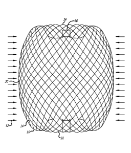
Referring to FIGS. 3-10, an embodiment of a device for treatment of a
patient's
vasculature 10 is shown. The device 10 includes a self-expanding resilient
permeable
shell 40 having a proximal end 32, a distal end 34, a longitudinal axis 46 and
further
comprising a plurality of elongate resilient filaments 14 including large
filaments 48
and small filaments 50 of at least two different transverse dimensions as
shown in
more detail in FIGS 5,7 and 18. The filaments 14 have a woven structure and
are
secured relative to each other at proximal ends 60 and distal ends 62 thereof.
The
permeable shell 40 of the device has a radially constrained elongated state
configured
for delivery within a microcatheter 61, as shown in FIG. 11, with the thin
woven
filaments 14 extending longitudinally from the proximal end 42 to the distal
end 44
radially adjacent each other along a length of the filaments.
As shown in FIGS. 3-6, the permeable shell 40 also has an expanded relaxed
state with a globular and longitudinally shortened configuration relative to
the radially
constrained state. In the expanded state, the woven filaments 14 form the self-
expanding resilient permeable shell 40 in a smooth path radially expanded from
a
longitudinal axis 46 of the device between the proximal end 32 and distal end
34. The
woven structure of the filaments 14 includes a plurality of openings 64 in the
permeable shell 40 formed between the woven filaments. For some embodiments,
the largest of said openings 64 may be configured to allow blood flow through
the
CA 02722672 2010-10-26
WO 2009/135166 PCT/US2009/042592
openings only at a velocity below a thrombotic threshold velocity. Thrombotic
threshold velocity has been defined, at least by some, as the time-average
velocity at
which more than 50% of a vascular graft surface is covered by thrombus when
deployed within a patient's vasculature. In the context of aneurysm occlusion,
a
.. slightly different threshold may be appropriate. Accordingly, the
thrombotic threshold
velocity as used herein shall include the velocity at which clotting occurs
within or on a
device, such as device 10, deployed within a patient's vasculature such that
blood
flow into a vascular defect treated by the device is substantially blocked in
less than
about 1 hour or otherwise during the treatment procedure. The blockage of
blood
flow into the vascular defect may be indicated in some cases by minimal
contrast
agent entering the vascular defect after a sufficient amount of contrast agent
has been
injected into the patient's vasculature upstream of the implant site and
visualized as it
dissipates from that site. Such sustained blockage of flow within less than
about 1
hour or during the duration of the implantation procedure may also be referred
to as
acute occlusion of the vascular defect.
As such, once the device 10 is deployed, any blood flowing through the
permeable shell may be slowed to a velocity below the thrombotic threshold
velocity
and thrombus will begin to form on and around the openings in the permeable
shell
40. Ultimately, this process may be configured to produce acute occlusion of
the
vascular defect within which the device 10 is deployed. For some embodiments,
at
least the distal end of the permeable shell 40 may have a reverse bend in an
everted
configuration such that the secured distal ends 62 of the filaments 14 are
withdrawn
axially within the nominal permeable shell structure or contour in the
expanded state.
For some embodiments, the proximal end of the permeable shell further includes
a
reverse bend in an everted configuration such that the secured proximal ends
60 of
the filaments 14 are withdrawn axially within the nominal permeable shell
structure 40
in the expanded state. As used herein, the term everted may include a
structure that
is everted, partially everted and/or recessed with a reverse bend as shown in
the
device embodiment of FIGS. 3-6. For such embodiments, the ends 60 and 62 of
the
filaments 14 of the permeable shell or hub structure disposed around the ends
may be
withdrawn within or below the globular shaped periphery of the permeable shell
of the
device.
The elongate resilient filaments 14 of the permeable shell 40 may be secured
relative to each other at proximal ends 60 and distal ends 62 thereof by one
or more
21
CA 02722672 2010-10-26
WO 2009/135166 PCT/US2009/042592
methods including welding, soldering, adhesive bonding, epoxy bonding or the
like. In
addition to the ends of the filaments being secured together, a distal hub 66
may also
be secured to the distal ends 62 of the thin filaments 14 of the permeable
shell 40 and
a proximal hub 68 secured to the proximal ends 60 of the thin filaments 14 of
the
permeable shell 40. The proximal hub 68 may include a cylindrical member that
extends proximally beyond the proximal ends 60 of the thin filaments so as to
form a
cavity 70 within a proximal portion of the proximal hub 68. The proximal
cavity 70
may be used for holding adhesives such as epoxy, solder or any other suitable
bonding agent for securing an elongate detachment tether 72 that may in turn
be
detachably secured to a delivery apparatus such as is shown in FIGS. 11-15.
For some embodiments, the elongate resilient filaments 14 of the permeable
shell 40 may have a transverse cross section that is substantially round in
shape and
be made from a superelastic material that may also be a shape memory metal.
The
shape memory metal of the filaments of the permeable shell 40 may be heat set
in the
globular configuration of the relaxed expanded state as shown in FIGS. 3-6.
Suitable
superelastic shape memory metals may include alloys such as NiTi alloy and the
like.
The superelastic properties of such alloys may be useful in providing the
resilient
properties to the elongate filaments 14 so that they can be heat set in the
globular
form shown, fully constrained for delivery within an inner lumen of a
microcatheter and
then released to self expand back to substantially the original heat set shape
of the
globular configuration upon deployment within a patient's body.
The devicel 0 may have an everted filamentary structure with a permeable
shell 40 having a proximal end 32 and a distal end 34 in an expanded relaxed
state.
The permeable shell 40 has a substantially enclosed configuration for the
embodiments shown. Some or all of the permeable shell 40 of the device 10 may
be
configured to substantially block or impede fluid flow or pressure into a
vascular defect
or otherwise isolate the vascular defect over some period of time after the
device is
deployed in an expanded state. The permeable shell 40 and device 10 generally
also
has a low profile, radially constrained state, as shown in FIG. 11, with an
elongated
tubular or cylindrical configuration that includes the proximal end 32, the
distal end 34
and a longitudinal axis 46. While in the radially constrained state, the
elongate flexible
filaments 14 of the permeable shell 40 may be disposed substantially parallel
and in
close lateral proximity to each other between the proximal end and distal end
forming
a substantially tubular or compressed cylindrical configuration.
22
CA 02722672 2010-10-26
WO 2009/135166
PCT/US2009/042592
Proximal ends 60 of at least some of the filaments 14 of the permeable shell
40
may be secured to the proximal hub 68 and distal ends 62 of at least some of
the
filaments 14 of the permeable shell 40 are secured to the distal hub 66, with
the
proximal hub 68 and distal hub 66 being disposed substantially concentric to
the
longitudinal axis 46 as shown in FIG. 4. The ends of the filaments 14 may be
secured
to the respective hubs 66 and 68 by any of the methods discussed above with
respect
to securement of the filament ends to each other, including the use of
adhesives,
solder, welding and the like. A middle portion 30 of the permeable shell 40
may have
a first transverse dimension with a low profile suitable for delivery from a
microcatheter as shown in FIG. 11. Radial constraint on the device 10 may be
applied by an inside surface of the inner lumen of a microcatheter, such as
the distal
end portion of the microcatheter 61 shown, or it may be applied by any other
suitable
mechanism that may be released in a controllable manner upon ejection of the
device
10 from the distal end of the catheter. In FIG. 11 a proximal end or hub 68 of
the
device 10 is secured to a distal end of an elongate delivery apparatus 110 of
a
delivery system 112 disposed at the proximal hub 68 of the device 10.
Some device embodiments 10 having a braided or woven filamentary structure
may be formed using about 10 filaments to about 300 filaments 14, more
specifically,
about 10 filaments to about 100 filaments14, and even more specifically, about
60
filaments to about 80 filaments 14. Some embodiments of a permeable shell 40
may
include about 70 filaments to about 300 filaments extending from the proximal
end 32
to the distal end 34, more specifically, about 100 filaments to about 200
filaments
extending from the proximal end 32 to the distal end 34. For some embodiments,
the
filaments 14 may have a transverse dimension or diameter of about 0.0008
inches to
about 0.004 inches. The elongate resilient filaments 14 in some cases may have
an
outer transverse dimension or diameter of about 0.0005 inch to about 0.005
inch,
more specifically, about 0.001 inch to about 0.003 inch, and in some cases
about
0.0004 inches to about 0.002 inches. For some device embodiments 10 that
include
filaments 14 of different sizes, the large filaments 48 of the permeable shell
40 may
have a transverse dimension or diameter that is about 0.001 inches to about
0.004
inches and the small filaments 50 may have a transverse dimension or diameter
of
about 0.0004 inches to about 0.0015 inches, more specifically, about 0.0004
inches to
about 0.001 inches. In addition, a difference in transverse dimension or
diameter
between the small filaments 50 and the large filaments 48 may be less than
about
23
CA 02722672 2010-10-26
WO 2009/135166 PCT/US2009/042592
0.004 inches, more specifically, less than about 0.0035 inches, and even more
specifically, less than about 0.002 inches. For embodiments of permeable
shells 40
that include filaments 14 of different sizes, the number of small filaments 50
of the
permeable shell 40 relative to the number of large filaments 48 of the
permeable shell
40 may be about 2 to 1 to about 15 to 1, more specifically, about 2 to 1 to
about 12 to
1, and even more specifically, about 4 to 1 to about 8 to 1.
The expanded relaxed state of the permeable shell 40, as shown in FIG. 4, has
an axially shortened configuration relative to the constrained state such that
the
proximal hub 68 is disposed closer to the distal hub 66 than in the
constrained state.
Both hubs 66 and 68 are disposed substantially concentric to the longitudinal
axis 46
of the device and each filamentary element 14 forms a smooth arc between the
proximal and distal hubs 66 and 68 with a reverse bend at each end. A
longitudinal
spacing between the proximal and distal hubs 66 and 68 of the permeable shell
40 in
a deployed relaxed state may be about 25 percent to about 75 percent of the
longitudinal spacing between the proximal and distal hubs 66 and 68 in the
constrained cylindrical state, for some embodiments. The arc of the filaments
14
between the proximal and distal ends 32 and 34 may be configured such that a
middle
portion of each filament 14 has a second transverse dimension substantially
greater
than the first transverse dimension.
For some embodiments, the permeable shell 40 may have a first transverse
dimension in a collapsed radially constrained state of about 0.2 mm to about 2
mm
and a second transverse dimension in a relaxed expanded state of about 4 mm to
about 30 mm. For some embodiments, the second transverse dimension of the
permeable shell 40 in an expanded state may be about 2 times to about 150
times the
first transverse dimension, more specifically, about 10 times to about 25
times the first
or constrained transverse dimension. A longitudinal spacing between the
proximal end
32 and distal end 34 of the permeable shell 40 in the relaxed expanded state
may be
about 25% percent to about 75% percent of the spacing between the proximal end
32
and distal end 34 in the constrained cylindrical state. For some embodiments,
a major
transverse dimension of the permeable shell 40 in a relaxed expanded state may
be
about 4 mm to about 30 mm, more specifically, about 9 mm to about 15 mm, and
even more specifically, about 4 mm to about 8 mm.
An arced portion of the filaments 14 of the permeable shell 40 may have a
sinusoidal-like shape with a first or outer radius 88 and a second or inner
radius 90
24
CA 02722672 2010-10-26
WO 2009/135166 PCT/US2009/042592
near the ends of the permeable shell 40 as shown in FIG. 6. This sinusoid-like
or
multiple curve shape may provide a concavity in the proximal end 32 that may
reduce
an obstruction of flow in a parent vessel adjacent a vascular defect. For some
embodiments, the first radius 88 and second radius 90 of the permeable shell
40 may
be between about 0.12 mm to about 3 mm. For some embodiments, the distance
between the proximal end 32 and distal end 34 may be less than about 60% of
the
overall length of the permeable shell 40 for some embodiments. Such a
configuration
may allow for the distal end 34 to flex downward toward the proximal end 32
when the
device 10 meets resistance at the distal end 34 and thus may provide
longitudinal
conformance. The filaments 14 may be shaped in some embodiments such that
there
are no portions that are without curvature over a distance of more than about
2 mm.
Thus, for some embodiments, each filament 14 may have a substantially
continuous
curvature. This substantially continuous curvature may provide smooth
deployment
and may reduce the risk of vessel perforation. For some embodiments, one of
the
ends 32 or 34 may be retracted or everted to a greater extent than the other
so as to
be more longitudinally or axially conformal than the other end.
The first radius 88 and second radius 90 of the permeable shell 40 may be
between about 0.12 mm to about 3 mm for some embodiments. For some
embodiments, the distance between the proximal end 32 and distal end 34 may be
more than about 60% of the overall length of the expanded permeable shell 40.
Thus,
the largest longitudinal distance between the inner surfaces may be about 60%
to
about 90% of the longitudinal length of the outer surfaces or the overall
length of
device 10. A gap between the hubs 66 and 68 at the proximal end 32 and distal
end
34 may allow for the distal hub 66 to flex downward toward the proximal hub 68
when
the device 10 meets resistance at the distal end and thus provides
longitudinal
conformance. The filaments 14 may be shaped such that there are no portions
that
are without curvature over a distance of more than about 2 mm. Thus, for some
embodiments, each filament 14 may have a substantially continuous curvature.
This
substantially continuous curvature may provide smooth deployment and may
reduce
the risk of vessel perforation. The distal end 34 may be retracted or everted
to a
greater extent than the proximal end 32 such that the distal end portion of
the
permeable shell 40 may be more radially conformal than the proximal end
portion.
Conformability of a distal end portion may provide better device conformance
to
CA 02722672 2010-10-26
WO 2009/135166 PCT/US2009/042592
irregular shaped aneurysms or other vascular defects. A convex surface of the
device
may flex inward forming a concave surface to conform to curvature of a
vascular site.
FIG. 10 shows an enlarged view of the filaments 14 disposed within a proximal
hub 68 of the device 10 with the filaments 14 of two different sizes
constrained and
tightly packed by an outer ring of the proximal hub 68. The tether member 72
may
optionally be disposed within a middle portion of the filaments 14 or within
the cavity
70 of the proximal hub 68 proximal of the proximal ends 60 of the filaments 14
as
shown in FIG. 6. The distal end of the tether 72 may be secured with a knot 92
formed in the distal end thereof which is mechanically captured in the cavity
70 of the
proximal hub 68 formed by a proximal shoulder portion 94 of the proximal hub
68.
The knotted distal end 92 of the tether 72 may also be secured by bonding or
potting
of the distal end of the tether 72 within the cavity 70 and optionally amongst
the
proximal ends 60 of the filaments 14 with mechanical compression, adhesive
bonding,
welding, soldering, brazing or the like. The tether embodiment 72 shown in
FIG. 6
.. has a knotted distal end 92 potted in the cavity of the proximal hub 68
with an
adhesive. Such a tether 72 may be a dissolvable, severable or releasable
tether that
may be part of a delivery apparatus 110 used to deploy the device 10 as shown
in
FIG. 11 and FIGS. 23-26. FIG. 10 also shows the large filaments 48 and small
filaments 50 disposed within and constrained by the proximal hub 68 which may
be
configured to secure the large and small filaments 48 and 50 in place relative
to each
other within the outer ring of the proximal hub 68.
FIGS. 7 and 8 illustrate some configuration embodiments of braided filaments
14 of a permeable shell 40 of the device 10 for treatment of a patient's
vasculature.
The braid structure in each embodiment is shown with a circular shape 100
disposed
within a pore 64 of a woven or braided structure with the circular shape 100
making
contact with each adjacent filament segment. The pore opening size may be
determined at least in part by the size of the filament elements 14 of the
braid, the
angle overlapping filaments make relative to each other and the picks per inch
of the
braid structure. For some embodiments, the cells or openings 64 may have an
elongated substantially diamond shape as shown in FIG. 7, and the pores or
openings
64 of the permeable shell 40 may have a substantially more square shape toward
a
middle portion 30 of the device 10, as shown in FIG. 8. The diamond shaped
pores or
openings 64 may have a length substantially greater than the width
particularly near
the hubs 66 and 68. In some embodiments, the ratio of diamond shaped pore or
26
CA 02722672 2010-10-26
WO 2009/135166 PCT/US2009/042592
opening length to width may exceed a ratio of 3 to 1 for some cells. The
diamond-
shaped openings 64 may have lengths greater than the width thus having an
aspect
ratio, defined as Length/Width of greater than 1. The openings 64 near the
hubs 66
and 68 may have substantially larger aspect ratios than those farther from the
hubs as
shown in FIG. 7. The aspect ratio of openings 64 adjacent the hubs may be
greater
than about 4 to 1. The aspect ratio of openings 64 near the largest diameter
may be
between about 0.75 to 1 and about 2 to 1 for some embodiments. For some
embodiments, the aspect ratio of the openings 64 in the permeable shell 40 may
be
about 0.5 to 1 to about 2 to 1.
The pore size defined by the largest circular shapes 100 that may be disposed
within openings 64 of the braided structure of the permeable shell 40 without
displacing or distorting the filaments 14 surrounding the opening 64 may range
in size
from about 0.005 inches to about 0.01 inches, more specifically, about 0.006
inches to
about 0.009 inches, even more specifically, about 0.007 inches to about 0.008
inches
for some embodiments. In addition, at least some of the openings 64 formed
between
adjacent filaments 14 of the permeable shell 40 of the device 10 may be
configured to
allow blood flow through the openings 64 only at a velocity below a thrombotic
threshold velocity. For some embodiments, the largest openings 64 in the
permeable
shell structure 40 may be configured to allow blood flow through the openings
64 only
at a velocity below a thrombotic threshold velocity. As discussed above, the
pore size
may be less than about 0.016 inches, more specifically, less than about 0.012
inches
for some embodiments. For some embodiments, the openings 64 formed between
adjacent filaments 14 may be about 0.005 inches to about 0.04 inches.
Referring to FIGS. 12-15, a delivery apparatus embodiment 110 of the delivery
system 112 of FIG. 11 is shown in more detail. The apparatus 110 includes an
elongate core wire 114 that extends from a proximal end 116 of the apparatus
110 to
a distal section 118 of the apparatus 110 as shown in FIG. 12. The core wire
114 is
configured to provide sufficient column strength to push a constrained device
10 for
treatment of a patient's vasculature through an inner lumen 120 of the
microcatheter
61 of the delivery system 112 as shown in FIG. 11. The core wire 114 also has
sufficient tensile strength to withdraw or proximally retract the device 10
from a
position outside the microcatheter 61 and axially within the inner lumen 120
of the
microcatheter 61. The tether 72 that extends proximally from the proximal hub
68 is
secured to the distal end of the core wire 114 with a length of shrinkable
tubing 122
27
CA 02722672 2010-10-26
WO 2009/135166
PCT/US2009/042592
that is disposed over a portion of the tether 72 and a distal section of the
core wire
114 and shrunk over both as shown in FIG. 13, although any other suitable
means of
securement may be used.
A heater coil 124 electrically coupled to a first conductor 126 and a second
conductor 128 is disposed over a distal most portion of the tether 72. The
heater coil
124 may also be covered with a length of polymer tubing 130 disposed over the
heater coil 124 distal of the heat shrink tubing 122 that serves to act as a
heat shield
and minimizes the leakage of heat from the heater coil 124 into the
environment, such
as the patient's blood stream, around the delivery apparatus 110. Once the
heat
shrink tubing 122 and insulating polymer tubing 130 have been secured to the
distal
section 118 of the apparatus 110, the proximal portion of the tether 72
disposed
proximal of the heat shrink tubing 122 may be trimmed as shown in FIG. 13. An
over
coil 132 that extends from a distal end 134 of the delivery apparatus 110 to a
proximal
section 136 of the apparatus 110 may then be disposed over the heater coil
124, core
wire 114, tether 72, first conductor 126 and second conductor 128 to hold
these
elements together, produce a low friction outer surface and maintain a desired
flexibility of the delivery apparatus 110. The proximal section 136 of the
apparatus
110 includes the proximal terminus of the over coil 132 which is disposed
distal of a
first contact 138 and second contact 140 which are circumferentially disposed
about
the proximal section 136 of the core wire 114, insulated therefrom, and
electrically
coupled to the first conductor 126 and second conductor 128, respectively as
shown
in FIG. 15.
The heater coil 124 may be configured to receive electric current supplied
through the first conductor 126 and second conductor 128 from an electrical
energy
source 142 coupled to the first contact 138 and second contact 140 at the
proximal
section 136 of the apparatus 110. The electrical current passed through the
heater
coil 124 heats the heater coil to a temperature above the melting point of the
tether
material 72 so as to melt the tether 72 and sever it upon deployment of the
device 10.
Embodiments of the delivery apparatus 110 may generally have a length
greater than the overall length of a microcatheter 61 to be used for the
delivery
system 112. This relationship allows the delivery apparatus 110 to extend,
along with
the device 10 secured to the distal end thereof, from the distal port of the
inner lumen
120 of the microcatheter 61 while having sufficient length extending from a
proximal
end 150 of the microcatheter 61, shown in FIG. 17 discussed below, to enable
28
CA 02722672 2016-01-18
50338-100
manipulation thereof by a physician. For some embodiments, the length of the
delivery apparatus 110 may be about 170 cm to about 200 cm. The core wire 114
may be made from any suitable high strength material such as stainless steel,
NiTi
alloy, or the like. Embodiments of the core wire 114 may have an outer
diameter or
transverse dimension of about 0.010 inch to about 0.015 inch. The over coil
132 may
have an outer diameter or transverse dimension of about 0.018 inch to about
0.03
inch. Although the apparatus embodiment 110 shown in FIGS. 12-15 is activated
by
electrical energy passed through a conductor pair, a similar configuration
that utilizes
light energy passed through a fiber optic or any other suitable arrangement
could be
used to remotely heat a distal heating member or element such as the heater
coil 124
to sever the distal portion of the tether 72. In addition, other delivery
apparatus
embodiments are discussed herein that may also be used for any of
the device embodiments 10 for treatment of a patient's vasculature discussed
herein.
Other delivery and positioning system embodiments may provide for the ability
to rotate a device for treatment of a patient's vasculature in-vivo without
translating
torque along the entire length of the delivery apparatus. Some embodiments for
delivery and positioning of devices 10 are described in co-owned International
PCT
Patent Application No. PCT/US2008/065694 . The delivery and
positioning apparatus may include a distal rotating member that allows
rotational
positioning of the device. The delivery and positioning apparatus may include
a distal
rotating member which rotates an implant in-vivo without the transmission of
torque
along the entire length of the apparatus. Optionally, delivery system may also
rotate
the implant without the transmission of torque in the intermediate portion
between the
proximal end and the distal rotatable end. The delivery and positioning
apparatus may
be releasably secured to any suitable portion of the device for treatment of a
patient's
vasculature.
Device embodiments discussed herein may be releasable from any suitable
flexible, elongate delivery apparatus or actuator such as a guidewire or
guidewire-like
structure. The release of device embodiments from such a delivery apparatus
may be
activated by a thermal mechanism, as discussed above, electrolytic mechanism,
hydraulic mechanism, shape memory material mechanism, or any other mechanism
known in the art of endovascular implant deployment.
Embodiments for deployment and release of therapeutic devices, such as
deployment of embolic devices or stents within the vasculature of a patient,
may
29
CA 02722672 2010-10-26
WO 2009/135166 PCT/US2009/042592
include connecting such a device via a releasable connection to a distal
portion of a
pusher or other delivery apparatus member. The therapeutic device 10 may be
detachably mounted to the distal portion of the apparatus by a filamentary
tether 72,
string, thread, wire, suture, fiber, or the like, which may be referred to
above as the
tether. The tether 72 may be in the form of a monofilament, rod, ribbon,
hollow tube,
or the like. Some embodiments of the tether may have a diameter or maximum
thickness of between about 0.05 mm and 0.2 mm. The tether 72 may be configured
to
be able to withstand a maximum tensile load of between about 0.5 kg and 5 kg.
For
some embodiments, due to the mass of the device 10 being deployed which may be
substantially greater than some embolic devices, some known detachment devices
may lack sufficient tensile strength to be used for some embodiments discussed
herein. As such, it may be desirable to use small very high strength fibers
for some
tether embodiments having a "load at break" greater than about 15 Newtons. For
some embodiments, a tether made from a material known as Dyneema Purity
available from Royal DSM, Heerlen, Netherlands may be used.
The tether 72 may be severed by the input of energy such as electric current
to
a heating element causing release of the therapeutic device. For some
embodiments,
the heating element may be a coil of wire with high electrical resistivity
such as a
platinum-tungsten alloy. The tether member may pass through or be positioned
adjacent the heater element. The heater may be contained substantially within
the
distal portion of the delivery apparatus to provide thermal insulation to
reduce the
potential for thermal damage to the surrounding tissues during detachment. In
another
embodiment, current may pass through the tether which also acts as a heating
element.
Many materials may be used to make tether embodiments 72 including
polymers, metals and composites thereof. One class of materials that may be
useful
for tethers includes polymers such as polyolefin, polyolefin elastomer such as
polyethylene, polyester (PET), polyamide (Nylon), polyurethane, polypropylene,
block
copolymer such as PEBAX or Hytrel, and ethylene vinyl alcohol (EVA); or
rubbery
materials such as silicone, latex, and Kraton. In some cases, the polymer may
also be
cross-linked with radiation to manipulate its tensile strength and melt
temperature.
Another class of materials that may be used for tether embodiment may include
metals such as nickel titanium alloy (Nitinol), gold, platinum, tantalum and
steel.
Other materials that may be useful for tether construction includes wholly
aromatic
CA 02722672 2010-10-26
WO 2009/135166 PCT/US2009/042592
polyester polymers which are liquid crystal polymers (LCP) that may provide
high
performance properties and are highly inert. A commercially available [CF
polymer is
Vectran, which is produced by Kuraray Co. (Tokyo, Japan). The selection of the
material may depend on the melting or softening temperature, the power used
for
detachment, and the body treatment site. The tether may be joined to the
implant
and/or the pusher by crimping, welding, knot tying, soldering, adhesive
bonding, or
other means known in the art.
It should be noted also that many variations of filament and proximal hub
construction such as is detailed above with regard to FIG. 10 may be used for
useful
embodiments of a device for treatment of a patient's vasculature 10. FIG. 16
shows
an enlarged view in transverse cross section of a proximal hub configuration.
For the
embodiment shown, the filaments 14 are disposed within a proximal hub 68 or
end
portion of the device 10 with the filaments 14 constrained and tightly packed
by an
outer ring of the proximal hub 68. A tether member 72 may be disposed within a
middle portion of the filaments 14 or within a cavity of the proximal hub 68
proximal of
the proximal ends 60 of the filaments 14. Such a tether 72 may be a
dissolvable,
severable or releasable tether that may be part of a release apparatus as
discussed
above used to deploy the device.
FIG. 16 illustrates in transverse cross section an embodiment of a proximal
hub
68 showing the configuration of filaments which may be tightly packed and
radially
constrained by an inside surface of the proximal hub 68. In some embodiments,
the
braided or woven structure of the permeable shell 40 formed from such
filaments 14
may be constructed using a large number of small filaments. The number of
filaments14 may be greater than 125 and may also be between about 80 filaments
and about 180 filaments. As discussed above, the total number of filaments 14
for
some embodiments may be about 70 filaments to about 300 filaments, more
specifically, about 100 filaments to about 200 filaments. In some embodiments,
the
braided structure of the permeable shell 40 may be constructed with two or
more
sizes of filaments 14. For example, the structure may have several larger
filaments
that provide structural support and several smaller filaments that provide the
desired
pore size and density and thus flow resistance to achieve a thrombotic
threshold
velocity in some cases. For some embodiments, small filaments 50 of the
permeable
shell 40 may have a transverse dimension or diameter of about 0.0006 inches to
about 0.002 inches for some embodiments and about 0.0004 inches to about 0.001
31
CA 02722672 2010-10-26
WO 2009/135166
PCT/US2009/042592
inches in other embodiments. The large filaments 48 may have a transverse
dimension or diameter of about 0.0015 inches to about 0.004 inches in some
embodiments and about 0.001 inches to about 0.004 inches in other embodiments.
The filaments 14 may be braided in a plain weave that is one under, one over
structure (shown in FIGS. 7 and 8) or a supplementary weave; more than one
warp
interlace with one or more than one weft. The pick count may be varied between
about 25 and 200 picks per inch (PPI).
For some embodiments, the permeable shell 40 or portions thereof may be
porous and may be highly permeable to liquids. In contrast to most vascular
prosthesis fabrics or grafts which typically have a water permeability below
2,000
ml/min/cm2 when measured at a pressure of 120 mmHg, the permeable shell 40 of
some embodiments discussed herein may have a water permeability greater than
about 2,000 ml/min/cm2, in some cases greater than about 2,500 ml/min/cm2. For
some embodiments, water permeability of the permeable shell 40 or portions
thereof
may be between about 2,000 and 10,000 ml/min/cm2, more specifically, about
2,000
ml/min/cm2 to about 15,000 ml/min/cm2, when measured at a pressure of 120
mmHg.
Device embodiments and components thereof may include metals, polymers,
biologic materials and composites thereof. Suitable metals include zirconium-
based
alloys, cobalt-chrome alloys, nickel-titanium alloys, platinum, tantalum,
stainless steel,
titanium, gold, and tungsten. Potentially suitable polymers include but are
not limited
to acrylics, silk, silicones, polyvinyl alcohol, polypropylene, polyvinyl
alcohol,
polyesters (e.g. polyethylene terephthalate or PET), PolyEtherEther Ketone
(PEEK),
polytetrafluoroethylene (PTFE), polycarbonate urethane (PCU) and polyurethane
(PU). Device embodiments may include a material that degrades or is absorbed
or
eroded by the body. A bioresorbable (e.g., breaks down and is absorbed by a
cell,
tissue, or other mechanism within the body) or bioabsorbable (similar to
bioresorbable) material may be used. Alternatively, a bioerodable Je.g.,
erodes or
degrades over time by contact with surrounding tissue fluids, through cellular
activity
or other physiological degradation mechanisms), biodegradable (e.g., degrades
over
time by enzymatic or hydrolytic action, or other mechanism in the body), or
dissolvable material may be employed. Each of these terms is interpreted to be
interchangeable. bioabsorbable polymer. Potentially suitable bioabsorbable
materials
include polylactic acid (PLA), poly(alpha-hydroxy acid) such as poly-L-lactide
(PLLA),
poly-D-lactide (PDLA), polyglycolide (PGA), polydioxanone, polycaprolactone,
32
CA 02722672 2010-10-26
WO 2009/135166 PCT/US2009/042592
polygluconate, polylactic acid-polyethylene oxide copolymers, modified
cellulose,
collagen, poly(hydroxybutyrate), polyanhydride, polyphosphoester, poly(amino
acids),
or related copolymer materials. An absorbable composite fiber may be made by
combining a reinforcement fiber made from a copolymer of about 18% glycolic
acid
and about 82% lactic acid with a matrix material consisting of a blend of the
above
copolymer with about 20% polycaprolactone (PCL).
In any of the suitable device embodiments 10 discussed herein, the permeable
shell structure 40 may include one or more fixation elements or surfaces to
facilitate
fixation of the device within a blood vessel or other vascular site. The
fixation
elements may comprise hooks, barbs, protrusions, pores, microfeatures,
texturing,
bioadhesives or combinations thereof. Embodiments of the support structure may
be
fabricated from a tube of metal where portions are removed. The removal of
material
may be done by laser, electrical discharge machining (EDM), photochemical
etching
and traditional machining techniques. In any of the described embodiments, the
support structure may be constructed with a plurality of wires, cut or etched
from a
sheet of a material, cut or etched from a tube or a combination thereof as in
the art of
vascular stent fabrication.
Permeable shell embodiments 40 may be formed at least in part of wire,
ribbon, or other filamentary elements 14. These filamentary elements 14 may
have
circular, elliptical, ovoid, square, rectangular, or triangular cross-
sections. Permeable
shell embodiments 40 may also be formed using conventional machining, laser
cutting, electrical discharge machining (EDM) or photochemical machining
(PCM). If
made of a metal, it may be formed from either metallic tubes or sheet
material.
Device embodiments 10 discussed herein may be delivered and deployed from
a delivery and positioning system 112 that includes a microcatheter 61, such
as the
type of microcatheter 61 that is known in the art of neurovascular navigation
and
therapy. Device embodiments for treatment of a patient's vasculature 10 may be
elastically collapsed and restrained by a tube or other radial restraint, such
as an inner
lumen 120 of a microcatheter 61, for delivery and deployment. The
microcatheter 61
may generally be inserted through a small incision 152 accessing a peripheral
blood
vessel such as the femoral artery or brachial artery. The microcatheter 61 may
be
delivered or otherwise navigated to a desired treatment site 154 from a
position
outside the patient's body 156 over a guidewire 159 under fluoroscopy or by
other
suitable guiding methods. The guidewire 159 may be removed during such a
33
CA 02722672 2010-10-26
WO 2009/135166 PCT/US2009/042592
procedure to allow insertion of the device 10 secured to a delivery apparatus
110 of
the delivery system 112 through the inner lumen 120 of a microcatheter 61 in
some
cases. FIG. 17 illustrates a schematic view of a patient 158 undergoing
treatment of a
vascular defect 160 as shown in FIG. 18. An access sheath 162 is shown
disposed
.. within either a radial artery 164 or femoral artery 166 of the patient 158
with a delivery
system 112 that includes a microcatheter 61 and delivery apparatus 110
disposed
within the access sheath 162. The delivery system 112 is shown extending
distally
into the vasculature of the patient's brain adjacent a vascular defect 160 in
the
patients brain.
Access to a variety of blood vessels of a patient may be established,
including
arteries such as the femoral artery 166, radial artery 164, and the like in
order to
achieve percutaneous access to a vascular defect 160. In general, the patient
158
may be prepared for surgery and the access artery is exposed via a small
surgical
incision 152 and access to the lumen is gained using the Seldinger technique
where
an introducing needle is used to place a wire over which a dilator or series
of dilators
dilates a vessel allowing an introducer sheath 162 to be inserted into the
vessel. This
would allow the device to be used percutaneously. With an introducer sheath
162 in
place, a guiding catheter 168 is then used to provide a safe passageway from
the
entry site to a region near the target site 154 to be treated. For example, in
treating a
.. site in the human brain, a guiding catheter 168 would be chosen which would
extend
from the entry site 152 at the femoral artery up through the large arteries
extending
around the heart through the aortic arch, and downstream through one of the
arteries
extending from the upper side of the aorta such as the carotid artery 170.
Typically, a
guidewire 159 and neurovascular microcatheter 61 are then placed through the
guiding catheter 168 and advanced through the patients vasculature, until a
distal end
151 of the microcatheter 61 is disposed adjacent or within the target vascular
defect
160, such as an aneurysm. Exemplary guidewires 159 for neurovascular use
include
the Synchro20 made by Boston Scientific and the Glidewire Gold Neuro0 made by
MicroVention Terumo. Typical guidewire sizes may include 0.014 inches and
0.018
.. inches. Once the distal end 151 of the catheter 61 is positioned at the
site, often by
locating its distal end through the use of radiopaque marker material and
fluoroscopy,
the catheter is cleared. For example, if a guidewire 159 has been used to
position the
microcatheter 61, it is withdrawn from the catheter 61 and then the implant
delivery
apparatus 110 is advanced through the microcatheter 61.
34
CA 02722672 2010-10-26
WO 2009/135166 PCT/US2009/042592
Delivery and deployment of device embodiments 10 discussed herein may be
carried out by first compressing the device 10 to a radially constrained and
longitudinally flexible state as shown in FIG. 11. The device 10 may then be
delivered
to a desired treatment site 154 while disposed within the microcatheter 61,
and then
ejected or otherwise deployed from a distal end 151 of the microcatheter 61.
In other
method embodiments, the microcatheter 61 may first be navigated to a desired
treatment site 154 over a guidewire 159 or by other suitable navigation
techniques.
The distal end of the microcatheter 61 may be positioned such that a distal
port of the
microcatheter 61 is directed towards or disposed within a vascular defect 160
to be
.. treated and the guidewire 159 withdrawn. The device 10 secured to a
suitable
delivery apparatus 110 may then be radially constrained, inserted into a
proximal
portion of the inner lumen 120 of the microcatheter 61 and distally advanced
to the
vascular defect 160 through the inner lumen 120.
Once disposed within the vascular defect 160, the device 10 may then allowed
to assume an expanded relaxed or partially relaxed state with the permeable
shell 40
of the device spanning or partially spanning a portion of the vascular defect
160 or the
entire vascular defect 160. The device 10 may also be activated by the
application of
an energy source to assume an expanded deployed configuration once ejected
from
the distal section of the microcatheter 61 for some embodiments. Once the
device 10
is deployed at a desired treatment site 154, the microcatheter 61 may then be
withdrawn.
Some embodiments of devices for the treatment of a patient's vasculature 10
discussed herein may be directed to the treatment of specific types of defects
of a
patient's vasculature. For example, referring to FIG. 18, an aneurysm 160
commonly
.. referred to as a terminal aneurysm is shown in section. Terminal aneurysms
occur
typically at bifurcations in a patient's vasculature where blood flow,
indicated by the
arrows 172, from a supply vessel splits into two or more branch vessels
directed away
from each other. The main flow of blood from the supply vessel 174, such as a
basilar
artery, sometimes impinges on the vessel where the vessel diverges and where
the
.. aneurysm sack forms. Terminal aneurysms may have a well defined neck
structure
where the profile of the aneurysm 1 60 narrows adjacent the nominal vessel
profile,
but other terminal aneurysm embodiments may have a less defined neck structure
or
no neck structure. FIG. 19 illustrates a typical berry type aneurysm 160 in
section
where a portion of a wall of a nominal vessel section weakens and expands into
a
CA 02722672 2010-10-26
WO 2009/135166 PCT/US2009/042592
sack like structure ballooning away from the nominal vessel surface and
profile.
Some berry type aneurysms may have a well defined neck structure as shown in
FIG.
19, but others may have a less defined neck structure or none at all. FIG. 19
also
shows some optional procedures wherein a stent 173 or other type of support
has
been deployed in the parent vessel 174 adjacent the aneurysm. Also, shown is
embolic material 176 being deposited into the aneurysm 160 through a
microcatheter
61. Either or both of the stent 173 and embolic material 176 may be so
deployed
either before or after the deployment of a device for treatment of a patient's
vasculature 10.
Prior to delivery and deployment of a device for treatment of a patient's
vasculature 10, it may be desirable for the treating physician to choose an
appropriately sized device 10 to optimize the treatment results. Some
embodiments of
treatment may include estimating a volume of a vascular site or defect 160 to
be
treated and selecting a device 10 with a volume that is substantially the same
volume
.. or slightly over-sized relative to the volume of the vascular site or
defect 160. The
volume of the vascular defect 160 to be occluded may be determined using three-
dimensional angiography or other similar imaging techniques along with
software
which calculates the volume of a selected region. The amount of over-sizing
may be
between about 2% and 15% of the measured volume. In some embodiments, such
as a very irregular shaped aneurysm, it may be desirable to under-size the
volume of
the device 10. Small lobes or "daughter aneurysms" may be excluded from the
volume, defining a truncated volume which may be only partially filled by the
device
without affecting the outcome. A device 10 deployed within such an irregularly
shaped aneurysm 160 is shown in FIG. 28 discussed below. Such a method
embodiment may also include implanting or deploying the device 10 so that the
vascular defect 160 is substantially filled volumetrically by a combination of
device
and blood contained therein. The device 10 may be configured to be
sufficiently
conformal to adapt to irregular shaped vascular defects 160 so that at least
about
75%, in some cases about 80%, of the vascular defect volume is occluded by a
combination of device 10 and blood contained therein.
In particular, for some treatment embodiments, it may be desirable to choose
a device 10 that is properly oversized in a transverse dimension so as to
achieve a
desired conformance, radial force and fit after deployment of the device 10.
FIGS. 20-
22 illustrate a schematic representation of how a device 10 may be chosen for
a
36
CA 02722672 2010-10-26
WO 2009/135166
PCT/US2009/042592
proper fit after deployment that is initially oversized in a transverse
dimension by at
least about 10% of the largest transverse dimension of the vascular defect 160
and
sometimes up to about 100% of the largest transverse dimension. For some
embodiments, the device 10 may be oversized a small amount (e.g. less than
about
1.5 mm) in relation to measured dimensions for the width, height or neck
diameter of
the vascular defect 160.
In FIG. 20, a vascular defect 160 in the form of a cerebral aneurysm is shown
with horizontal arrows 180 and vertical arrows 182 indicating the approximate
largest
interior dimensions of the defect 160. Arrow 180 extending horizontally
indicates the
largest transverse dimension of the defect 160. In FIG. 21, a dashed outline
184 of a
device for treatment of the vascular defect 10 is shown superimposed over the
vascular defect 160 of FIG. 20 illustrating how a device 10 that has been
chosen to be
approximately 20% oversized in a transverse dimension would look in its
unconstrained, relaxed state. FIG 22 illustrates how the device 10 which is
indicated
by the dashed line 184 of FIG. 21 might conform to the interior surface of the
vascular
defect 160 after deployment whereby the nominal transverse dimension of the
device
10 in a relaxed unconstrained state has now been slightly constrained by the
inward
radial force 185 exerted by the vascular defect 160 on the device 10. In
response, as
the filaments 14 of the device 10 and thus the permeable shell 40 made
therefrom
have a constant length, the device 10 has assumed a slightly elongated shape
in the
axial or longitudinal axis of the device 10 so as to elongate and better fill
the interior
volume of the defect 160 as indicated by the downward arrow 186 in FIG. 22.
Once a properly sized device 10 has been selected, the delivery and deployment
process may then proceed. It should also be noted also that the properties of
the
device embodiments 10 and delivery system embodiments 112 discussed herein
generally allow for retraction of a device 10 after initial deployment into a
defect 160,
but before detachment of the device 10. Therefore, it may also be possible and
desirable to withdraw or retrieve an initially deployed device 10 after the
fit within the
defect 160 has been evaluated in favor of a differently sized device 10. An
example
of a terminal aneurysm 160 is shown in FIG. 23 in section. The tip 151 of a
catheter,
such as a microcatheter 61 may be advanced into or adjacent the vascular site
or
defect 160 (e.g. aneurysm) as shown in FIG. 24. For some embodiments, an
embolic
coil or other vaso-occlusive device or material 176 (as shown for example in
FIG. 19)
may optionally be placed within the aneurysm 160 to provide a framework for
37
CA 02722672 2010-10-26
WO 2009/135166 PCT/US2009/042592
receiving the device 10. In addition, a stent 173 may be placed within a
parent vessel
174 of some aneurysms substantially crossing the aneurysm neck prior to or
during
delivery of devices for treatment of a patient's vasculature discussed herein
(also as
shown for example in FIG. 19). An example of a suitable microcatheter 61
having an
inner lumen diameter of about 0.020 inches to about 0.022 inches is the Rapid
Transit manufactured by Cordis Corporation. Examples of some suitable
microcatheters 61 may include microcatheters having an inner lumen diameter of
about 0.026 inch to about 0.028 inch, such as the Rebar by Ev3 Company, the
Renegade Hi-Flow by Boston Scientific Corporation, and the Mass Transit by
Cord is Corporation. Suitable microcatheters having an inner lumen diameter of
about
0.031 inch to about 0.033 inch may include the Marksmen by Chestnut Medical
Technologies, Inc. and the Vasco 28 by Bait Extrusion. A suitable
microcatheter 61
having an inner lumen diameter of about 0.039 inch to about 0.041 inch
includes the
Vasco 35 by Bait Extrusion. These microcatheters 61 are listed as exemplary
embodiments only, other suitable microcatheters may also be used with any of
the
embodiments discussed herein.
Detachment of the device 10 from the delivery apparatus 110 may be
controlled by a control switch 188 disposed at a proximal end of the delivery
system
112, which may also be coupled to an energy source 142, which severs the
tether 72
that secures the proximal hub 68 of the device 10 to the delivery apparatus
110.
While disposed within the microcatheter 61 or other suitable delivery system
112, as
shown in FIG. 11, the filaments 14 of the permeable shell 40 may take on an
elongated, non-everted configuration substantially parallel to each other and
a
longitudinal axis of the catheter 61. Once the device 10 is pushed out of the
distal
port of the microcatheter 61, or the radial constraint is otherwise removed,
the distal
ends 62 of the filaments 14 may then axially contract towards each other so as
to
assume the globular everted configuration within the vascular defect 160 as
shown in
FIG. 25.
The device 10 may be inserted through the microcatheter 61 such that the
catheter
lumen 120 restrains radial expansion of the device 10 during delivery. Once
the distal
tip or deployment port of the delivery system 112 is positioned in a desirable
location
adjacent or within a vascular defect 160, the device 10 may be deployed out
the distal
end of the catheter 61 thus allowing the device to begin to radially expand as
shown in
FIG. 25. As the device 10 emerges from the distal end of the delivery system
112, the
38
CA 02722672 2010-10-26
WO 2009/135166 PCT/US2009/042592
device 10 expands to an expanded state within the vascular defect 160, but may
be at
least partially constrained by an interior surface of the vascular defect 160.
Upon full deployment, radial expansion of the device 10 may serve to secure
the
device 10 within the vascular defect 160 and also deploy the permeable shell
40
across at least a portion of an opening 190 (e.g. aneurysm neck) so as to at
least
partially isolate the vascular defect 160 from flow, pressure or both of the
patient's
vasculature adjacent the vascular defect 160 as shown in FIG. 26. The
conformability
of the device 10, particularly in the neck region 190 may provide for improved
sealing.
For some embodiments, once deployed, the permeable shell 40 may substantially
slow flow of fluids and impede flow into the vascular site and thus reduce
pressure
within the vascular defect 160. For some embodiments, the device 10 may be
implanted substantially within the vascular defect 160, however, in some
embodiments, a portion of the device 10 may extend into the defect opening or
neck
190 or into branch vessels.
One exemplary case study that has been conducted includes a procedure
performed on a female canine where an aneurysm was surgically created in the
subject canine. The target aneurysm prior to treatment had a maximum
transverse
dimension of about 8 mm, a length of about 10 mm and a neck measurement of
about
5.6 mm. The device 10 deployed included a permeable shell 40 formed of 144
resilient filaments having a transverse diameter of about 0.0015 inches
braided into a
globular structure having a transverse dimension of about 10 mm and a
longitudinal
length of about 7 mm in a relaxed expanded state. The maximum size 100 of the
pores 64 of the expanded deployed permeable shell 40 was about 0.013 inches.
The
device was delivered to the target aneurysm using a 5 Fr. Guider Softip XF
guide
catheter made by Boston Scientific. The maximum size 100 of the pores 64 of
the
portion of the expanded deployed permeable shell 40 that spanned the neck of
the
aneurysm again was about 0.013 inches. Five minutes after detachment from the
delivery system, the device 10 had produced acute occlusion of the aneurysm.
Another exemplary case study conducted involved treatment of a surgically
created aneurysm in a New Zealand White Rabbit. The target aneurysm prior to
treatment had a maximum transverse dimension of about 3.6 mm, length of about
5.8
mm and a neck measurement of about 3.4 mm. The device 10 deployed included a
permeable shell formed of 144 resilient filaments having a transverse diameter
of
about 0.001 inches braided into a globular structure having a transverse
dimension of
39
CA 02722672 2010-10-26
WO 2009/135166 PCT/US2009/042592
about 4 mm and a length of about 5 mm in a relaxed expanded state. The pore
size
100 of the portion of the braided mesh of the expanded deployed permeable
shell 40
that was configured to span the neck of the vascular defect was about 0.005
inches.
The device was delivered to the surgically created aneurysm with a 5 Fr. Envoy
SIR
guide catheter manufactured by Cordis Neurovascular. A Renegade Hi-Flo
microcatheter manufactured by Boston Scientific having an inner lumen diameter
of
about 0.027 inches was then inserted through the guide catheter and served as
a
conduit for delivery of the device 10 secured to a distal end of a delivery
apparatus.
Once the device 10 was deployed within the vascular defect 160, the vascular
defect
160 achieved at least partial occlusion at 5 minutes from implantation.
However, due
to the sensitivity of the subject animal to angiographic injection and
measurement, no
further data was taken during the procedure. Complete occlusion was observed
for
the device when examined at 3 weeks from the procedure.
For some embodiments, as discussed above, the device 10 may be manipulated
by the user to position the device 10 within the vascular site or defect 160
during or
after deployment but prior to detachment. For some embodiments, the device 10
may
be rotated in order to achieve a desired position of the device 10 and, more
specifically, a desired position of the permeable shell 40, prior to or during
deployment
of the device 10. For some embodiments, the device 10 may be rotated about a
longitudinal axis of the delivery system 112 with or without the transmission
or
manifestation of torque being exhibited along a middle portion of a delivery
catheter
being used for the delivery. It may be desirable in some circumstances to
determine
whether acute occlusion of the vascular defect 160 has occurred prior to
detachment
of the device 10 from the delivery apparatus 110 of the delivery system 112.
These
delivery and deployment methods may be used for deployment within berry
aneurysms, terminal aneurysms, or any other suitable vascular defect
embodiments
160. Some method embodiments include deploying the device 10 at a confluence
of
three vessels of the patient's vasculature that form a bifurcation such that
the
permeable shell 40 of the device 10 substantially covers the neck of a
terminal
aneurysm. Once the physician is satisfied with the deployment, size and
position of
the device 10, the device 10 may then be detached by actuation of the control
switch
188 by the methods described above and shown in FIG. 26. Thereafter, the
device 10
is in an implanted state within the vascular defect 160 to effect treatment
thereof.
CA 02722672 2010-10-26
WO 2009/135166
PCT/US2009/042592
FIG. 27 illustrates another configuration of a deployed and implanted device
in a
patients vascular defect 160. While the implantation configuration shown in
FIG. 26
indicates a configuration whereby the longitudinal axis 46 of the device 10 is
substantially aligned with a longitudinal axis of the defect 160, other
suitable and
clinically effective implantation embodiments may be used. For example, FIG.
27
shows an implantation embodiment whereby the longitudinal axis 46 of the
implanted
device 10 is canted at an angle of about 10 degrees to about 90 degrees
relative to a
longitudinal axis of the target vascular defect 160. Such an alternative
implantation
configuration may also be useful in achieving a desired clinical outcome with
acute
occlusion of the vascular defect 160 in some cases and restoration of normal
blood
flow adjacent the treated vascular defect. FIG. 28 illustrates a device 10
implanted in
an irregularly shaped vascular defect 160. The aneurysm 160 shown has at least
two
distinct lobes 192 extending from the main aneurysm cavity. The two lobes 192
shown are unfilled by the deployed vascular device 10, yet the lobes 192 are
still
isolated from the parent vessel of the patient's body due to the occlusion of
the
aneurysm neck portion 190.
Markers, such as radiopaque markers, on the device 10 or delivery system 112
may be used in conjunction with external imaging equipment (e.g. x-ray) to
facilitate
positioning of the device or delivery system during deployment. Once the
device is
properly positioned, the device 10 may be detached by the user. For some
embodiments, the detachment of the device 10 from the delivery apparatus 110
of the
delivery system 112 may be affected by the delivery of energy (e.g. heat,
radiofrequency, ultrasound, vibrational, or laser) to a junction or release
mechanism
between the device 10 and the delivery apparatus 110. Once the device 10 has
been
detached, the delivery system 112 may be withdrawn from the patient's
vasculature or
patient's body 158. For some embodiments, a stent 173 may be place within the
parent vessel substantially crossing the aneurysm neck 190 after delivery of
the
device 10 as shown in FIG. 19 for illustration.
For some embodiments, a biologically active agent or a passive therapeutic
agent
may be released from a responsive material component of the device 10. The
agent
release may be affected by one or more of the body's environmental parameters
or
energy may be delivered (from an internal or external source) to the device
10.
Hemostasis may occur within the vascular defect 160 as a result of the
isolation of the
vascular defect 160, ultimately leading to clotting and substantial occlusion
of the
41
CA 02722672 2010-10-26
WO 2009/135166 PCT/US2009/042592
vascular defect 160 by a combination of thrombotic material and the device 10.
For
some embodiments, thrombosis within the vascular defect 160 may be facilitated
by
agents released from the device 10 and/or drugs or other therapeutic agents
delivered
to the patient.
For some embodiments, once the device 10 has been deployed, the
attachment of platelets to the permeable shell 40 may be inhibited and the
formation
of clot within an interior space of the vascular defect 160, device, or both
promoted or
otherwise facilitated with a suitable choice of thrombogenic coatings, anti-
thrombogenic coatings or any other suitable coatings (not shown) which may be
disposed on any portion of the device 10 for some embodiments, including an
outer
surface of the filaments 14 or the hubs 66 and 68. Such a coating or coatings
may be
applied to any suitable portion of the permeable shell 40. Energy forms may
also be
applied through the delivery apparatus 110 and/or a separate catheter to
facilitate
fixation and/or healing of the device 10 adjacent the vascular defect 160 for
some
embodiments. One or more embolic devices or embolic material 176 may also
optionally be delivered into the vascular defect 160 adjacent permeable shell
portion
that spans the neck or opening 190 of the vascular defect 160 after the device
10 has
been deployed. For some embodiments, a stent or stent-like support device 173
may
be implanted or deployed in a parent vessel adjacent the defect 160 such that
it spans
across the vascular defect 160 prior to or after deployment of the vascular
defect
treatment device 10.
In any of the above embodiments, the device 10 may have sufficient radial
compliance so as to be readily retrievable or retractable into a typical
microcatheter
61. The proximal portion of the device 10, or the device as a whole for some
embodiments, may be engineered or modified by the use of reduced diameter
filaments, tapered filaments, or filaments oriented for radial flexure so that
the device
10 is retractable into a tube that has an internal diameter that is less than
about 0.7
mm, using a retraction force less than about 2.7 Newtons (0.6 lbf) force. The
force for
retrieving the device 10 into a microcatheter 61 may be between about 0.8
Newtons
(0.18 lbf) and about 2.25 Newtons (0.5 lbf).
Engagement of the permeable shell 40 with tissue of an inner surface of a
vascular defect 160, when in an expanded relaxed state, may be achieved by the
exertion of an outward radial force against tissue of the inside surface of
the cavity of
the patient's vascular defect 160 as shown in FIG. 29. A similar outward
radial force
42
CA 02722672 2010-10-26
WO 2009/135166 PCT/US2009/042592
may also be applied by a proximal end portion and permeable shell 40 of the
device
so as to engage the permeable shell 40 with an inside surface or adjacent
tissue of
the vascular defect 160. Such forces may be exerted in some embodiments
wherein
the nominal outer transverse dimension or diameter of the permeable shell 40
in the
5 relaxed unconstrained state is larger than the nominal inner transverse
dimension of
the vascular defect 160 within which the device 10 is being deployed, i.e.,
oversizing
as discussed above. The elastic resiliency of the permeable shell 40 and
filaments 14
thereof may be achieved by an appropriate selection of materials, such as
superelastic alloys, including nickel titanium alloys, or any other suitable
material for
10 some embodiments. The conformability of a proximal portion of the
permeable shell
40 of the device 10 may be such that it will readily ovalize to adapt to the
shape and
size of an aneurysm neck 190, as shown in FIGS. 20-22, thus providing a good
seal
and barrier to flow around the device. Thus the device 10 may achieve a good
seal,
substantially preventing flow around the device without the need for fixation
members
that protrude into the parent vessel.
Some implanted device embodiments 10 have the ends of the filaments 14 of
the permeable shell 40 disposed even with or just within a plane formed by the
apices
of the filaments disposed adjacent to the ends. Some embodiments of the device
10
may also include a sealing member disposed within or about a perimeter zone
198 or
other suitable portion of the permeable shell 40 and be configured to
facilitate the
disruption of flow, a fibrotic tissue response, or physically form a seal
between the
permeable shell 40 and a surface of the patient's vasculature. The sealing
member
may comprise coatings, fibers or surface treatments as described herein. The
sealing
member may be in a part or all of an area of the periphery of the device
adjacent
where the device contacts the wall of the aneurysm near the aneurysm neck
(sealing
zone 198) as shown in FIGS. 29 and 30. The zone may extend from about the apex
of
the outer proximal end radius 88 for a distance up to about 20% of the height
of the
expanded device 10. The sealing zone 198 may include between about 5% and 30%
of the device 10 surface area. Since the flow of blood into an aneurysm 160
generally favors one side of the opening, the sealing member may be
incorporated in
or attached to the permeable shell 40 structure throughout the peripheral area
(sealing zone 198) shown in Figure 30. Some embodiments of the sealing member
may include a swellable polymer. In some embodiments, the sealing member may
43
CA 02722672 2016-01-18
50338-100
include or bioactive material or agent such as a biologic material or
biodegradable,
bieresorbable or other bioactive polymer or copolymers thereof.
Any embodiment of devices for treatment of a patient's vasculature 10,
delivery
system 112 for such devices 10 or both discussed herein may be adapted to
deliver
energy to the device for treatment of a patient's vasculature or to tissue
surrounding
the device 10 at the implant site for the purpose of facilitating fixation of
a device 10,
healing of tissue adjacent the device or both. In some embodiments, energy may
be
delivered through a delivery system 112 to the device 10 for treatment of a
patient's
vasculature such that the device 10 is heated. In some embodiments, energy may
be
delivered via a separate elongate instrument (e.g. catheter, not shown) to the
device
10 for treatment of a patient's vasculature and/or surrounding tissue at the
site of the
implant 154. Examples of energy embodiments that may be delivered include but
are
not limited to light energy, thermal or vibration energy, electromagnetic
energy, radio
frequency energy and ultrasonic energy. For some embodiments, energy delivered
to
.. the device 10 may trigger the release of chemical or biologic agents to
promote
fixation of a device for treatment of a patient's vasculature 10 to a
patient's tissue,
healing of tissue disposed adjacent such a device 10 or both.
The permeable shell 40 of some device embodiments 10 may also be
configured to react to the delivery of energy to effect a change in the
mechanical or
.. structural characteristics, deliver drugs or other bioactive agents or
transfer heat to the
surrounding tissue. For example, some device embodiments 10 may be made softer
or more rigid from the use of materials that change properties when exposed to
electromagnetic energy (e.g. heat, light, or radio frequency energy). In some
cases,
the permeable shell 40 may include a polymer that reacts in response to
physiologic
fluids by expanding. An exemplary material is described by Cox in U.S. Patent
Application No. 2004/0186562, filed January 22, 2004, titled "Aneurysm
Treatment
Device and Method of Use".
Device embodiments 10 and components thereof discussed herein may take
on a largo variety of configurations to achieve specific or generally
desirable clinical
results. In some device embodiments 10, the start of the braided structure of
the
permeable shell 40 may be delayed from the proximal hub 68 so that the
filaments 1
emanate from the proximal hub 68 in a spoke-like radial fashion as shown in
the
proximal end view of a device in FIG. 31. A flattened analog version of the
braid
pattern of FIG. 31 is also shown in FIG. 33. This configuration may result in
a smaller
44
CA 02722672 2016-01-18
width gap between the filaments 14 at a given radial distance from the
proximal hub
68 relative to a fully braided configuration, the flattened analog pattern of
which is
shown in FIG. 34. This may provide better flow disruption and promote
hemostasis in
the area of the device 10 that may be subjected to the highest flow rates.
FIG. 32
illustrates a flattened analog representation of a non-braided filament
structure for
reference.
The woven structure may include a portion where the weave or braid of the
filaments 14 is interrupted as shown in a flat pattern analog pattern in FIG.
35. In the
interrupted region, the filaments 14 may be substantially parallel to each
other. The
interrupted area may provide a region with different mechanical
characteristics such
as radial stiffness and/or compliance. Further, the interrupted region may
allow for the
addition of non-structural fibers or sealing members 200 as described herein
or other
elements to facilitate fixation, healing, fibrosis or thrombosis. The
interrupted region
may be within, part of or adjacent to the sealing member zone 198 as shown in
FIGS.
29 and 30. The interrupted region may be less than about 50% of the surface
area
and may be between about 5% and 25% of the surface area.
In some embodiments, filamentary or fibrous members that are substantially
non-structural may be attached or interwoven into the structural filaments of
a portion
of the permeable shell to increase a resistance to the flow of blood through
the
permeable shell structure 40. In some embodiments, a plurality of fibers 200
may be
attached on the inner surface of the permeable shell 40 near the proximal hub
68 as
shown in FIG. 36. The fibrous members 200 may be the fibers that form the
detachment system tether for some embodiments. In some embodiments, one or
more fibers 200 may be interwoven into the permeable shell filaments 14 as
shown in
.. Figure 37. The non-structural fibers 200, which may be microfibers or any
other
suitable fibers, may be polymeric. The non-structural fibers 200 may include,
but not
limited to, any of the fibers or microfibers discussed herein.
In some cases, device embodiments for treatment of a patient's vasculature 10
may generally be fabricated by braiding a substantially tubular braided
structure with
filamentary elements 14, forming the braided tubular structure into a desired
shape,
and heat setting the braided formed filaments into the desired shape. Once so
formed, the ends of the elongate resilient filaments 14 may then be secured
together
relative to each other by any of the methods discussed above and proximal and
distal
hubs 66 and 68 added.
CA 02722672 2010-10-26
WO 2009/135166 PCT/US2009/042592
Such a braiding process may be carried out by automated machine fabrication
or may also be performed by hand. An embodiment of a process for braiding a
tubular braided structure by a manual process is shown in FIG. 38. A plurality
of
elongate resilient filaments 14 are secured at one end of an elongate
cylindrical
braiding mandrel 202 by a constraining band 204. The band 204 may include any
suitable structure that secured the ends of the filaments 14 relative to the
mandrel 202
such as a band of adhesive tape, an elastic band, an annular clamp or the
like. The
loose ends of the filaments 14 opposite the secured ends are being manipulated
in a
braided or woven pattern as indicated by the arrows 206 to achieve a one over-
one
under braid pattern for generation of a braided tubular member 208. As
discussed
above, although a one over-one under simple braid pattern is shown and
discussed,
other braid or weave patterns may also be used. One such example of another
braid
configuration may include a two over-one under pattern. FIG. 39 illustrates
the
braided tubular member 208 taking shape and lengthening as the braiding
process
continues as indicated by the arrows 206 in FIG. 39. Once the braided tubular
member 208 achieves sufficient length, it may be removed from the braiding
mandrel
202 and positioned within a shaping fixture such as the shaping fixture
embodiments
shown in FIGS. 40 and 41.
FIG. 40 shows the tubular braided member 208 disposed over an internal rod
mandrel 210 that extends through central lumens of an internal ball mandrel
212 and
a pair of opposed recessed end forming mandrels 214. The tubular braided
member
208 is also disposed over an outer surface of the internal ball mandrel 212
and within
an inner lumen of each of the end forming mandrels 214. In order to hold the
braided
tubular member 208 onto an outer surface contour of the internal ball mandrel
212,
including the recessed ends 216 thereof, the end forming mandrels 214 are
configured to be pushed against and into the recessed ends 216 of the internal
ball
mandrel 212 such that the inside surface of the braided tubular member 208 is
held
against the outer contour of the internal ball mandrel 212 and fixed in place.
This
entire fixture 220 with the inside surface of the braided tubular structure
208 held
against the outside surface of the internal ball mandrel 212 may then be
subjected to
an appropriate heat treatment such that the resilient filaments 14 of the
braided
tubular member 208 assume or are otherwise shape-set to the outer contour of
the
central ball mandrel 212. In some embodiments, the filamentary elements 14 of
the
permeable shell 40 may be held by a fixture configured to hold the permeable
shell 40
46
CA 02722672 2010-10-26
WO 2009/135166 PCT/US2009/042592
in a desired shape and heated to about 475-525 degrees C for about 5-10
minutes to
shape-set the structure.
The central ball mandrel 212 may be configured to have any desired shape so
as to produce a shape set tubular braided member 208 that forms a permeable
shell
40 having a desired shape and size such as the globular configuration of the
device
of FIGS. 3-6 above, or any other suitable configuration. As such, the central
ball
mandrel 212 may also be a globular-shaped ball with recesses in opposing sides
for
the hubs 66 and 68 that is placed inside the tubular braid 208. A mold or
molds that
have one or more pieces that are assembled to form a cavity with the desired
device
10 shape may also be used in conjunction with or in place of the end
forming mandrels
214. Once the heat set process in complete, fibers, coatings, surface
treatments may
be added to certain filaments, portions of filaments, or all of the permeable
shell 40
structure that results. Further, for some embodiments of device processing,
the
permeable shell 40 may be formed as discussed above by securing proximal ends
60
and distal ends 62 of elongate filamentary elements 14, or to respective
proximal and
distal hubs 66 and 68.
FIG. 41 shows another embodiment of a fixture for shape setting the
permeable shell 40 of a device for treatment of a patient's vasculature. The
fixture
embodiment 230 of FIG. 41 may be used in essentially the same manner as the
fixture embodiment 220 of FIG. 40, except that instead of a central ball
mandrel 212,
an internal tube mandrel 232 is used in conjunction with an external tube
restraint 234
in order to hold the shape of the braided tubular member 208 during the heat
setting
process. More specifically, the tubular braided member 208 is disposed over an
internal rod mandrel 210 that extends through central lumens of the internal
tube
mandrel 232 and a pair of opposed recessed end forming mandrels 214. The
tubular
braided member 208 is also disposed over an outer surface of the internal tube
mandrel 232 and within an inner lumen of each of the end forming mandrels 214.
In order to hold the braided tubular member 208 into a desired shape,
including
the recessed ends thereof, the end forming mandrels 214 are configured to be
pushed
against and into recessed ends 238 of the internal tube mandrel 232 such that
the
inside surface of the braided tubular member 208 is held against the outer
contour of
the internal tube mandrel 232 and fixed in place at the ends of the tube
mandrel 232.
Between the ends of the tube mandrel 232, the braided tubular member 208
radially
expands outwardly until it touches and is radially constrained by an inside
surface of
47
CA 02722672 2010-10-26
WO 2009/135166
PCT/US2009/042592
an external tube mandrel 234. The combination of axial restraint and
securement of
the braided tubular member 208 at the ends of the internal tube mandrel 232 in
conjunction with the inward radial restraint on an outside surface of the
braided
tubular member 208 disposed between the proximal and distal ends thereof, may
be
configured to produce a desired globular configuration suitable for the
permeable shell
40 of the device 10.
Once again, this entire fixture 230 with the inside surface of the ends of the
braided tubular structure 208 held against the outside surface of the ends of
the
internal tube mandrel 232 and an outside surface of the braided tubular member
208
radially constrained by an inside surface 233 of the external tube member 234,
may
then be subjected to an appropriate heat treatment. The heat treatment may be
configured such that the resilient filaments 14 of the braided tubular member
208
assume or are otherwise shape-set to the globular contour of the filaments 14
generated by the fixture 230. In some embodiments, the filamentary elements 14
of
the permeable shell 40 may be held by a fixture configured to hold the braided
tubular
member 208 in a desired shape and heated to about 475-525 degrees C for about
5-
10 minutes to shape-set the structure. The internal tube mandrel 232 and
inside
surface 233 of the external tube member 234 may be so configured to have any
desired shape so as to produce a shape set tubular braided member 208 that
forms a
permeable shell 40 having a desired shape and size such as the globular
configuration of the device of FIGS. 3-6 above, or any other suitable
configuration.
For some embodiments, material may be attached to filaments 14 of the
permeable shell 40 of a device 10 such that it substantially reduces the size
of the
fenestrations, cells or pores 64 between filaments 14 and thus reduces the
porosity in
that area. For example, coating embodiments may be disposed on portions of the
filaments 14 to create small fenestrations or cells and thus higher density of
the
permeable shell 40. Active materials such as a responsive hydrogel may be
attached
or otherwise incorporated into permeable shell 40 of some embodiments such
that it
swells upon contact with liquids over time to reduce the porosity of the
permeable
shell 40.
Device embodiments 10 discussed herein may be coated with various
polymers to enhance it performance, fixation and/or biocompatibility. In
addition,
device embodiments 10 may be made of various biomaterials known in the art of
implant devices including but not limited to polymers, metals, biological
materials and
48
CA 02722672 2010-10-26
WO 2009/135166 PCT/US2009/042592
composites thereof. Device embodiments discussed herein may include cells
and/or
other biologic material to promote healing. Device embodiments discussed
herein
may also be constructed to provide the elution or delivery of one or more
beneficial
drugs, other bioactive substances or both into the blood or the surrounding
tissue.
Permeable shell embodiments 40 of devices for treatment of a patients
vasculature 10 may include multiple layers. A first or outer layer may be
constructed
from a material with low bioactivity and hemocompatibility so as to minimize
platelet
aggregation or attachment and thus the propensity to form clot and thrombus.
Optionally, an outer layer may be coated or incorporate an antithrombogenic
agent
such as heparin or other antithrombogenic agents described herein or known in
the
art. One or more inner layers disposed towards the vascular defect in a
deployed
state relative to the first layer may be constructed of materials that have
greater
bioactivity and/or promote clotting and thus enhance the formation of an
occlusive
mass of clot and device within the vascular defect. Some materials that have
been
shown to have bioactivity and/or promote clotting include silk, polylactic
acid (PLA),
polyglycolic acid (PGA), collagen, alginate, fibrin, fibrinogen, fibronectin,
Methylcellulose, gelatin, Small Intestinal Submucosa (SIS), poly-N-
acetylglucosamine
and copolymers or composites thereof.
Bioactive agents suitable for use in the embodiments discussed herein may
include those having a specific action within the body as well as those having
nonspecific actions. Specific action agents are typically proteinaceous,
including
thrombogenic types and/or forms of collagen, thrombin and fibrogen (each of
which
may provide an optimal combination of activity and cost), as well as elastin
and von
Willebrand factor (which may tend to be less active and/or expensive agents),
and
active portions and domains of each of these agents. Thrombogenic proteins
typically
act by means of a specific interaction with either platelets or enzymes that
participate
in a cascade of events leading eventually to clot formation. Agents having
nonspecific
thrombogenic action are generally positively charged molecules, e.g.,
polymeric
molecules such as chitosan, polylysine, poly(ethylenimine) or acrylics
polymerized
from acrylimide or methacrylamide which incorporate positively-charged groups
in the
form of primary, secondary, or tertiary amines or quartemary salts, or non-
polymeric
agents such as (tridodecylmethylammonium chloride). Positively charged
hemostatic
agents promote clot formation by a non-specific mechanism, which includes the
49
CA 02722672 2010-10-26
WO 2009/135166
PCT/US2009/042592
physical adsorption of platelets via ionic interactions between the negative
charges on
the surfaces of the platelets and the positive charges of the agents
themselves.
Device embodiments 10 herein may include a surface treatment or coating on
a portion, side or all surfaces that promotes or inhibits thrombosis,
clotting, healing or
other embolization performance measure. The surface treatment or coating may
be a
synthetic, biologic or combination thereof. For some embodiments, at least a
portion
of an inner surface of the permeable shell 40 may have a surface treatment or
coating
made of a biodegradable or bioresorbable material such as a polylactide,
polyglycolide or a copolymer thereof. Another surface treatment or coating
material
which may enhance the embolization performance of a device includes a
polysachharide such as an alginate based material. Some coating embodiments
may
include extracellular matrix proteins such as ECM proteins. One example of
such a
coating may be Finale Prohealing coating which is commercially available from
Surmodics Inc., Eden Prairie, MN. Another exemplary coating may be Polyzene-F
which is commercially available from CeloNovo BioSciences, Inc., Newnan, GA.
In
some embodiments, the coatings may be applied with a thickness that is less
than
about 25% of a transverse dimension of the filaments 14.
Antiplatelet agents may include aspirin, glycoprotein Ilb/Illa receptor
inhibitors
(including, abciximab, eptifibatide, tirofiban, lamifiban, fradafiban,
cromafiban,
toxifiban, XV454, lefradafiban, klerval, lotrafiban, orbofiban, and
xemilofiban),
dipyridamole, apo-dipyridamole, persantine, prostacyclin, ticlopidine,
clopidogrel,
cromafiban, cilostazol, and nitric oxide. To deliver nitric oxide, device
embodiments
may include a polymer that releases nitric oxide. Device embodiments 10 may
also
deliver or include an anticoagulant such as heparin, low molecular weight
heparin,
hirudin, warfarin, bivalirudin, hirudin, argatroban, forskolin, ximelagatran,
vapiprost,
prostacyclin and prostacyclin analogues, dextran, synthetic antithrombin,
Vasoflux,
argatroban, efegatran, tick anticoagulant peptide, Ppack, HMG-CoA reductase
inhibitors, and thromboxane A2 receptor inhibitors.
In some embodiments, the permeable shell 40 of a device 10 may be coated
with a composition that may include nanoscale structured materials or
precursors
thereof (e.g., self-assembling peptides). The peptides may have with
alternating
hydrophilic and hydrophobic monomers that allow them to self-assemble under
physiological conditions. The composition may comprise a sequence of amino
acid
residues. In some embodiments, the permeable shell may include a thin metallic
film
CA 02722672 2016-01-18
50338-100
material. The thin film metal may be fabricated by sputter deposition and may
be
formed in multiple layers. The thin film may be a nickel-titanium alloy also
known as
nitinol.
With regard to the above detailed description, like reference numerals used
therein refer to like elements that may have=the same or similar dimensions,
materials
and configurations. While particular forms of embodiments have been
illustrated and
described, it will be apparent that various modifications can be made without
departing from the scope of the invention, which is as defined by the
appended claims.
51